Guidance at home
In addition to large installations and overhead lines, voltage of this kind remains undesirable, but a fairly frequent visitor in residential buildings, where 220 V networks mainly operate. It is quite possible to occur in those cable areas that are adjacent to a live wire.
Experts, as an example, cite the subtle glow of diode light bulbs when the switch is in the off position. This is due to the fact that the conductor with the phase conductor is placed very close to the wire supplying the lamp. The resulting interference, although small in magnitude, is quite sufficient for illuminating the diodes. You can also consider the case of a socket. When the neutral wire breaks, a pointing also follows. If you measure the parameters of the outlet with an indicator when such a situation arises, you will definitely detect the presence of two phases. Naturally, the only wire that is actually in phase remains. And connecting the zero into operation leads to the disappearance of the second phase.
You can learn more about all the nuances of the unpleasant consequences of interference in the video below.
Do not neglect the information presented. Only a very careful study of the nature of the induced voltage and a clear understanding of its danger to humans will help to avoid big troubles during various work activities. After all, work of this kind primarily requires one hundred percent safety of personnel.
← Previous page Next page →
Induced voltage. Causes and danger
Voltage induction on overhead power lines does not occur very rarely. This induced voltage also occurs in domestic environments and in electrical installations associated with power lines. This phenomenon creates the same danger to human life as operating voltage. In order to properly protect yourself from such a dangerous phenomenon, it is necessary to consider the nature of its occurrence.
Tip-off in the apartment
At the moment, many experts claim that induced voltage can also occur in an apartment and in a house on a 220 Volt network. “Pickup” in most cases will appear in the cable when applied next to the wire through which the current will flow. For example, when the diode light bulbs have a barely noticeable glow when the switch is on. In most cases, a similar situation can occur due to the fact that a conductor with a phase conductor will be laid next to the wire.
As a result of exposure to the electromagnetic field, slight interference will occur. Its size will be quite enough to illuminate small LEDs. Sometimes interference can also occur in the socket. It occurs when the neutral wire breaks. To get a more detailed example of the effect of interference, you need to watch the video.
Now you know exactly what induced voltage is and how it is dangerous for human life. We hope this information was useful and interesting.
What is induced voltage and how to protect against it?
So what is induced voltage?
It is no secret that there is a corresponding definition for this, which states that this is a life-threatening voltage arising as a result of electromagnetic influence on disconnected wires and equipment located in the area of another operating overhead line or contact network. To give an example, one of the most traumatic areas of work on the railway transport is an alternating current contact network. This is where electricians are at risk every day, faced with such a dangerous damaging factor as induced voltage. This factor appears due to electrostatic or electromagnetic interference that occurs on a disconnected contact network (contact wires, waveguides, etc.). There is also a risk of personnel working on lightning protection cables and wires of overhead power lines (VL) being exposed to induced voltage. as well as on elements of disconnected equipment of stations and substations. In this case, the magnitude of the induced voltage can many times exceed the value allowed by current standards (25 V), which means there is a danger to life. Moving on to safety regulations, maintenance personnel are required to ground, for example, the section of the contact network on which work is being carried out. If, during work, the grounding is broken or uninstalled for some reason, workers may be exposed to induced voltage. This results in fatal electrical injury or severe painful irritation, which is especially dangerous when working at height. The same problem exists when operating overhead power lines. In all of the above cases and more, the use of additional personal protective equipment (PPE) is justified.
Then how to protect yourself from induced voltage.
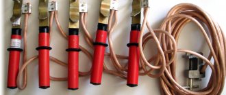
An effective additional PPE against induced voltage is the Ep-4(0) Tesla shunt kit. The operating principle of which is to shunt the current passing through the body of a person who has come under induced voltage. This happens due to the low electrical resistance of the kit (up to 0.1 Ohm), which is 4-5 orders of magnitude lower than the calculated electrical resistance of the human body (1 kOhm). Today, the Ep-4(0) Tesla kit has passed a set of laboratory tests conducted at the Research Institute MT RAMS, JSC "VNIIZhT", JSC "VNIIZhG", MPEI, Research Center for High-Voltage Equipment (SRC VVA). In addition, field tests were carried out on the lightning protection cable of a 750 kV overhead line. The test results showed that the magnitude of the induced voltage at which Tesla's Ep-4(0) provides guaranteed protection of a person from electrical injury is 10-12 kV. The amount of current flowing through the human body in this case ranges from several microamperes to tenths of a milliampere, which is below the human sensitivity threshold at a frequency of 50 Hz (1.5 mA). The Ep-4(0) Tesla set is designed to flow “bypassing” » human body current of up to 100 A for one to two minutes. At the same time, heating the kit does not lead to the destruction of its protective elements and does not cause discomfort to the user. All this indicates the ability of Tesla Ep-4(0) to protect personnel when exposed to voltage induced by capacitive and inductive means, when the current value can reach tens of amperes. The set, similar to ordinary workwear, includes special electrically conductive shoes, a work suit and gloves.
March 11th, 2016|
Induced Voltage Calculation
CALCULATION OF THE INDUCED VOLTAGE ON THE ANTENNA BLOCK OF THE DEVICE FOR PROTECTING THE CRANE FROM APPROACHING TO POWER LINES
Valentin Alekseevich POTAPOV, Ph.D. tech. Sciences, General Director, Vitaly Andreevich ROSCHIN, engineer of ZAO Engineering-Technical, Ivanteevka, Moscow region. Sergey Dmitrievich IVANOV, Ph.D. tech. Sciences, Associate Professor Moscow State Technical University. N.E. Bauman
An approximate calculation model for determining the voltage induced from power lines to the antenna unit (AB) of a device for protecting self-propelled jib cranes from dangerous proximity to power line wires is described. Assumptions in this model are introduced and justified for practical technical application in the development and design of antennas for security devices. Based on the results of full-scale field experiments with batteries of various shapes under different weather conditions and various urban conditions, a comparison was made of the calculated dependence of the induced voltage on the battery on the distance to the nearest power line wire and the same dependence obtained experimentally. The experimental results confirmed the applicability of the resulting calculation model for determining the induced voltage on the battery of safety devices.
Key words: safety device, antenna unit, approaching power line wires, crane protection, calculation of induced voltage. During construction, installation, loading, unloading and other work with jib self-propelled cranes, lifts (towers) near power lines (power lines), accidents occur due to electric shock to people even when the retractable and cargo parts of the lifting structure do not touch the power line wires, but are at an unacceptably close distance from it (0.5-1.2 m) or when a working person is at a certain distance from the power line and comes under step voltage. This places work near power lines among the most dangerous works performed with the help of lifting structures, and requires the presence of devices to protect against dangerous approach to power lines. Currently used devices monitor the electric field strength near an alternating current conductor, which is a power line wire. The sensitive element of the device is an antenna in the form of a closed metal circuit, placed on the head of the crane boom. The shape and size of the antennas that are part of the antenna units (AB) vary significantly, while affecting the level of EMF induced in the antenna (AB sensitivity). Therefore, each device must be calibrated on a power line simulator to establish response thresholds that ensure the crane stops at a safe distance from power line wires of various voltages [1]. But such calibration does not take into account a number of features of work in urban areas, in a limited space near power line supports and weather conditions - rain, snow, frost, which is confirmed by the experience of operating self-propelled jib cranes. To increase the efficiency of the antennas of protection devices, it is necessary to develop a theoretical model for calculating the induced voltage on the AB of the device, taking into account the features of the practical application of cranes. In general, the decision to stop the movement of the crane, which leads to the retractable parts of the crane (boom) and cargo parts entering the dangerous zone of the power line (crane stop), is made when the EMF induced in the AB reaches a certain threshold value. This value corresponds to the electric field strength at the boundary of the equipotential zone (Fig. 1), in which the location of the retractable and cargo parts of the jib crane is prohibited.
Source: Magazine Lifting and Transport Business 3-4.2018.
Measurement methods
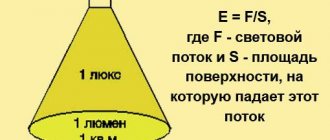
When introducing and routinely checking the condition of electrical installations, touch voltage is measured, let's learn about the measurement procedure. First, disconnect the neutral wire from the electrical panel. Then the resistance is measured with a milliohmmeter or a ground loop meter, type MRU-101. Then a circuit is assembled, where at a distance of at least 25 m from the ground electrode (number 2 in the figure), a pin is installed to a depth of 25-30 cm and an electrode similar to a human foot (indicated by number 3 in the figure). Voltage V1 is applied between the ground electrode and the pin. Voltmeter V2 – touch voltage. A 1000 Ohm resistor is installed in parallel to it (simulating the resistance of the human body) and a disconnector (when it is closed, a measurement is performed).
This is what an electrode that imitates a human foot looks like:
Where 1 is a cloth pad (wet), 2 is a conductive copper plate, 3 is a dielectric, 4 is a handle, 5 is a wire connected to the meter.
Another method is called the “voltmeter-ammeter method.” In the figure R2 is the body resistance:
The voltmeter measures the touch voltage, the ammeter measures the current through the ground electrode. As a voltage source, you can use a transformer with the following characteristics:
- Uout = 500 V;
- Pnom = 100 kVA;
Alternatives: autonomous generator, auxiliary transformer. Zero of the secondary winding - ground.
The video below clearly demonstrates a special device for measuring touch voltage:
Why is touch tension dangerous? You may get an electric shock, because the surface of the device contains the potential of the electrical supply network. Household appliances with a 220-volt power supply, such as an electric stove, are dangerous, and 380-volt industrial networks and harsh working conditions only aggravate the effect of touch voltage on a person. In order to avoid injury, in addition to preventive measures in the electrical network, you need to have a minimum set of personal protective equipment, for example, dielectric gloves and boots when working in electrical installations and comply with all protective measures prescribed in regulatory documents and company regulations.
It will be useful to read:
- How to use a megohmmeter
- Checking cable insulation resistance
- Protective means used in electrical installations up to 1000V
- How to make grounding in a private house
The procedure for determining the magnitude of the induced voltage
The scheme and procedure for measuring the magnitude of the induced voltage and its recalculation to the highest current of the influencing overhead line is approved by the technical manager based on the requirements set out in this section.
The induced voltage is determined by measuring the potential of the wire relative to the zero potential point.
The work of measuring the magnitude of the induced voltage is carried out according to the approval order for the overhead line brought out for repair and grounded in the switchgear and at the workplace. The measurement itself is performed after disconnecting the grounding installed at the workplace. In the “separate instructions” column of the permit, an entry must be made that allows grounding to be disconnected for the duration of measurements.
Measurements should be made on overhead lines in places where the highest values of induced voltages can be expected (Fig. 15):
at the beginning and end of the overhead line on the first supports installed outside the switchgear;
at points of change in the relative position of overhead lines;
at the points of separation of double-circuit overhead lines into single-circuit ones;
in places of transpositions on a disconnected or influencing overhead line.
Rice. 15. Locations of the expected highest values of induced voltage
The magnitude of the induced voltage is determined when the overhead line is disconnected and grounded in the switchgear.
On dead-end 6-20 kV overhead lines or overhead line taps, which, when taken out for repair, can be disconnected and grounded only on one side, the measurement is carried out according to grounding schemes, in which the overhead line is taken out for repair.
Measuring the induced voltage on a disconnected overhead line in the absence of grounding is carried out in exceptional cases to determine the electrostatic component of the induced voltage. Such measurements may be necessary to assess the possibility of safely performing work on an overhead line under construction or dismantling and in other cases when there is no electrical connection with the switchgear or it is difficult to perform reliable and high-quality grounding.
Repeated measurements should be performed when changing the routes of overhead lines, constructing or dismantling influencing overhead lines, reconstructing with a change in throughput and when determining the possibility of safely performing work under changed disconnection and grounding conditions (installation, dismantling of wires, changes in grounding schemes, etc.).
The connection of the measuring wires is carried out using a car lift or by lifting it onto an overhead line support. Voltage measurements are made on the ground without climbing to a height by two persons, one of whom changes the measurement schemes, the other takes the readings of the device. Personnel carrying out measurements must wear dielectric gloves and dielectric boots to protect against step voltage. It is unacceptable to touch measuring instruments, connecting conductors and grounding devices without using protective equipment designed for the magnitude of the induced voltage. Switching on, switching off and switching the measurement limits of devices is carried out after grounding the overhead line in the switchgear and at the workplace using protective equipment.
The induced voltage is measured relative to an electrode installed at a distance of at least 20 m from the grounding devices and buried at least 0.5 m into the ground. Installation of the electrode at a distance of at least 20 m is necessary to eliminate the influence of the potential of the support connected via a grounding cable to the grounding device The switchgear, which in turn is connected to the grounded wire of the overhead line. The measuring electrode can be placed in any direction relative to the overhead line. It is recommended to install the electrode perpendicular to the axis of the overhead line to eliminate the influence of the potential induced in the connecting conductor on the measurement circuit. On an overhead line without a lightning protection cable or with an insulated lightning protection cable, the induced voltage can be measured relative to the grounding device of the support.
To switch the measuring circuits, a three-phase three-position or two-position switch is used (Fig. 16). The switch insulation level is at least 1 kV. When measuring using circuits without grounding of overhead lines, the insulation level must be designed for the maximum value of the electrostatic component of the induced voltage, but not less than 10 kV. If a two-position switch is used, the measuring device is connected by alternately touching the switch contacts using an insulating rod. Using a two-position switch is less safe and does not allow phase sum measurements. The switching device is controlled in phases using an insulating rod of a voltage class corresponding to the voltage class of the overhead line wearing dielectric gloves. The requirement for the voltage class of the insulating rod is explained by the need to perform work in the absence of portable grounding at the workplace.
The measurement circuit uses connecting conductors with insulation rated for a voltage of at least 1 kV. When carrying out measurements without grounding of overhead lines, the insulation of connecting conductors installed without insulators must be designed for the value of the electrostatic component, but not less than 10 kV.
To measure the induced voltage on a grounded overhead line, an alternating current voltmeter with an upper measurement limit of up to 1 kV can be used. The use of devices with automatic switching of measurement limits can significantly increase work safety. The input resistance of a voltmeter used for measurements on a grounded overhead line must be at least 1 kOhm.
To measure the induced voltage without grounding the overhead line, kilovoltmeters are used. The upper measurement limit of the device is selected depending on the voltage class of the influencing overhead lines. The input resistance of the kilovoltmeter must be at least 1 MOhm.
Due to the relatively low resistance of the windings, the use of instrument transformers is unacceptable.
It is recommended to use special induced voltage meters. For example, induced voltage meter INN-15 manufactured by Elektropribor LLC, Krasnodar or similar. Measuring the induced voltage using special meters consisting of insulating rods is performed without the use of switching devices. Depending on the dimensions and design of the overhead line, these measurements can be performed with a rise to a height, or directly from the surface of the earth (Fig. 16).
Measuring instruments must be included in the register of measuring instruments and undergo metrological verification.
| Rice. 16. Examples of measuring induced voltage using a special meter |
When measuring induced voltage (including using special meters), it is important to ensure that safe distances are maintained to live parts under induced voltage, and also to avoid touching the conductive parts (ground wire) of the meter.
If there is a danger of touching the wire with body parts or the equipment used, it is necessary to use shunting (electrically conductive) sets of special clothing to protect against induced voltage.
When carrying out measurements, the date, time, place, phase, measurement scheme and load on each of the influencing overhead lines must be recorded for subsequent calculation of the maximum possible value.
It is recommended to carry out measurements with the highest possible loads of influencing overhead lines, which increases the accuracy of measurements. Measuring the voltage induced from the railway contact network must be performed at the moment the electric train passes. Measuring the induced voltage at minor loads (less than 20-25% of the nominal load) of the influencing overhead lines leads to erroneous results. In such cases, the measurement result is significantly influenced by the electrostatic component, which cannot be completely reduced due to the resistance of the wire and grounding devices, especially in the middle of the overhead line.
When the measured values are subsequently recalculated to the maximum current of the influencing overhead lines, the electrostatic component of the measured value, independent of the current of the influencing overhead lines, is also erroneously corrected, which leads to inflated values.
The measurement is performed in the following sequence:
The overhead line is disconnected and grounded, portable grounding is installed at the workplace (for safety purposes as part of the preparation of the workplace);
a switch and measuring instruments are installed on dielectric mats;
at a distance of at least 20 m from the support and other grounding devices, the measuring electrode is buried in the ground;
a circuit is assembled corresponding to Figure 17 (when measuring using circuits without disconnecting the grounding of the overhead line, a kilovoltmeter is not required);
grounded measuring wires are connected to the overhead line wires;
the portable grounding installed at the workplace is removed;
Using an insulating rod and a switch, the grounding of the measuring wires is disconnected and they are alternately connected to the measuring device. By searching through the options for grounding or ungrounding the wires and connecting the measuring device, a circuit with the maximum value of the induced voltage is selected.
| Rice. 17. Induced voltage measurement circuits using a three-position or two-position switch |
If it is necessary to determine the value of the induced voltage for various grounding schemes and without grounding of the overhead line, continue the measurement in the following order:
the grounding in the first switchgear is switched off and the induced voltage is measured according to the circuit without grounding in the first switchgear;
using an insulating rod, the voltmeter is disconnected from the measurement circuit to prevent it from being damaged by high voltage;
The grounding in the second switchgear is switched off and measurements are taken on an ungrounded overhead line using a kilovoltmeter. If the measured voltage does not exceed the permissible value for the voltmeter, it is connected to the circuit;
grounding is turned on in the first switchgear;
using an insulating rod, a previously disconnected voltmeter is connected and the induced voltage is measured according to a circuit without grounding in the second switchgear;
grounding is turned on in the second switchgear;
after carrying out the necessary measurements, the measuring wires are grounded using a switch, a protection device is installed at the workplace, the measuring wires are disconnected from the overhead line and the measurement circuit is disassembled.
On overhead lines with more than two switchgears, measurements are performed similarly.
At the end of the measurements, the value of the induced voltage is calculated at the highest operating current of the influencing line U max
, IN
where, U measured
— measured voltage, V;
I change
— load current of the influencing overhead line at the time of measurement, A;
I max
— the highest operating current of the influencing overhead line, A.
The maximum operating current is taken to be the maximum throughput value of the overhead line.
For dead-end overhead lines, the maximum value may be limited by the capacity of transformers or other equipment. In cases where the throughput significantly exceeds the maximum possible current, which leads to unreasonably inflated calculated values of the induced voltage, according to the decision of the technical manager, it is allowed to use the maximum possible current, taking into account all permissible operating modes of the network during periods of maximum load.
When passing a disconnected overhead line in the corridor of several influencing overhead lines:
where, I total max
– the sum of the maximum possible values of currents flowing through the influencing overhead lines:
I general measurement
– the sum of the maximum possible values of currents flowing through the influencing overhead lines at the time of measurement:
If the value of the maximum operating current of the influencing overhead line changes, it is necessary to recalculate the induced voltage using the values obtained during measurements.
Conversion of the electrostatic component measured on an ungrounded overhead line to the maximum current of the influencing overhead line is not required. There is a possibility of a significant increase in the electrostatic component relative to the measured value when disconnecting a section of the line that does not run parallel to the influencing overhead line. A dangerous value of the electrostatic component is possible during the installation and dismantling of the wire, when the mounted sections are grounded not in the switchgear, but along the overhead line.
Based on the measurements taken, recalculated to the maximum current, a list of overhead lines under induced voltage should be compiled. The list indicates the name of the disconnected overhead line, the name of the influencing overhead lines, the disconnection and grounding circuit under which the measurements were carried out and the value of the induced voltage for this circuit.
When carrying out repair work, it is necessary to take into account that the list of overhead lines under induced voltage indicates only those lines on which the induced voltage value is more than 25 V when grounded in the switchgear. In case of disconnection or poor-quality installation of grounding or if a wire breaks, a significant increase in the induced voltage on the overhead line is possible, incl. on lines not specified in the List.
On ungrounded or poorly grounded overhead lines, an electrostatic component of the induced voltage of more than 25 V may appear.
Inclusion of the value of the induced voltage in the list of overhead lines under induced voltage, obtained solely by calculation (without measuring the value of the induced voltage in the prescribed manner) is not permitted. It is allowed to carry out a preliminary (estimated) calculation of the value of the induced voltage for the following purposes:
preliminary assessment of the need for measurements;
analysis and selection of the safest overhead line grounding schemes;
determination of the danger of induced voltage on an overhead line under construction;
determination of the induced voltage in the event that in normal mode it is impossible to create a load on the influencing overhead line (the dividing point of the transit of two parallel lines in one switchgear, the load is possible only in emergency mode);
The calculation method is determined depending on the conditions and purposes of the calculation and is approved in the prescribed manner.
Induced voltage
The induced voltage on an idle current conductor is measured by applying short circuits provided for by the design. Measurements are taken mid-span between the short circuits. Using a portable voltmeter, alternately measure the voltage between different phases and between phases and ground.
| Symmetrical rigid conductors on support insulators. |
The induced voltage W can be significant, and to limit it when working on a disconnected circuit, short circuits are installed at the beginning and end of the conductor, and, if necessary, at its intermediate points so that the induced voltage does not exceed 250 V required by safety conditions.
The induced voltage U can be significant, and to limit it when working on a disconnected circuit, short circuits are installed. The number and location of short circuits is selected so that the U value does not exceed 250 V.
The induced voltage V can be significant and to limit it when working on a disconnected circuit, short circuits are installed at the beginning and end of the conductor, if necessary, and at intermediate points so that the induced voltage does not exceed 250 V required by safety conditions.
If the induced voltage is high, the two ends must be grounded. In this case, induced currents arise in the screen, which leads to additional heating of the cable. However, losses in the screen are still much less than losses in the central conductor, and the maximum additional heating is in the range from 1 to 3 C.
This induced voltage is amplified and recorded. It can be assumed that the rotating field H causes the coherence of spin precession, resulting in a macroscopic magnetic moment that precesses with frequency VQ. In another version of the circuit, the exciting and receiving coils are combined and the process of reorientation of the nuclei is detected as absorption of the energy of the RF field.
| AC voltage U. |
This induced AC voltage is subjected to half-wave rectification in the bridge converter of the cathodic protection station, increases the protective current and thereby causes a decrease in the pipe-soil potential. Since the operating current in a high-voltage overhead line or on a section of an electrified railway changes over time, a synchronous change occurs in both the induced voltage and, with it, the rectified alternating current, as a result of which the pipe-ground potential continuously fluctuates. Optimal setup of a cathodic protection station under such conditions becomes difficult or even impossible. Converters that are resistant to high voltage are also beneficial in this case, because their chokes sharply reduce the induced alternating voltage. As a result, the pipe-soil potential is stabilized.
The polarity of the induced voltage, depending on the relative position and direction of winding of the coils, may coincide (be consistent) or not coincide (be counter) with the accepted positive polarity of the voltage of the second coil.
The magnitude of induced voltages in semiconductor relays is significantly less than in electromechanical relays. The dead zones of these protections also have smaller values, and as a result, there may still be a loss of directionality of the relay action in the case under consideration.
The phase of the induced voltage is shifted relative to the current by 90 and can thus differ significantly from the phase of the electrostatically induced voltage. The action of higher harmonics of the transmission line current is proportional to frequency, as can be seen from relation (31.4), and can lead to disruption of the operation of telephone lines, especially since telephone lines are more sensitive to them than to the fundamental harmonic.
The chapter is devoted to the dangers of induced voltages and protection against them; here we will limit ourselves to only examples. The danger of such voltages is especially great if the vehicle is carrying fire and explosive cargo.
To reduce induced voltages on pipelines, grounding devices are mainly used. Protective groundings are installed in places on pipelines where pipeline voltages induced by an electrified railway exceed permissible limits.
In the zone of induced voltage, when working on wires (cables) performed from a telescopic tower or other mechanism for lifting people that does not have an insulating link, their working platforms are connected by means of a portable grounding to the wire (cable), and the tower or mechanism itself is grounded. The wire (cable) must be grounded at the nearest support.
Induced voltage and protective measures
The Safety Rules (STR) for the operation of electrical installations define safety measures during work on overhead power lines (OHLs), on which additional voltage is induced from neighboring operating lines. Separately, safety measures are highlighted when working on such overhead lines, when grounding them in accordance with the general requirements of the rules does not allow reducing the level of potential induced on disconnected wires below 25 V.
However, cases of injury to service personnel by electric current of induced voltage continue to occur, which are the result of a misunderstanding of the nature of the occurrence and the mechanism of manifestation of this voltage. The peculiarity of its manifestation is that there remains a danger of electric shock when touching even a wire that is grounded according to the rules.
It is known that on any overhead line running in parallel with other overhead lines, a third-party potential is continuously induced due to the mutual influence of the electromagnetic fields of these lines on each other. The potential value depends on the operating voltage, load currents, the distance between the phase wires of the lines and the length of the section of their parallel location.
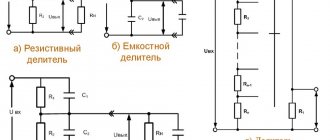
The potential induced on each of these lines (induced voltage) can be conventionally represented as the sum of two components: electrostatic and electromagnetic .
The electrostatic component of the induced voltage on the wires of a disconnected overhead line is caused by the influence on them of the electric field of the adjacent (influencing) line remaining in operation and, while maintaining the design parameters of the parallel section defined by the PUE, depends only on the voltage level of the influencing line. The value of this component is the same along the entire length of the disconnected overhead line (Fig. 1) and is determined by the formula:
Uе = k Uр.в.
where k is the capacitive coupling coefficient of the lines;
Uр.в. – operating voltage of the influencing line.
Rice. 1. Distribution diagram of the electrostatic component of the induced voltage.
The electrostatic component of the induced voltage is reduced to a safe level along the entire length of the line when it is grounded at any, at least one point. Consequently, the impact of this component is completely eliminated when the disconnected overhead line is grounded at the ends (at substations) and at the work site in accordance with the safety regulations.
The electromagnetic component of the induced voltage manifests itself quite differently, the occurrence of which is due to the total influence of magnetic fields created by the currents of the phase wires of the influencing line.
The EMF induced on a disconnected line is determined by the expression:
E=MLI
where M is the inductive coupling coefficient of the phase wires of the line at a frequency of 50 Hz;
L – length of the parallel line section;
I – load current of the influencing line.
The inductive coupling coefficient for each specific “corridor” of lines remains virtually unchanged. In this regard, the value of the induced EMF is determined only by the length of the parallel section of the lines and the load current of the influencing line and does not depend on the level of operating voltages of each of the overhead lines.
In this case, the potential (voltage relative to the ground) of any point, for example x, is determined by the expression:
U=- E/L *x + E/2
where E is the EMF induced on the wire;
x – distance from the beginning of the line to point x.
It follows that at the beginning of the line (at x=0) the electromagnetic component of the induced voltage Uн=+E/2, at the end of the line Uк=-E/2 (at x= L) in the middle of the line Uср=0 (at x=L /2).
A feature of the manifestation of the electromagnetic component of the induced voltage is the invariance of its value, regardless of whether the wire is isolated from the ground or grounded in one or even several places.
When the number of grounding points on an overhead line changes, only the position of the zero potential point on it changes. The specificity of this manifestation of induced voltage is what determines the requirements of the PTB.
Rice. 2. Diagram of distribution of the electromagnetic component of the induced voltage on a disconnected overhead line depending on the location of installation of protective grounding on it.
In Fig. Figure 2 shows typical examples of the distribution of the electromagnetic component of the induced voltage (potential) on a disconnected overhead line depending on the location of the installation of protective grounding. As can be seen from the diagrams, with a single grounding of the overhead line, the point of zero potential coincides with the grounding point.
Taking into account the above, a graphical justification of the danger of organizing two or more workplaces simultaneously on an overhead line located in the zone of inducing the electromagnetic component of voltage is presented. For example, a team works at point C, the line, according to the rules, is grounded only at this one point, where the voltage is zero (Fig. 3a).
If now, to prepare the second workplace, we install protective grounding at another point D, then the zero potential will move to the area between these two groundings (Fig. 3b). In this case, the voltage at the grounding points (points C and D) may exceed the permissible level, and people working there will be at risk of electric shock.
A similar effect manifests itself when working on a linear disconnector that is under the induced voltage of an overhead line. Grounding the disconnector on the line side in this case guarantees electrical safety only on the condition that this line is not grounded anywhere else (see Fig. 2b, d).
If you install additional grounding in some other area, for example, turn on the grounding blades at the substation from the other end of the line, then the level of induced voltage at the line disconnector at the work site will “jump” to the maximum (see Fig. 2d).
Rice. 3. Examples of the distribution of the electromagnetic component of voltage on a disconnected overhead line when a repair crew is working in various conditions.
Manifestations of induced voltage force operating personnel to sharply reduce the scope of work on overhead lines (to one team) located in the zone of increased action of this voltage. Dividing the line into separate electrically unconnected sections by cutting the loops also causes additional time spent on alternate cutting and their subsequent restoration. However, the need to ensure the safety of line personnel obliges us to take these facts into account.
At the same time, one of the alternative measures that removes almost all restrictions on expanding the scope of work in all cases (while maintaining the safety of line personnel) is to perform work under voltage.
When preparing a workplace on an overhead line, special attention should be paid to the reliability of the protective grounding contacts with the phase wires and the ground electrode. We must not forget that in the event of an accidental loss of contact (disconnection of the line), the point of zero potential at the same instant can change its location, and the voltage in the workplace exceed the permissible value Uс (Fig. 4). Therefore, to guarantee safety at the work site, it is advisable to install two ground connections in parallel.
Rice. 4. Diagram of the distribution of the electromagnetic component of the induced voltage when the line is grounded at point C and when it is ungrounded
So, the electromagnetic component of the induced voltage reaches its greatest value at the boundaries of the area of mutual influence of lines (in the general case, at disconnected linear disconnectors). It is at these points, directly at the descent of the grounding bus of the linear disconnector or at the first support from the substation, that measurements should be made with the grounding blades turned on at both ends of the line.
The voltage class of the voltmeters used for this must be selected according to the expected level of induced voltage. As a first approximation, you can use a voltmeter with a measurement limit of up to 0.5í1.0 kV.
Recalculation of measurement results to the conditions of maximum loads of the influencing line can be carried out using the formula obtained from the relationship:
where Umeas – measured induced voltage;
Imeas – load current of the influencing overhead line at the time of measurement;
Imax – maximum permissible load current of the influencing line.
It should be noted that the switched-on grounding blades, disconnector frame, connecting wires and voltmeter may be under dangerous voltage during measurements. In order to ensure the safety of the personnel performing measurements, the measurement circuit should be connected to the phase wires of the line only after assembling the measurement circuit. If it is necessary to switch the scale limits or replace the voltmeter, you must first disconnect the measurement circuit from the overhead line wire.
Personnel must use dielectric boots and gloves. The wires used for measurements must have insulation rated for a voltage of 1 kV.
Calculation of touch voltage
In networks with an isolated neutral, the touch voltage is calculated using the formula:
Uprik=Fland-Fcorps
The ground potential decreases with distance from the grounding point, this is illustrated in the picture above. In the case where there is only one ground electrode, the most dangerous contact will be with the body of the device that is located farthest from the ground electrode. Therefore, the grounding circuit must unite the entire area of the room and ensure uniform potential equalization.
The complete formula, taking into account all resistances (touching, spreading zones), is as follows:
U=Фзa1a2,
Where a1 is the contact U coefficient, it is influenced by the shape of the potential drop curve, a2 is the contact coefficient, takes into account the resistance to spreading over the area on which the person stands, shoes, and phase isolation from the ground.
In networks with a solidly grounded neutral, when a person is exposed to a voltage lower than linear (with linear 380V, phase is 220V), the current flowing through the human body is limited by the resistance of shoes, floor (ground) and body.
Main threats
The lack of response of the protection equipment to this type of voltage makes it much more insidious than an ordinary worker. If a person enters such an area, he will be under dangerous influence until he can be evacuated from this place. The operating voltage causes a short circuit, as a result of which the automatic protection is activated.
There is another, frequently encountered aspect of the short circuit problem - a short circuit. If it occurs in a working line, it immediately triggers an overhead line that is under repair and de-energized. Personnel working in this area are exposed to a real risk of injury from repeated excess current. Unpredictable consequences from burns to death are almost inevitable. Only the most scrupulous compliance with regulatory standards, instructions and safety rules remains the law for work on disconnected lines.
All of the above raises a natural question - how to neutralize the consequences of a person falling under this type of stress? The first and mandatory step is to stop the current flowing through the body.
First of all, you will need to connect the dangerous section of the installation to the “ground” using a grounding method. The rules for safely carrying out the work process in places with an increased likelihood of such interference are discussed in the following video.
https://youtube.com/watch?v=ynQkwQWJq6c
What is the danger of the phenomenon?
The induced voltage can be considered more dangerous and insidious than the working voltage due to the fact that protective equipment will not respond to it. If repair personnel fall under it, then the employee will be under the influence until freed from its influence. If a person is exposed to operating voltage, then the protection will be triggered and an automatic shutdown will occur.
You also need to be aware of short circuits. If a short circuit occurs on the working line, it will occur on a disconnected overhead line and the current will exceed multiple times. Naturally, this may affect the personnel who will be busy repairing the disconnected overhead line. The consequences in most cases can be quite dire. It can start from burns and lead to deaths. That is why, when carrying out various works on disconnected overhead lines, it is necessary to follow all safety rules. If you are interested, you can read about electrolytic grounding.
What to do if a person comes under induced voltage? This question is currently of interest to many and should be dealt with in more detail. First you will need to prevent current from flowing through the person's body. To do this, you may need to connect the hazardous part of the electrical installation to ground. Below you can see a video that will tell you all the safety rules when working in an area of increased interference.
Induced voltage
» Electrical installation » Grounding » Induced voltage
The occurrence of interference on overhead power lines and in electrical installations that are connected to them can pose a danger. That is why you need to understand in detail what induced voltage is.
Also, a similar phenomenon can occur in domestic conditions on a 220 Volt network. That is why you definitely need to understand the nature of the occurrence and measures to protect against induced voltage.
Causes
In most cases, the induced voltage will occur on an overhead power line that has been removed for repairs and is de-energized.
It can also occur if an electromagnetic field is located near a high-voltage line.
Thus, the overhead line, which comes parallel to the disconnected line, introduces third-party potential, which in the future will pose a danger to the repair team.
At the moment, the value of the induced voltage in the wire may vary depending on the length of the section where the overhead lines will run in parallel. Also, the change in value will be affected by the distance of the phase wires and meteorological conditions. The potential that will be induced on the overhead line can combine two types of influence - electromagnetic and electrostatic components:
- The electromagnetic part will appear under the influence of a magnetic field, which arises from the flow of current through a nearby overhead line. A distinctive feature is that when grounded, even in several places on the line, it will not change its value. The only thing that can be changed by grounding is that this is the location of the zero potential point.
- The electrostatic part, unlike the electromagnetic part, is eliminated by grounding the line at its ends and carrying out work together. To reduce the magnitude of the induced voltage, it is necessary to install at least one point on the overhead line.
Find out also about portable grounding and its operating principle.
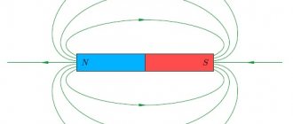
Now it is necessary to understand in more detail about the induced voltage and the nature of its occurrence. To understand how it appears, study the photo below:
If there is a conductor, which is indicated in the picture as A-A. If alternating current flows through it, then an electromagnetic field will be created, the intensity of which will decrease with distance from the conductor.
The pulsations of the electromagnetic field can also change with changes in the direction and magnitude of the current. If anyone else enters the field, an induced voltage can be induced.
At the moment, many do not know what value will be dangerous for personnel? If there is voltage present on the disconnected overhead line and its value does not exceed 25 V. All repair measures will be carried out using conventional protective equipment.
If the value is exceeded, then it will be necessary to use special protective equipment and carry out various technical measures. At the moment, such safety measures can be disconnection at the beginning and end of the line, cutting the wire.
Tip-off in the apartment
At the moment, many experts claim that induced voltage can also occur in an apartment and in a house on a 220 Volt network.
“Pickup” in most cases will appear in the cable when applied next to the wire through which the current will flow. For example, when the diode light bulbs have a barely noticeable glow when the switch is on.
In most cases, a similar situation can occur due to the fact that a conductor with a phase conductor will be laid next to the wire.
As a result of exposure to the electromagnetic field, slight interference will occur. Its size will be quite enough to illuminate small LEDs. Sometimes interference can also occur in the socket. It occurs when the neutral wire breaks. To get a more detailed example of the effect of interference, you need to watch the video.
Now you know exactly what induced voltage is and how it is dangerous for human life. We hope this information was useful and interesting.
Induced Voltage Hazard
Anyone who works with electricity should remember that, unlike an ordinary worker, induced voltage is a very dangerous phenomenon from which traditional protective devices and equipment cannot protect. When one of the maintenance personnel falls under its influence, he will remain in this state until he is freed from the negative influence with outside help. In the same situation, at operating voltage, the protection is triggered and the circuit is automatically turned off.
A short circuit also has a negative effect. When a short circuit occurs on a working line, multiple excess current also affects the disconnected overhead line. Working personnel may suffer burns, and in some cases death cannot be ruled out. Therefore, even if the network is completely disconnected, it is still necessary to comply with all electrical safety rules on the line.
If a person nevertheless falls under the influence of the induced voltage, the flow of current through the body should be stopped as quickly as possible. One of the rescue technical measures is to connect the dangerous part of the electrical installation to the ground. The simplest thing that can be done in this situation is to remove the wire using any insulated object.
Ways to reduce the danger
Let's figure out how to protect yourself from touch tension. To reduce the risk of potential occurring on the housings of electrical appliances, it is necessary, firstly, to ensure reliable grounding. Moreover, the resistance of the transition contact of the ground electrode (metal connection) should not exceed 0.01 Ohm. The connection point must be securely bolted or welded and must be checked regularly.
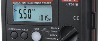
Secondly, before turning on devices after a long period of inactivity and generally old ones (more than 10 years), you need to check the quality of the insulation of wires and cables; for this, use a megohmmeter. As a guide, the insulation resistance should be 1 MOhm (megaohm) per 1 kV. For an electrical network of 220-380 Volts, 0.5 MOhm is sufficient.
To reduce the possibility of electric shock, it is necessary to install an RCD or a circuit breaker. Their purpose is to protect people from electric shock. But here we need a TN-CS or TN-S grounding system, that is, the network must have separate PE and N wires, but not a combined neutral wire. It is necessary to comply with the protection requirements, otherwise the RCD will not perform its tasks correctly.
Determination of induced voltage
Having decided on statics, we can formally calculate the value of the EMF for each section of work. However, if there is normal grounding (along the edges and at the point of work), the danger is practically zero.
But with electromagnetic guidance you will have to work hard. If the area is relatively small, you can simply measure the potential difference at the ends of the passive conductor.
Of course, all measurements are carried out in the presence of normal current load on the influencing line. That is, under conditions when the induced voltage reaches its maximum value.
The measurement technique is as follows:
The general principle comes down to measuring the potential difference between the real “ground” and the supposed point of zero potential, that is, the temporary grounding of a de-energized conductor. The distance from the “ground” to the point of zero potential must be at least 15–20 m.
A flexible copper wire is connected to the measuring probe, the cross-section of which allows work to be carried out with this voltage. The second end of the conductor is connected to the measuring device. The second terminal of the device is connected to real ground.
The measurement is carried out by at least two workers. One is located at the device, and the second throws the probe onto the conductor being measured.
Measuring points are determined before the start of the operation, the value is methodically recorded by the first operator on the graph.
When moving to another area, the measurement circuit is disassembled and the temporary grounding is dismantled. The equipment is transferred to a new location, where it is installed again, taking into account the measurement area.
Decisions are made when the voltage remains above 42 volts on the conductors and steel harness (braces, bands, etc.).
Safety precautions when determining induced voltage
- The personnel must have an electrical safety group of at least III, and the work manager must have at least IV.
- Experience in installation and maintenance of lightning protection and power lines is desirable.
- A security perimeter is organized around the measurement area.
- For safety reasons, the neutral cable in the group being measured is considered to be live.
- The beginning and end of work are documented.
- It is prohibited to take measurements in conditions of precipitation, heavy fog, poor visibility, or strong wind.
- If damage to a support, insulator or high-voltage cable is detected in the measured area, work is stopped until the problem is eliminated.
This is interesting: Zero bus
Induced voltage and its features
The relevance of the article “Analysis of the main changes in POTEE for work under induced voltage” (authors: I.V. Korolev, O.S. Shcherbacheva, A.M. Borovkova, D.A. Burdyukov) is undeniable.
In particular, the “method” of working without grounding overhead lines at the ends in the switchgear with grounding only at the workplace has been actively discussed in periodicals for more than 35 years. In 1984, the rules introduced a requirement to divide overhead lines into those that were and were not under induced voltage according to its value of 42 V (later 25 V), a method of working without grounding overhead lines at the ends in the switchgear with grounding only at the workplace appeared, and a requirement appeared to compile lists of overhead lines under induced voltage. These innovations were presented as a solution to labor safety problems when working on overhead lines under induced voltage. But at the same time, all previously existing requirements in the rules for protection from induced voltage when working on overhead lines and outdoor switchgear equipment were retained and are still included in the rules in their original form. The above-mentioned innovations were edited five times from 1984 to 2013. At the insistence of operating organizations, the ORGRES company only in 1993 released a method for measuring the amount of “induced voltage” on overhead lines. And it became obvious to specialists in the operation of overhead lines and substations that the theory on which the “innovations” were based was erroneous: the measurement of the induced voltage was not carried out between an ungrounded wire (lightning cable) at the measurement site and grounded conductive parts, but the voltage drop was measured on a section of land 15 - 20 in length m from the place of grounding of wires (lightning cables). Such a substitution of the definition of the term and the attached graphs of the distribution of the voltage drop on the ground electrode along the overhead line unacceptably distorted the provisions of electrical engineering. There were inconsistencies with the terms and requirements of PUE-5(6), and now PUE-7 section 1.7. "Grounding and protective measures for electrical safety." In 2009, the methodology of the ORGRES company migrated to the methodology of JSC FGC UES. The magnitude of the voltage drop across the support ground electrode, of course, depends on many factors. But there is simply no connection between the magnitude of the voltage drop on the ground electrode and the magnitude of the induced voltage on this support between the ungrounded wire (lightning cable) and grounded conductive parts, between the wires of the split phase, as well as the magnitude of the voltage between the wires (lightning cables) when cutting (connecting). The magnitude of the induced voltage reaches 1 - 50 kV on overhead lines of different voltage classes (this is known to electric linemen), and not 25-50 V (calculated according to the methods of the ORGRES company or JSC FGC UES). The magnitude of the voltage drop across the ground electrode, even 25 - 50 V, is reduced to zero and does not affect the safety of work when performing POTEEU clause 38.53. “Steel traction ropes used when installing wires on overhead lines under induced voltage must first be secured to the traction mechanism and grounded to the same ground electrode as the wire to equalize the potentials. Only after this is it allowed to attach the rope to the wire. The wire and the traction rope can be disconnected only after their potentials have been equalized, that is, after each of them has been connected to a common ground electrode. (clause as amended by Order of the Ministry of Labor of Russia dated February 19, 2016 N 74n).” For lightning cables, it does not matter whether the overhead line is grounded or ungrounded in the switchgear. Consequently, it would never occur to an electrician to measure and divide overhead lines into those that are and are not under induced voltage on the basis of this measurement when drawing up a PPR. Changes in POTEEU specified in Order of the Ministry of Labor of Russia dated 02/19/2016 No. 74n “On introducing changes to POTEEU, approved by Order of the Ministry of Labor of Russia dated 07/24/2013 No. 328n” bring clarity to the definition of places on overhead lines where there is induced voltage. The indication that the induced voltage is present on ungrounded wires (ground wires) of the overhead line grounded at the ends at the proposed work site is fundamental. It is fundamental to indicate the use of a method for equalizing the potentials of disconnected current-carrying and conductive parts in the workplace, which complies with the requirements of the PUE. All the requirements for grounding on overhead lines at the ends in the switchgear and at workplaces, as indicated at the beginning, preserved from the edition of the Rules until 1984, become clear. These surviving requirements fully ensure labor protection when working under induced voltage. A situation arose when these same requirements allowed the personnel not to pay attention to the presence of text related to the division of overhead lines into those under induced voltage and those not under induced voltage, and the authors of the “method” did not have an idea of how labor protection was ensured. Inexperienced personnel attempting to apply the “method” inevitably increased injury rates. That is, the overhead line, in accordance with the requirements of POTEEU, which actually provides protection from induced voltage, must be grounded at the ends in the switchgear, when cutting (connecting) wires (lighting cables), connecting to the wires (lighting cables) of aerial platform cradles, rigging and tools. It is important to note that the procedure for installing and maintaining the reliability of grounding must be observed when preparing the workplace, during work, and upon completion of work both on overhead lines and on substation equipment. All these grounds (grounding conductors) perform the function of equalizing the potentials of current-carrying and non-conducting parts (including the ground in the work area), which is a sufficient requirement according to PUE-7 section 1.7. "Grounding and protective measures for electrical safety." Consequently, the so-called “method of working without grounding overhead lines at the ends in the switchgear with grounding only at the workplace” cannot be used without taking measures to equalize the potentials of wires (lighting cables), rigging, tools and ground. If it is possible to exclude the approaches of the “method of working without grounding the overhead lines at the ends in the switchgear with grounding only at the workplace,” then the POTEEU will acquire an electrically understandable justification for safety measures, and there will also be compliance with the safety measures specified in different sections of the POTEEU for work on the overhead lines and RU equipment . This will eliminate the rules from mentioning the value “25 V”, the need to measure the magnitude of induced voltage on overhead lines, divide and compile lists of overhead lines into those under induced voltage and those not under induced voltage, eliminate the production of “protective equipment against induced voltage”, correctly apply the method of working under voltage, and will also bring the rules in line with the PUE, which states that it is always necessary to protect personnel and the population. In the article under discussion, it was no coincidence that attention was drawn to the fact that the value of 25 V does not correspond to the minimum permissible value; that the recalculation of the measured value of the voltage drop across the ground electrode is not determined; that according to Order No. 328 it was allowed to determine overhead lines for inclusion in the list by calculation, and according to Order No. 74 only by measurements; that the design of the influencing network is constantly changing; that there are no full-fledged TC and PPR; that there are no methodological manuals and programs for theoretical and practical training of personnel; that they cannot release a method for measuring induced voltage (it is known that operating organizations refused to measure according to the methods and design of a new one, proposing to measure voltage drop on grounding conductors that appears unknown from what currents. Conclusions 1. Order of the Ministry of Labor of Russia dated February 19, 2016 No. 74n “On introducing amendments to POTEEU, approved by order of the Ministry of Labor of Russia dated July 24, 2013 No. 328n "is a fundamental breakthrough in labor protection when working on overhead lines and on substation equipment under induced voltage. 2. Organizations responsible for the quality of safety measures requirements need to bring the Rules into compliance with the basics of electrical engineering and the requirements of the PUE, recognize the unity of the laws of physics for overhead lines and substation, and also exclude the text related to the “method of grounding overhead lines at one point.” 3. Methods for measuring “induced voltages on overhead lines” from ORGRES (1993) and JSC FGC UES (2009) officially cancelled. Reply
Purpose
MVP (minimum voltage protection) is used in conjunction with protections that monitor the network. Operated in conjunction with an automatic transfer switch (ATS) device. The ZMN performs a shutdown or sends an appropriate signal to the user (system) when an emergency occurs in the consumer network, as a result of:
- Short circuit when significant power loss occurs. Large currents arise and the voltage drops sharply.
- Network congestion. (The power supply is insufficient or one of them has failed).
This action ensures the safety of important mechanisms during self-starting, when inrush currents cause a decrease in voltage. Automation turns off the operation of less important mechanisms.
Causes
A detailed study of the noted processes allows not only to define the induced voltage. You need to figure out how to get rid of potential dangers. Careful testing using specific examples will help create a strong defense.
On an overhead line (VL)
In such objects the processes under consideration manifest themselves with particular force. The high-voltage characteristics of the circuits have a significant negative impact. It should also be noted the relative proximity of the wires. Increasing the distance significantly complicates the design, which is accompanied by additional investment costs. The potential induced in a de-energized section of the line can rise to an extremely dangerous level.
Large electrical interference can create significant problems. Its value depends on the following parameters:
- voltage in the working part of the networks;
- current strength (connected load);
- relative position of conductors;
- level of humidity, pollution, and other factors that change the conductivity of the intermediate medium.
The total potential can be divided into two parts. Static – creates an electric field from the nearest wire. The induced voltage is formed throughout the entire section of the adjacent conductor; it is not necessarily part of the line. Similar phenomena can be recorded by measuring instruments in support masts, fasteners and other elements with conductive properties. An effective safety measure in this case is to ground certain parts of the structure.
The other component is formed by an alternating electromagnetic field near the phase wires. The main trouble is the lack of simple solutions in the field of electrical safety. In this situation, even effective grounding will not help. High-quality insulation that is not capable of blocking the penetration of electromagnetic waves is useless. The potential at a certain point depends on the field strength parameters and the distance to the signal source.
In electrical installations
Similar negative phenomena are observed in local networks. Maximum voltage levels are in disconnected line switches. Induced currents can form in a transformer, housing, or mechanical drive of an electrical installation. As in the examples discussed above, the greatest difficulties arise when searching for effective methods of dealing with the variable component.
For your information. Sources of danger can be a metal ceiling, floor, or other functional or decorative element of a building structure.
In the apartment
Reducing the voltage to 220 V reduces but does not completely eliminate possible troubles. The increased energy consumption of a modern apartment should be taken into account. Cooktops, ovens and air conditioners operate using high currents. The total power of the new equipment is tens of kW. Additional problems are created by the frequency of switching on and the reactive nature of the loads.
For your information. A good example is LEDs operating in a disconnected circuit, located next to the wires of the 220V power supply.
Using this scheme, you can make a device for removing interference from an LED
In electrical wiring
The next typical case is a break (disconnection) of the neutral wire. If you use a multimeter according to standard measurement methods, it is easy to detect the presence of two phases in the outlet. It is clear that this is impossible in a standard 220 V household network. The second voltage will induce electromagnetic radiation in the disconnected conductor. To restore the normal state of the system, it is enough to restore the damaged current circuit.
ZMN scheme
The protection system is usually implemented using electromagnetic or electronic voltage relays. This is a kind of reacting organ in the chain.
Relay contacts are connected in series to prevent failure when fuses in electrical circuits blow. The relay contacts are supplied with phase through an auxiliary contact from a sectional transformer or electrical network.
Additionally, the ZMN includes relays:
- Time to ensure consistency of operation in an electrical circuit.
- Intermediate, switching control signals.
- The index finger, which signals when the protection is triggered.
- Minimum voltage.
Also, the industrial protection system includes line contactors or electromagnetic starters.
When the indicators drop to 50 percent of the nominal value, the contactor turns off, opens the contact that bypasses the start button, and prevents self-starting of the engine or machine.
With such a system, the mechanisms start after pressing a button that closes the circuit.
ZMN can operate autonomously or in conjunction with current protections.
AVR system
In the event of a prolonged absence of electrical power, a shutdown also occurs on the main electric motors. This is necessary to start the ATS (automatic transfer switch), and the production technology also requires it.
When the power supply to the sectional input is interrupted, the automatic system turns on the reserve, and the sectional switch is turned on, providing power supply from the backup source.
The minimum operating time of the ATS depends on the delay in the system that controls the input of the operating voltage, the operating time of the intermediate relays, the time intervals for turning off and turning on the switches of the working and backup input.
Why does induced voltage occur?
In many cases, induced voltage appears on de-energized overhead power lines that are taken out of service for repairs. The main condition for its occurrence is considered to be an electromagnetic field located near a high-voltage line. This overhead line, running parallel to the disconnected line, induces external potential. This will be the simplest answer to the question of what induced voltage is.
The value of this parameter is constantly changing, depending on the influence of certain factors, such as the length of the section, the distance to the phase wires, and certain meteorological conditions.
- The electromagnetic component is formed under the influence of a magnetic field. The field itself, in turn, arises under the influence of current flowing through a high-voltage line located nearby. Its value will remain unchanged even if there is grounding installed in several places. Under the influence of grounding, only the place where the point with zero potential is located can change.
- The electrostatic part, on the contrary, can be neutralized using a grounding system, which is installed at the ends of the line and at the work sites. The magnitude of the induced voltage is reduced if grounding is performed at least at one point of the high-voltage line.
Theoretically, the occurrence of induced voltage occurs in the following order. If alternating current flows through a conductor, an electromagnetic field will be created around it. The field intensity will decrease with gradual distance from the conductor.
In addition, a change in ripple is observed in the electromagnetic field when the direction and magnitude of the current also changes. If any other conductor comes within the range of the field, an induced voltage will be induced in it. The voltage value is determined using connected measuring instruments. In this way, the degree of danger for operating personnel is determined.
For example, if a disconnected high-voltage line is under voltage not exceeding 25 volts, repair work can be carried out using conventional protective equipment. When this value is exceeded, special technical measures and the use of additional protective equipment will be required.
Cases of injury to a person by an induced charge
The equipment of an energized electrical installation is surrounded by an electromagnetic field (EF), which, according to the laws of induction, affects all metal objects located in the affected areas.
The magnitude of the induced potential depends primarily on the voltage, the power of the electrical installation and the dimensions of the objects in which the charge is induced. Particularly dangerous is the location of objects under high-voltage equipment and overhead power lines.
Under the influence of an EF source, charges are distributed on the surfaces of conductive objects in such a way that their total field is equalized to zero in the conductor. At the same time, the relaxation period in metals is very short - about 10-18 seconds, which ensures almost instantaneous reproduction of changes in the external field.
When the external EF source is turned off, the induced charges disappear.
For linear metal objects located in the zone of a high-frequency electromagnetic field, an electromotive force is formed according to the laws of electromagnetic induction. Its value can reach 1 kV. The size of the capacitive parasitic connections influences the magnitude of the induced potential.
Typical examples of the appearance of an induced potential
. The movement and operation of motor vehicles, various mechanisms in the overhead line zone, and equipment of high-voltage substations is associated with the occurrence of an induced charge in them.
Carrying or simply placing long metal objects: rods, fittings, corners, ladders and other materials under high-voltage wires creates an induced charge on them.
The spare conductors of electrical cables laid in areas of electromagnetic field are induced by a potential that can reach a significant value. Even for the main 0.4 kV network, the voltage of the reserve cores in some cases can reach 150 volts relative to ground.
Protective measures
. Only prepared and trained personnel are allowed to work in areas influenced by electromagnetic fields, who must have a good understanding of the existing danger.
To remove the induced charge from metal products, grounding is used. Wheeled vehicles in the ES coverage area should only move with a metal chain that creates contact with the ground.
When working on site, all machines and mechanisms are connected to a ground loop or grounded with portable ground electrodes.
The movement of long objects, ladders, etc. must be planned and carried out with portable grounding after organizational measures have been taken.
Work with cables must be carried out only with the use of proven protective tools in accordance with work orders or orders.
Possible consequences of the action of an induced charge
. Violations of the rules for handling an induced charge can lead to the most severe consequences: secondary injuries, burns from spark or arc discharges, fires from the ignition of fuel and flammable liquids.