Nuances
Metal bond measurements are carried out immediately after installation, right before start-up and operation, and then, at intervals of 3 years, during routine testing and maintenance. Along with the check, as well as when the season changes, when flooding and excessive humidity are possible, the insulation resistance of cables and electrical machines is checked.
It will not be possible to check the quality of the contact and measure its contact resistance using a simple household multimeter, such as DT830 and the like. In the region of low resistances, they either do not measure at all (up to tenths, but not hundredths of an ohm), and the resistance between the probes alone reaches 1 ohm, and sometimes exceeds. There is no need to talk about accuracy here.
Sometimes, to measure the quality of a contact, instruments are not needed, since its destruction is obvious. In extreme cases, it comes to the point that you can measure its temperature with your hand; if it gets hot, then it needs preventive maintenance and subsequent measurements and testing with a milliohmmeter.
Finally, we recommend watching a video that clearly shows how to check the presence of metal connections with the device:
Checking metal communications is very important for the life safety of enterprise employees and house residents. Due to poor grounding in sockets or its complete absence, there is a possibility of potential appearing on the device body. And when a person touches it, either electrical injury or something irreparable will occur. We hope the information provided was useful and interesting for you!
We also recommend reading:
- How to check the functionality of the automatic machine
- Ground resistance measurement
- Why do you need a zero bus?
- How to use a megohmmeter
Measurement technique
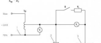
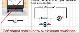
You can use the formula ΔU/I and do the calculations using an ammeter and voltmeter. This method measures the transient parameters of the contacts of high-power power switches. To do this, the ammeter is connected in series with the contacts, and the voltmeter in parallel. A ballast resistor is added in front of the ammeter, the parameters of which are selected so that the operating current of the contacts corresponds to the contact resistance current (taking into account the requirements of the PUE).
This procedure is quite cumbersome. It is advisable to use a milliohmmeter.
When choosing an ohmmeter, the following circumstances should be taken into account:
- The measurement limits must be within the control range of the device.
- The lower limit of the ohmmeter range should start from 10 μΩ.
- The measurement error should not exceed 0.5%.
There are special instruments designed to measure the contact resistance of contacts. The above requirements are already taken into account in such devices. One of the meters is shown in Figure 4. The measurement result is displayed directly on the digital display.
Rice. 4. METREL measuring device
When taking measurements, contact contamination and the operating temperature of the unit should be taken into account. The presence of third-party inclusions on the contact areas, as well as low temperature, can distort the meter readings upward. To obtain the most realistic parameters, it is necessary to select currents and voltages that are close in value to the nominal values characteristic of a particular disconnector. It should also be remembered that the contacts have an initial temporary resistance, which decreases after warming up.
There are professional measuring instruments that can adjust the output power within fairly large limits. They provide higher measurement accuracy.
Definition
In an electrical circuit, where two or more conductors touch, an electrical transition contact, or conductive junction, is created through which current flows from one part to the other.
With simple application, the contacting surface of the connected conductors does not provide good contact. The actual contact area is several times smaller than the entire contact surface, confirmation of which can be seen using a microscope. Due to the small contact area, the contact connection gives a very noticeable resistance when current passes from one surface to another and is called transition contact resistance. The contact resistance itself is a priori greater than the resistance of a solid conductor of the same shape and size.
Causes of the phenomenon
Connecting contacts combine two or more conductors in an electrical circuit. At the junction, a conductive contact is formed, as a result of which current flows from one area of the circuit to another.
If the contacts are placed on top of each other, a good connection will not be ensured. This is explained by the fact that the surface of the connecting elements is uneven and the touch is not carried out over their entire surface, but only at some points. Even if you carefully sand the surface, there will still be minor depressions and bumps on it.
Some books on electrical devices provide photographs where the contact area is visible under a microscope and is much smaller than the total contact area.
Due to the fact that the contacts have a small area, this provides significant transition resistance for the passage of electric current. Transient contact resistance is a value that occurs at the moment the current passes from one surface to another.
In order to connect the contacts, various methods of pressing and fastening the conductors are used. Pressure is the force with which surfaces interact with each other. Mounting methods are:
- Mechanical connection. Various bolts and terminal blocks are used.
- Contact occurs due to the elastic pressure of the springs.
- Soldering, welding and crimping.
Factors that cause
Contact resistance connects individual sections of the circuit to each other. At the junction, a mutual contact of current conduction is formed. Through this section, current from one branch can enter another. If you simply put the wires on top of each other, there will be no reliable connection. This is due primarily to the fact that the surface, no matter how smooth it may seem, consists of irregularities. With multiple magnification, this can be seen even on perfectly ground and polished materials.
You may be interested in this Required indoor illumination
Important! In practice, it will become clear that the area of real contact is much smaller than the visual one.
Another factor in the occurrence of junction resistance is the film resulting from the oxidation of the conductor metal. Such films prevent the current from moving and tighten its direction at the points of contact. It is impossible to completely get rid of this, since its value is always greater than the resistivity of the conductor metal.
Touch spots and uneven contacts under a microscope
Recording results
Upon completion of measurements of the transient characteristics of the entire grounding system, the customer of the work must be given a protocol for measuring and checking the metal connection, drawn up according to the established template.
This document must contain the following information:
- name and geophysical data of the electrical device or installation under study;
- the number of contacts included in it that have passed the test;
- the value of the maximum resistance of the entire measured chain.
If there are any deviations in the parameters and condition of the elements of the equipment being examined (lack of normal grounding or non-compliance of its parameters with generally accepted rules), the detected violations are also recorded in the metal communication measurement protocol.
It is worth noting that metal communication is the most important indicator of the safety of operation of existing electrical installations.
If its parameters do not meet the requirements of the standards, measures should be taken to eliminate this deficiency (organize the broaching of bolted connections, disassembling and cleaning of contacts, and so on).
But if these actions do not lead to the desired result, the entire working protective grounding chain should be updated.
The concept of transient electrical resistance in electrical contacts
Transitional electrical resistance
is the resistance that occurs at places where current passes from one wire to another or from a wire to any electrical device, in the presence of poor contact, for example, at the places of connections and ends of wires, in the contacts of machines and devices.
When a load current passes through such places, a certain amount of heat is released per unit time, the magnitude of which is proportional to the square of the current and the resistance of the transition contact
, which can heat up to a very high temperature.
If heated contacts come into contact with flammable materials, they may ignite, and if an explosive system is present, an explosion may occur. This is the fire danger of transient contact resistances, which is aggravated by the fact that places with the presence of transient resistance
are difficult to detect, and protective devices of networks and installations, even correctly selected, cannot prevent the occurrence of fires, since the current in the circuit does not increase, but heating section with transition resistance occurs only due to an increase in resistance.
Analysis and presentation of test results.
The primary entries in the workbook must contain the following data:
- measurement date
- temperature, humidity and pressure
- name, type, serial number of equipment
- nominal data of the test object
- test results
- external examination results
- the circuit used
All test data are compared with the requirements of the RD, and based on the comparison, a conclusion is issued on the suitability of the object for operation. Based on the test results, a protocol of the established form is filled out, in accordance with the requirements of the ND (GOST R 17025-2006) and agreed with the SZU of Rostechnadzor. Measurement data taken at elevated (low) ambient temperatures do not need to be reduced to the factory data temperature or to any specific, standardized temperature. The exception in this case is the results of measuring the dielectric loss tangent, since the normalization of the tangent value in ND is carried out at a temperature of 20 °C.
(6^
k.
and
(?)
Z^per — ±1.96
| 2L? 4 • 0,36/? ^ | = ±8,11% .If the condition Rn < 0.05 Rnep is met and the values of Rn are not taken into account when calculating the value of Lper, then the error interval is determined by the formula Z^per — ± 1.96 5 R, RI • 1002 K\•Rlр (4) The error limit is assessed in accordance with the requirements of this standard using the formula 5 R, lane |
Purpose of measurements
To quantify the parameter under consideration, special techniques have been developed that involve measuring the metal bond in the contact zone of the elements of the grounding system. The tests carried out here aim to:
- checking the serviceability of conductors connecting individual grounding elements (including the potential equalization system);
- assessment of the condition of their insulating coating;
- identifying the presence or absence of potential on grounded parts of electrical installations.
To measure metal bonding parameters, specialists from laboratories that have the right to conduct such tests (holding the appropriate certificate) must be involved in the work.
General procedure for checking contacts
Checking for metal connections, first of all, involves an external inspection of the elements of the protective system with a simultaneous assessment of the condition of all existing electrical joints.
During this inspection, the welded joints are first lightly tapped with a small sledgehammer (to check their mechanical strength).
Then the existing bolted or terminal contacts are checked for the quality of their tightening and the absence of any visible damage (chips, cracks, etc.)
One of the simplest and most reliable ways to determine whether any connection is loose or broken is to check it by touch. If the joint is clearly heated, there can be no doubt about a broken contact (weakening of the metal bond), after which it is necessary to take measures to restore it.
Upon completion of the visual and tactile examination of all existing contacts, their contact resistance is measured. Moreover, in addition to the welding points, the entire openly mounted chain of bolted or terminal joints, forming a grounding loop, is subject to control inspection.
Upon completion of the visual inspection, specialists invited by the customer conduct testing of the entire installation to ensure its compliance with the requirements of the Electrical Installation Regulations (including checking the conditions for current flow).
The technique used in this case involves sequential measurement of the contact resistance of each of the available contacts.
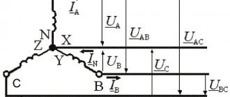
The chain being tested for metal connections includes the contact terminals of the GZSh (main grounding bus), on which the PE conductor and grounding buses of the equipment are closed, as well as connection points to the ground electrode.
According to current standards, the resistance of contacts (whether welded, bolted or terminal) should not exceed a certain level for the metal connection to be reliable. To ensure the indicator specified by the standards, the cross-sectional area of the protective conductors must correspond to the data in Table 1.7.5 of the PUE
To ensure the indicator specified by the standards, the cross-sectional area of the protective conductors must correspond to the data in Table 1.7.5 of the PUE.
Why measure contact resistance (TS)
Electrical installations (ES), as well as housings of electric motors, generators, transformers and other converters must be grounded. The grounding device is connected to the equipment and the power plant using a bolted connection, which also has a PS.
To ensure reliable operation of the protective shutdown in the event of a short circuit of alternating current to the housing, the substation must be checked periodically.
The results of PS testing make it possible to understand the probability of electric shock to a person, and whether there is a danger of equipment fire when the temperature rises on bad contacts. High PS increases the response time of protective equipment.
What is contact resistance
Transition resistance is the resistance that occurs in places on a conductor where current passes from one wire to another or from a conductor to an electrical device. This happens in cases where there is a poor connection or contact of the wires.
Wire contact options
Based on the laws of physics, in such places, when a load current passes, a certain heat is released. Its value is equal to the square of the passing current divided by the resistance of the contact point. Such places can reach quite high temperatures and, if they come into contact with materials that are susceptible to burning or melting, can cause a fire and unstable operation of the equipment.
Note! It is these contacts that are the main cause of fire situations, explosions and short circuits. The danger also arises due to the fact that such contacts are difficult to detect, and the mechanisms for protecting networks and devices, even if they are modern, cannot always prevent an emergency.
Test method
Contact with the main grounding bus can be bolted or welded. Checking metal connections requires an accurate instrument - a milliohmmeter, capable of measuring values of 0.01 Ohm and more accurate, but not vice versa. The measurement is carried out with a multimeter, if the latter meets the accuracy and sensitivity class. Devices must be verified. It will not be possible to check with a regular dial; it will show the presence of a contact, but its quality will remain unknown.
Checking and measuring metal connections begins with an external inspection of the entire installation, focusing on:
- Presence of breaks in grounding buses and wires. They can crack, tear, be destroyed by corrosion, etc.
- Quality of bolted connections. All bolts must be securely tightened, and the bars and cable lugs must not move, i.e. should not move under any force applied.
- Quality of welded joints. They are additionally tapped with good, but not too strong, hammer blows. This is done to detect cracks, the main thing is not to damage serviceable components.
How is the check performed? Each metal element of the structure must be grounded:
- racks and metal frames;
- load-bearing elements;
- marching stairs;
- lifting mechanisms;
- trays in which the wires are located;
- cable galleries;
- electrical panels;
- welding stations;
- panel doors and so on.
In order to measure resistance, the first probe is placed on the main grounding bus, usually it is marked with green paint with short yellow stripes, and the second probe is placed on the metal connection element with which they plan to measure. There must be a minimum number of connections from the final node or mechanism to the main gearbox.
The resistance of one transition contact should be 0.01 Ohm, its permissible excess is 20%. If there are several transition contacts from the element being measured to the main ground bus, then their total resistance should be no more than 0.05 Ohm. If the measurement results differ from the standard values, the contact should be improved.
For bolted ones - either just broaching, or disconnecting, cleaning adjacent planes and broaching, bringing the resistance up to standard, if the previous did not help. If metal elements are connected not by buses, but by a flexible wire, you should also check the wire for a break, because the resulting metal bond resistance in this case increases. Welding connections must be restored. After these procedures, you need to check the resistance again.
The standards for metal bond measurements and their results are discussed in detail:
- PUE-7, section 1.7;
- PTEEE, p.p. 26, 28;
- GOST R 50571.16;
- GOST 12.2.0-75, clause 3.3.7;
Standards according to PUE 7
The rules provide for compliance with important parameters, including acceptable values for contact transitions. DC resistance measurements are carried out when testing disconnectors and separators. The standards for PUE 7 require that the readings of values for separators and disconnectors designed to operate at voltages from 110 kV correspond to the manufacturer’s data.
According to the rules of PUE 7 for disconnectors of the RON3 type, designed for a rated voltage of 400 - 500 kV (at a rated current of 2000 A), the transition resistance should not exceed 200 μOhm. For OSR (110 – 220 kV/600 A, the contact resistance should be 220 μOhm.
Requirements for other types of separators used in networks 110 – 500 kV:
- A rated current of 600 A corresponds to a resistance of 175 μOhm;
- 1000 A – 120 µOhm;
- 1500 – 2000 A – the highest permissible resistance is 50 μOhm.
Measurements are made between the “contact input” point and the “contact output” terminal.
The influence of the built-in current transformer (CT) on the measurement of Rac of tank circuit breakers
When the measuring current is supplied through the pole of the tank switch, a transient process occurs in the secondary winding of the CT, which manifests itself in the induction of a voltage pulse into the primary circuit, which gradually decreases to zero. This changing voltage is summed up by the voltage drop across Rac, created by the measuring current, and is perceived by the microohmmeter as an additional (introduced from the secondary winding of the CT) resistance connected in series with Rac. and changing over time. The decay time of the transient process of the drop in the introduced resistance depends on many factors and can vary from 1.0 to 60 s. The transient process in a circuit containing a CT occurs not only when the current is turned on, but also when it is turned off.
Measurement - Contact Resistance
Measuring transient resistance is auxiliary and is necessary to monitor the condition of contacts when testing for resistance to short-circuit currents and mechanical wear resistance.
Measuring the transient resistance of contact connections is carried out using microohmmeters or contact meters, i.e. special instruments for measuring low resistances. These devices have special contact tips of the probes, which are pressed against the conductive elements on both sides of the contact connection being tested. Potential tips are connected to the side of the resistance being tested, and current probe tips are connected to the outside. The designations of potential (P) and current (T) tips are marked on the handles of the probes. The quality of the contact connection is assessed by comparing the resistance value of the section with the contact connection with the resistance value of the current-carrying element in the section, the length of which is equal to the section with the contact connection being tested.
The measurement of the transition resistance of the rail track is carried out with the MS-08 device. Before starting measurements, the section of the rail track under study is electrically isolated from the rest of the route by removing the middle busbars of the track throttles.
Measurement of the transition resistance of the rail track is carried out with the MS-08 device. Before starting measurements, the section of track under study is electrically isolated from the rest of the route by removing the middle busbars of the track chokes. The following can be used as a grounding electrode: in a tunnel with a cast iron finish - any structure that has a metal connection with the tubing; in a tunnel with reinforced concrete finishing there is a metal bus connecting the cable brackets.
Measuring the transient resistance of contacts of switching devices is carried out at direct current using one of the following methods (see GOST 8008 - 63, paragraphs.
| External view of the P316 bridge. |
It is convenient to measure the transient resistance of soldering armature windings of DC machines and similar measurements using microohmmeters.
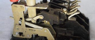
By measuring the contact resistance of the switch, its reliability is checked, since increased contact resistance can lead to overheating of the contacts, their melting and failure of the switch. The magnitude of the transition resistance of the switch contacts depends on the type of switch.
By measuring the contact resistance of the switch, its reliability is checked, since increased contact resistance can lead to overheating of the contacts, their melting and failure of the switch.
The contact resistance of the contacts of each phase is measured. If during routine repairs the contact resistance exceeds the norm and has more than doubled the value measured during major repairs, the contacts must be improved.
To measure the contact resistance of contacts, a certain intrinsically safe ohmmeter M-372 I can be used. In Fig. 58 shows an ohmmeter, the modification of which was carried out by the Severodonetsk Chemical Plant on the recommendation of the Gpproniselectroshakht Institute on the basis of the commercially produced ohmmeter M-372. It consists of its own device, in the housing of which there is a power source (MTs-4k battery), and connecting wires with clamps at the end.
| Circuit for measuring the resistance of the switch contacts (voltage drop method). |
When measuring contact resistance using a bridge (Fig. 126), the value of contact resistance is determined by direct reading on the bridge scale.
According to the Standards, measurement of the transition resistance of contacts of prefabricated and connecting busbars can be carried out only in installations with a rated current of 1,000 A or more and selectively for 5 - 10% of contacts.
| An example of determining the coefficient p based on the results of measuring the contact resistance on an existing pipeline. |
How to measure contact resistance correctly
There are certain rules that describe the correct measurement of Rn for switching devices. These include circuit breakers, all kinds of disconnectors and buses.
There are several measurement methods:
- a method when the counting is carried out directly and directly;
- using a multimeter (you can also use an ammeter or voltmeter);
- a method for measuring the unstable static behavior of a junction resistance.
Note! The first point involves the use of instruments for direct calculation with an error of less than 10%. More often it is used to measure Rn of a contact connection. The contacts are not cleaned before measurement. They are connected to the terminals of the devices. At the same time, moving devices and opening contacts is contraindicated.
You may be interested in this: How to calculate the resistance of a conductor
Formula for unstable static joint venture
In the second method, the magnitude of the voltage drop is determined at a fixed current value at the junction that is being tested. The error of any device in a measuring system of this kind is no more than 3%. Initially, the resistance value is selected several times greater than expected. The calculation is performed using the formula: Rп = UPV2/IPA, where UPV2 is the figure shown by the PV2 voltmeter in V; IPA is the current measured by the ammeter PA in Am.
The static instability of the junction resistance is determined based on the root mean square change in Rn determined through repeated measurements. The error of such measurements is +/- 10%.
List of devices for measuring SP