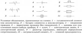
Hatching of concrete on drawings (cement, expanded clay concrete, aerated concrete) - symbol
Hatching of concrete is a symbol for various materials in drawings in accordance with current GOSTs.
Thanks to the shading on any construction diagram, you can easily determine the type of building material without the need for additional documents and explanations. In this way, it is possible to significantly simplify the process of designing and constructing various types of objects.
Hatching concrete on drawings is an opportunity to unify the basic designations regarding materials, which will be understandable to any designer or builder. Concrete is shaded in a certain way (like all other materials), the type of designation depends on the presence/absence of reinforcement and other factors.
Hatching of aerated concrete GOST
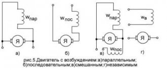
3. Expanded steel
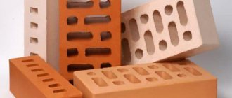
4. Masonry of building and special bricks, clinker, ceramics, terracotta, artificial and natural stones of any shape, etc.
1. (Deleted, Amendment No. 1).
2. To clarify the type of material, in particular, materials with the same type of designation, the graphic designation should be accompanied by an explanatory inscription in the drawing field.
3. In special construction design drawings for the reinforcement of reinforced concrete structures, designations according to GOST 21.501 should be used.
4. The designation of the material on the view (facade) is allowed not to be applied completely, but only in small areas along the contour or spots inside the contour.
5. Oblique parallel hatching lines should be drawn at an angle of 45 ° to the contour line of the image (Fig. 2 a) or to its axis (Fig. 2b), or to the lines of the drawing frame (Fig. 2).
If the hatch lines attached to the lines of the drawing frame at an angle of 45° coincide in direction with the contour lines or center lines, then instead of an angle of 45°, an angle of 30° or 60° should be taken (Fig. 3 and 4).
Hatching concrete according to GOST standards
How is reinforced concrete shading done correctly in drawings? Are there any standards establishing the way of designing sections and types of building structures? We have to find answers to these and some related questions.
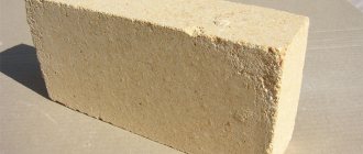
This is what concrete looks like in cross section. How is it indicated on the drawings?
Information sources
They will serve us as:
- GOST 3455-59.
- GOST 2.306 - 68, which replaced it.
Investigation
As it turned out much later, the drawing teacher simply did not know about the new standard adopted after he received higher education and taught schoolchildren the same way he himself was taught.
GOST 3455 - 59
The standard came into force on January 1, 1959 and was canceled exactly 12 years later, on January 1, 1971. Its title is “Drawings in mechanical engineering. Hatching in sections and sections.”
We are, of course, interested, first of all, in the material designation system adopted in the document.
Designations from the old standard.
GOST 2.306 - 68
This is how concrete began to be designated after the adoption of the new standard.
When making a drawing with your own hands according to GOST, you need to adhere to several rules:
- Oblique lines are drawn at an angle of 45 degrees.
However: this angle can be maintained not only relative to the drawing frame, but also relative to the axis or contour of the image.
On all sections of one part, the hatching step is the same.
So, according to the current regulatory documents, the instructions for shading concrete in the drawing are quite clear: it is indicated by dash-dotted lines. What happens if you use an outdated designation?
Fortunately, the cost of error is not too high: according to the document we just studied, when constructing drawings it is allowed to use symbols not provided for by it. You just need to explain them in the drawing.
GOST R 21.1207-97
As is easy to see, we did not find a valid GOST for shading reinforced concrete. The designation was present in the old document, but disappeared in the new one.
So what to do when constructing a drawing? Take advantage of the loophole with an arbitrary material designation and a footnote at the bottom? Or do some rules still exist?
The answer can be found in a rather unexpected place - the standard regulating symbols in road construction, when constructing road drawings.
Kawabanga! Sand concrete m150: technical properties and application
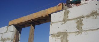
Reinforced concrete is actively used in road construction. The photo shows the Branicky bridge in Prague.
Along with asphalt, waterproofing materials and bulk soil, the document includes:
Designations according to GOST R 21.1207-97.
Conclusion
We hope that our material answered all the reader’s questions related to the designation of concrete in the drawings. As always, additional topical information can be found by watching the video in this article. Good luck!
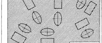
Concept of aerated concrete
Aerated concrete is one of the types of cellular concrete. It is made from a mixture of sand, lime, cement, water and a gas-forming agent, most often aluminum powder.
As a result of the reaction of the latter with quicklime, the solution swells. The result is a material filled with cells. This structure gives aerated concrete special properties and qualities, which we will consider below.
First, let’s figure out what aerated concrete is.
Types of material and scope of application
Depending on the purpose, in accordance with GOST 25485-89, aerated concrete can be:
- Thermal insulation, density 300-400. It has a low thermal conductivity coefficient and is used exclusively as a material for insulation, since such products cannot withstand any loads other than their own weight due to their low density.
- Structural and thermal insulation. Its density varies from 500 to 900. It is more durable and is used for the construction of building walls and partitions. This type of aerated concrete is most common among private developers.
- Structural. The most durable type. Its density is 1000-1200. It is used for the construction of buildings up to 3 floors high.
However, the thermal conductivity coefficient increases significantly, so this material requires additional insulation.
Using the table, let us consider the relationship between the strength of products and their thermal conductivity.
Strength and thermal conductivity of aerated concrete:
| Type of aerated concrete | Strength grade | Coefficient of thermal conductivity |
| Thermal insulation | D300 | 0,09-0,11 |
| D400 | 0,11-0,12 | |
| Structural and thermal insulation | D500 | 0,12-0,13 |
| D600 | 0,14-0,15 | |
| D700 | 0,18-0,21 | |
| D800 | 0,21-0,23 | |
| D900 | 0,23-0,26 | |
| Structural | D1000 | 0,23-0,28 |
| D1100 | 0,28-0,34 | |
| D1200 | 0,29-0,38 |
Since we are talking about the use of the material, it was worth mentioning how aerated concrete and concrete in general are indicated in construction projects on the drawings. Hatching of aerated concrete in the drawings is indicated in the form of dotted strokes - lines at an angle. This is clearly shown in the photo below.
Also, depending on the type of hardening, aerated concrete is divided into autoclave and non-autoclave. Autoclaved aerated concrete (synthetic hardening aerated concrete) is distinguished by the fact that the final stage of production is the processing of products in an autoclave under high temperature and pressure.
The process of releasing material occurs in a fairly short time. Non-autoclaved aerated concrete (hydration-hardening aerated concrete) hardens under natural conditions. Sometimes it is slightly heated in special machines to a low temperature in order to speed up the process. Such aerated concrete reaches brand strength within 28 days.
It is somewhat inferior in characteristics to its autoclave competitor. This concerns, first of all, strength, frost resistance, thermal conductivity and durability.
Comparison of synthetic and hydration-hardening aerated concrete:
| Indicator name | Value for autoclaved aerated concrete | Value for non-autoclaved aerated concrete |
| Thermal conductivity of dry products | From 0.09 to 0.38 | From 0.11 to 0.40 |
| Frost resistance, cycles | Up to 150 | Up to 50 |
| Shrinkage, mm/m2 | 0,3 | 0,5 |
| Strength grade | From B2.5 | From B 1.5 |
| Product color | white | Grey |
| Durability, years | Up to 200 | Up to 50 |
| Brand by density | 300-1200 | 300-1200 |
According to the type of silica component, aerated concrete blocks can be made using:
- Pesce;
- Zole;
- Other secondary industrial waste.
Depending on the type of binder, aerated concrete is:
- On a cement binder;
- On slag;
- On limestone;
- On ash;
- On mixed.
The products contain 15-50% of the main component.
In accordance with the accuracy category, aerated concrete products are divided into:
- Blocks of the first category of accuracy;
- Blocks of the second category of accuracy;
- Blocks of the third category of accuracy.
GOST 2.306-68 Designations of graphic materials and rules for their application on drawings
Designations of graphic materials in sections
Designations of graphic materials in views
Rules for applying shading in drawings
Graphic designation of the material in sections and in views is shading performed with thin solid lines. The shape of the hatching in accordance with GOST 2.306-68 gives an idea of the material from which the part is made.
Graphic designation of materials in sections, depending on the type of materials, must correspond to those given in table. 1.
| Material | Designation |
| 1. Metals and hard alloys (The general graphic designation of materials in sections, regardless of the type of material, must correspond) | |
| 2. Non-metallic materials, including fibrous monolithic and slab (pressed), with the exception of those indicated below | |
| 3. Wood | |
| 4. Natural stone | |
| 5. Ceramics and silicate materials for masonry | |
| 6. Concrete | |
| 7. Glass and other translucent materials | |
| 8. Liquids | |
| 9. Natural soil |
- Composite materials containing metals and non-metallic materials are referred to as metals.
- The graphic designation of paragraph 3 should be used when there is no need to indicate the direction of the fibers.
- The graphic designation of paragraph 5 should be used to designate brick products (fired and unfired), refractories, building ceramics, electrical porcelain, slag concrete blocks, etc.
When highlighting materials and products on a view (facade), their graphic designations must correspond to those indicated in the table. 2.
| Material | Designation |
| 1. Metals | |
| 2. Corrugated steel | |
| 3. Expanded steel | |
| 4. Masonry of building and special bricks, clinker, ceramics, terracotta, artificial and natural stones of any shape, etc. | |
| 5. Glass |
- To clarify the type of material, in particular, materials with the same type of designation, the graphic designation should be accompanied by an explanatory inscription in the drawing field.
- In special construction design drawings for the reinforcement of reinforced concrete structures, designations in accordance with GOST 21.107-78 should be used.
- The designation of materials on the view (facade) is allowed to be applied not completely, but only in small areas along the contour or spots inside the contour.
Install the following designation of the mesh and backfill from any material (in cross-section), indicated in Table 3.
| Material | Designation |
| 1. Grid | |
| 2. Backfill |
Oblique parallel hatch lines should be drawn at an angle of 45 o to the image contour line (Fig. 1) or to its axis (Fig. 2) or to the drawing frame lines (Fig. 3)
| Figure 1. Hatching at an angle of 45 0 to the contour line | Figure 2. Hatching at an angle of 45 0 to the axis If the hatch lines, brought to the line of the drawing frame at an angle of 45 o, coincide with the contour lines or center lines, then instead of an angle of 45 o, an angle of 30 o or 60 o should be taken (Fig. 4 and 5). Hatch lines should be drawn slanted to the left or right, but, as a rule, in the same direction on all sections belonging to the same part, regardless of the number of sheets on which these sections are located. The distance between parallel straight hatching lines (frequency) should, as a rule, be the same for all sections of a given part performed on the same scale and is selected depending on the hatching area and the need to diversify the hatching of adjacent sections. The specified distance should be from 1 to 10 mm, depending on the hatching area and the need to diversify the hatching of adjacent sections. |
Narrow and long cross-sectional areas (for example, stamped, rolled and other similar parts), the width of which in the drawing is from 2 to 4 mm, are recommended to be completely hatched only at the ends and at the contours of the holes, and the remaining cross-sectional area - in small sections in several places (Fig. 6 and 7). In these cases, the glass hatch lines (Fig. 8) should be drawn with an inclination of 15 - 20 o to the lines of the larger side of the section contour.
Narrow cross-sectional areas, the width of which in the drawing is less than 2 mm, may be shown blackened, leaving gaps between adjacent sections of at least 0.8 mm (Fig. 9, 10).
In construction drawings, it is allowed to designate any material as metal on sections of a small area or not to use the designation at all, making explanatory notes in the drawing field.
The designation specified in paragraph 3 of the table. 1, and the designation of the backfill in the sections is done by hand.
| Figure 9. Hatching of narrow areas whose width in the drawing is less than 2 mm. | Figure 10. Hatching of narrow areas whose width in the drawing is less than 2 mm. |
For adjacent sections of two parts, you should take the slope of the hatching lines for one section to the right, for the other - to the left (counter hatching).
When hatching in a checkerboard for adjacent sections of two parts, the distance between the hatching lines in each section should be different.
In adjacent sections with hatching of the same slope and direction, you should change the distance between the hatching lines (Fig. 11) or shift these lines in one section relative to the other without changing the angle of their inclination (Fig. 12).
Figure 11. Sample of hatching of adjacent areas
Figure 12. Sample of hatching of adjacent areas
Figure 13. Sample of hatching of large areas
ESKD GOST 2. Rules for applying shading in drawings
Designations of graphic materials in sections
Designations of graphic materials in views
Rules for applying shading in drawings
The graphic designation of the material in sections and in views is shading performed with thin solid lines. The shape of the hatching in accordance with GOST 2.306-68 gives an idea of the material from which the part is made.
Designations of graphic materials in sections
Graphic designation of materials in sections, depending on the type of materials, must correspond to those given in table. 1.
Table 1. Graphic designation of materials in sections
Table 2. Graphic designation of materials on the view (facade)
| Material | Designation |
| 1. Metals | |
| 2. Corrugated steel | |
| 3. Expanded steel | |
| 4. Masonry of building and special bricks, clinker, ceramics, terracotta, artificial and natural stones of any shape, etc. | |
| 5. Glass |
Kawabanga!
Which foundation to choose from expanded clay concrete blocks Table 3. Designation of mesh and backfill made of any material (in cross-section)
| Material | Designation |
| 1. Grid | |
| 2. Backfill |
Rules for applying shading in drawings
Oblique parallel hatch lines should be drawn at an angle of 45° to the image contour line (Fig. 1) or to its axis (Fig. 2) or to the drawing frame lines (Fig. 3)
| Figure 1. Hatching at an angle of 450 to the contour line | Figure 2. Hatching at an angle of 450 to the axis |
Figure 3. Hatching at an angle of 45
If the hatch lines drawn to the drawing frame line at an angle of 45° coincide with the contour lines or center lines, then instead of an angle of 45°, an angle of 30° or 60° should be taken (Fig. 4 and 5).
Hatch lines should be drawn slanted to the left or right, but, as a rule, in the same direction on all sections belonging to the same part, regardless of the number of sheets on which these sections are located.
| Figure 4. Hatching at an angle of 300 to the drawing frame | Figure 5. Hatching at an angle of 600 to the drawing frame |
Figure 6. Hatching of narrow and long areas
Figure 7. Hatching of narrow and long areas Hatching of all symbols in this case is done by hand.
Figure 8. Hatching of narrow and long areas
| Figure 9. Hatching of narrow areas whose width in the drawing is less than 2 mm. | Figure 10. Hatching of narrow areas whose width in the drawing is less than 2 mm. |
Figure 11. Sample shading of adjacent areas
Figure 12. Sample shading of adjacent areas
For large cross-sectional areas, as well as when indicating the soil profile, it is allowed to apply the designation only at the contour of the section with a narrow strip of uniform width (Fig. 13).
Figure 13. Sample of large area shading
Designations of graphic materials in views
When highlighting materials and products on a view (facade), their graphic designations must correspond to those indicated in the table. 2.
Table 2.
Material
Designation
1. Metals
2. Corrugated steel
3. Expanded steel
4. Masonry of building and special bricks, clinker, ceramics, terracotta, artificial and natural stones of any shape, etc.
5. Glass
1. To clarify the type of material, in particular, materials with the same type of designation, the graphic designation should be accompanied by an explanatory inscription in the drawing field.
2. In special construction design drawings for the reinforcement of reinforced concrete structures, designations in accordance with GOST 21.107-78 should be used.
3. The designation of materials on the view (facade) may not be applied completely, but only in small areas along the contour or spots inside the contour
Install the following designation of the mesh and backfill from any material (in cross-section), indicated in Table 3.
Table 3.
Material
Designation
| Net |
| Backfill |
GOST 2.306-68* “ESKD. Designations of graphic materials and rules for their application on drawings"
UNIFIED SYSTEM OF DESIGN DOCUMENTATION
SYMBOLS, GRAPHICS AND RULES
THEIR APPLICATIONS ON THE DRAWINGS
IPC PUBLISHING HOUSE OF STANDARDS Moscow
Unified system of design documentation
DESIGNATIONS OF GRAPHIC MATERIALS AND RULES FOR THEIR APPLICATION ON DRAWINGS
Unified system for design documentation. Graphical designations of materials and rules for their representation
Date of introduction 01/01/71
1. This standard establishes graphic designations of materials in sections and on facades, as well as rules for applying them to drawings of all industries and construction.
(Changed edition, Amendment No. 2).
la. The general graphic designation of materials in sections, regardless of the type of materials, must correspond to the following. 1a.
(Introduced additionally, Amendment No. 1).
2. Graphic designations of materials in sections, depending on the type of materials, must correspond to those given in table. 1.
It is allowed to use additional designations for materials not provided for in this standard, explaining them in the drawing.
1. Metals and hard alloys
2. Non-metallic materials, including fibrous monolithic and slab (pressed), with the exception of those indicated below
4. Natural stone
5. Ceramics and silicate materials for masonry
7. Glass and other translucent materials
9. Natural soil
1. Composite materials containing metals and non-metallic materials are designated as metals.
2. The graphic designation of paragraph 3 should be used when there is no need to indicate the direction of the fibers.
3. The graphic designation of clause 5 should be used to designate brick products (fired and unfired), refractories, building ceramics, electrical porcelain, cinder blocks, etc.
(Changed edition, Amendment No. 1, 2).
3. Install the following designations for mesh and backfill made of any material (in cross-section), indicated in the drawing. 1.
a - mesh; b – backfill
4. When highlighting materials and products on a view (facade), their graphic designations must correspond to those indicated in the table. 2.
2. Corrugated steel
3. Expanded steel
4. Masonry of building and special bricks, clinker, ceramics, terracotta, artificial and natural stones of any shape, etc.
1. (Deleted, Amendment No. 1).
2. To clarify the type of material, in particular, materials with the same type of designation, the graphic designation should be accompanied by an explanatory inscription in the drawing field.
3. In special construction design drawings for the reinforcement of reinforced concrete structures, designations in accordance with GOST 21.501 should be used.
4. The designation of the material on the view (facade) is allowed not to be applied completely, but only in small areas along the contour or spots inside the contour.
5. Oblique parallel hatching lines should be drawn at an angle of 45° to the contour line of the image (Fig. 2a) or to its axis (Fig. 2b), or to the lines of the drawing frame (Fig. 2).
If the hatch lines attached to the drawing frame lines at an angle of 45° coincide in direction with the contour lines or center lines, then instead of an angle of 45°, an angle of 30° or 60° should be taken (Fig. 3 and 4).
Hatch lines should be drawn with an inclination to the left or right, but as a rule, in the same direction on all sections belonging to the same part, regardless of the number of sheets on which these sections are located.
(Changed edition, Amendment No. 1).
(Changed edition, Amendment No. 2).
(Changed edition, Amendment No. 4)
8. Narrow cross-sectional areas, the width of which in the drawing is less than 2 mm, may be shown blackened, leaving gaps between adjacent sections of at least 0.8 mm (drawings 8, 9).
Kawabanga! Wear of asphalt concrete pavement
In construction drawings, it is allowed to designate any material as metal on sections of a small area or not to use the designation at all, making an explanatory inscription in the drawing field.
9. Designation specified in paragraph 3 of table. 1, and the designation of the backfill in the cross-section is done by hand.
(Changed edition, Amendment No. 1).
10. For adjacent sections of two parts, you should take the slope of the hatching lines for one section to the right, for the other - to the left (counter hatching).
When shading “in a cage” for adjacent sections of two parts, the distance between the hatch lines in each section should be different.
In adjacent sections with hatching of the same slope and direction, you should change the distance between the hatching lines (Fig. 10) or shift these lines in one section relative to the other without changing the angle of their inclination (Fig. 11).
11. For large cross-sectional areas, as well as when indicating the soil profile, it is allowed to apply the designation only at the contour of the section with a narrow strip of uniform width (Fig. 12).
(Changed edition, Amendment No. 1).
1. DEVELOPED AND INTRODUCED by the Committee of Standards, Measures and Measuring Instruments under the Council of Ministers of the USSR
V.R. Verchenko, E.A. Panfilov, Yu.I. Stepanov, Ya.G. Old-timer, B.Ya. Kabakov, L.V. Matveev, N.I. Ermin, V.N. Vzorov, M.G. Aranovsky
2. APPROVED AND ENTERED INTO EFFECT by the Decree of the Committee of Standards, Measures and Measuring Instruments under the Council of Ministers of the USSR in December 1967.
3. (Deleted, Amendment No. 4)
4. Instead of GOST 3455-59 and GOST 11633-65
5. REFERENCE REGULATIVE AND TECHNICAL DOCUMENTS
Designation of the referenced technical document
6. EDITION (April 2000) with Amendments No. 1, 2, 3, approved in August 1980, September 1987, March 1989 (IUS 11-80, 12-87, 7-89)