General information
GOST shading of materials is a symbol. Using shading on the diagram, you can determine the type of building material. This is required for convenience during the construction of objects for various purposes.
Concrete is shaded from several constituent elements that are located at some distance from each other, and the lines and strokes used may intersect.
Such drawings are used during the construction of many construction projects. However, there are some nuances that must be taken into account:
- you can additionally draw up the required number of drawings and indicate explanations for individual building materials that were not taken into account during the creation of the standard;
- taking into account GOST, the designation of concrete on the drawings may be absent if this is not necessary, or it may be partially indicated - to highlight a specific object.
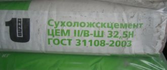
Today, several established templates are used in construction: GOST 3455–59, GOST 2306−68, GOST R 21.1207−97.
GOST 2.306-68* “ESKD. Designations of graphic materials and rules for their application on drawings"
UNIFIED SYSTEM OF DESIGN DOCUMENTATION
SYMBOLS, GRAPHICS AND RULES
THEIR APPLICATIONS ON THE DRAWINGS
IPC PUBLISHING HOUSE OF STANDARDS Moscow
Unified system of design documentation
DESIGNATIONS OF GRAPHIC MATERIALS AND RULES FOR THEIR APPLICATION ON DRAWINGS
Unified system for design documentation. Graphical designations of materials and rules for their representation
Date of introduction 01/01/71
1. This standard establishes graphic designations of materials in sections and on facades, as well as rules for applying them to drawings of all industries and construction.
(Changed edition, Amendment No. 2).
la. The general graphic designation of materials in sections, regardless of the type of materials, must correspond to the following. 1a.
(Introduced additionally, Amendment No. 1).
2. Graphic designations of materials in sections, depending on the type of materials, must correspond to those given in table. 1.
It is allowed to use additional designations for materials not provided for in this standard, explaining them in the drawing.
1. Metals and hard alloys
2. Non-metallic materials, including fibrous monolithic and slab (pressed), with the exception of those indicated below
4. Natural stone
5. Ceramics and silicate materials for masonry
7. Glass and other translucent materials
9. Natural soil
1. Composite materials containing metals and non-metallic materials are designated as metals.
2. The graphic designation of paragraph 3 should be used when there is no need to indicate the direction of the fibers.
3. The graphic designation of clause 5 should be used to designate brick products (fired and unfired), refractories, building ceramics, electrical porcelain, cinder blocks, etc.
(Changed edition, Amendment No. 1, 2).
3. Install the following designations for mesh and backfill made of any material (in cross-section), indicated in the drawing. 1.
a - mesh; b – backfill
4. When highlighting materials and products on a view (facade), their graphic designations must correspond to those indicated in the table. 2.
2. Corrugated steel
3. Expanded steel
4. Masonry of building and special bricks, clinker, ceramics, terracotta, artificial and natural stones of any shape, etc.
1. (Deleted, Amendment No. 1).
2. To clarify the type of material, in particular, materials with the same type of designation, the graphic designation should be accompanied by an explanatory inscription in the drawing field.
3. In special construction design drawings for the reinforcement of reinforced concrete structures, designations in accordance with GOST 21.501 should be used.
4. The designation of the material on the view (facade) is allowed not to be applied completely, but only in small areas along the contour or spots inside the contour.
5. Oblique parallel hatching lines should be drawn at an angle of 45° to the contour line of the image (Fig. 2a) or to its axis (Fig. 2b), or to the lines of the drawing frame (Fig. 2).
If the hatch lines attached to the drawing frame lines at an angle of 45° coincide in direction with the contour lines or center lines, then instead of an angle of 45°, an angle of 30° or 60° should be taken (Fig. 3 and 4).
Hatch lines should be drawn with an inclination to the left or right, but as a rule, in the same direction on all sections belonging to the same part, regardless of the number of sheets on which these sections are located.
(Changed edition, Amendment No. 1).
(Changed edition, Amendment No. 2).
(Changed edition, Amendment No. 4)
8. Narrow cross-sectional areas, the width of which in the drawing is less than 2 mm, may be shown blackened, leaving gaps between adjacent sections of at least 0.8 mm (drawings 8, 9).
Kawabanga! Characteristics of sand concrete grade M-500
In construction drawings, it is allowed to designate any material as metal on sections of a small area or not to use the designation at all, making an explanatory inscription in the drawing field.
9. Designation specified in paragraph 3 of table. 1, and the designation of the backfill in the cross-section is done by hand.
(Changed edition, Amendment No. 1).
10. For adjacent sections of two parts, you should take the slope of the hatching lines for one section to the right, for the other - to the left (counter hatching).
When shading “in a cage” for adjacent sections of two parts, the distance between the hatch lines in each section should be different.
In adjacent sections with hatching of the same slope and direction, you should change the distance between the hatching lines (Fig. 10) or shift these lines in one section relative to the other without changing the angle of their inclination (Fig. 11).
11. For large cross-sectional areas, as well as when indicating the soil profile, it is allowed to apply the designation only at the contour of the section with a narrow strip of uniform width (Fig. 12).
(Changed edition, Amendment No. 1).
1. DEVELOPED AND INTRODUCED by the Committee of Standards, Measures and Measuring Instruments under the Council of Ministers of the USSR
V.R. Verchenko, E.A. Panfilov, Yu.I. Stepanov, Ya.G. Old-timer, B.Ya. Kabakov, L.V. Matveev, N.I. Ermin, V.N. Vzorov, M.G. Aranovsky
2. APPROVED AND ENTERED INTO EFFECT by the Decree of the Committee of Standards, Measures and Measuring Instruments under the Council of Ministers of the USSR in December 1967.
3. (Deleted, Amendment No. 4)
4. Instead of GOST 3455-59 and GOST 11633-65
5. REFERENCE REGULATIVE AND TECHNICAL DOCUMENTS
Designation of the referenced technical document
6. EDITION (April 2000) with Amendments No. 1, 2, 3, approved in August 1980, September 1987, March 1989 (IUS 11-80, 12-87, 7-89)
Designation according to GOST 3455–59
This established template was created in the 60s, it began to be used on construction diagrams from 02/01/1962. GOST was valid until 02/02/1973. It describes drawings for mechanical engineering. The conditional values were as follows:
- non-metallic building materials - marked in the form of lines inclined to the left or right at an intersection of 90 degrees;
- metal - marked with oblique lines, maintaining the same distance;
- liquids - vertical dotted lines with tapering intervals;
- rings and cracks - a longitudinal section was used for symbolic designation;
- wood - designations were used taking into account the characteristics of wood;
- solutions were marked with horizontal hatching, and the gaps were made narrow;
- plywood - sectional section;
- unreinforced reinforced concrete structures were made in the form of sand and gravel;
- expanded clay concrete - sand gravel was applied, additionally 3 crossed lines were used, which are located in different directions;
- glass - indicated on the diagrams using strokes of three varieties and different intervals;
- reinforced concrete - oblique strokes with a sand-gravel pattern;
- brickwork - two types of lines intersecting at an angle were used.
Difference GOST 2.306−68
As already indicated, the previous system was abolished in 1973. This standard has been modified by new designation elements.
The main difference between the new shading of reinforced concrete according to GOST is the mandatory compliance and rigor of the standard. This established template has been simplified. The new system did not have any special effects, everything was clear and precise. The main changes were as follows:
- stones - depicted in the diagram as an inclined dotted line;
- tree - designated using identical arcs located at the same distance;
- ground - three strokes were used, representing a group with small intervals;
- hatching of concrete according to GOST was done using dotted lines, observing a certain slope;
- ceramic building materials and silicate - were indicated by elements that consisted of several groups, and there was a significant distance between the lines.
New graphic elements make it possible to indicate on the drawings the required building materials during the construction of buildings and other structures. This is convenient both during the production of individual elements and during the creation of various objects.
The marks are drawn with thin lines, drawing them in the required order and at a given distance. Within one schematic drawing, symbols of metal products should stand out from other building materials. Therefore, more space must be left between the lines when specifying these elements.
Parallel lines are made while maintaining equal intervals for sections of a certain part of structures that have the same scale. For different cross-sectional areas this step is 2−12 mm.
During the creation of the new shading system, the old GOST was canceled. The newly established template of 1973 indicates the same production stages as in GOST 1962. The first version of GOST is invalid.
In this case, the standard that was adopted in 1962 is reviewed for reference to other accepted established standards.
Features of GOST from 1973
There are also other features of the standard. These rules are expressed in the following points:
- explanations must be provided;
- if there is a similarity in the drawing of various elements during which various materials are described, then one cannot do without auxiliary information;
- façade building materials are not indicated in full; in this case, it is only necessary to partially indicate the outline;
- features of shading of building material on the diagram are indicated in GOST 21 .107−78;
- There are no designations for reinforced concrete structures in the standard, so a special template was developed for them.
There are also certain rules that the 1973 standard provides for. Hatching of concrete is carried out in this way:
- Small sections are marked with strokes. This designation is similar to the description of a metal.
- Lines that need to be drawn at an angle must be drawn with a clear slope of 45 degrees. The angle must be determined taking into account the landmark not only of the diagram itself, but also in compliance with the contour of the image.
- In adjacent planes, lines must be drawn at different angles.
- Hatching is left-handed or right-handed, but in one design the angle for the sections should be the same.
- Long narrow cuts do not have to be completely shaded; shading can be only along the edges or in several areas that are chosen in any form. Sections with a thickness of no more than 3 mm are completely shaded.
The rules provided for by the standard must be complied with.
ESKD GOST 2. Rules for applying shading in drawings
Designations of graphic materials in sections
Designations of graphic materials in views
Rules for applying shading in drawings
The graphic designation of the material in sections and in views is shading performed with thin solid lines. The shape of the hatching in accordance with GOST 2.306-68 gives an idea of the material from which the part is made.
Designations of graphic materials in sections
Graphic designation of materials in sections, depending on the type of materials, must correspond to those given in table. 1.
Table 1. Graphic designation of materials in sections
Table 2. Graphic designation of materials on the view (facade)
| Material | Designation |
| 1. Metals | |
| 2. Corrugated steel | |
| 3. Expanded steel | |
| 4. Masonry of building and special bricks, clinker, ceramics, terracotta, artificial and natural stones of any shape, etc. | |
| 5. Glass |
Kawabanga!
Concrete m450; composition and scope of application of the material Table 3. Designation of mesh and backfill made of any material (in cross-section)
| Material | Designation |
| 1. Grid | |
| 2. Backfill |
Rules for applying shading in drawings
Oblique parallel hatch lines should be drawn at an angle of 45° to the image contour line (Fig. 1) or to its axis (Fig. 2) or to the drawing frame lines (Fig. 3)
| Figure 1. Hatching at an angle of 450 to the contour line | Figure 2. Hatching at an angle of 450 to the axis |
Figure 3. Hatching at an angle of 45
If the hatch lines drawn to the drawing frame line at an angle of 45° coincide with the contour lines or center lines, then instead of an angle of 45°, an angle of 30° or 60° should be taken (Fig. 4 and 5).
Hatch lines should be drawn slanted to the left or right, but, as a rule, in the same direction on all sections belonging to the same part, regardless of the number of sheets on which these sections are located.
| Figure 4. Hatching at an angle of 300 to the drawing frame | Figure 5. Hatching at an angle of 600 to the drawing frame |
Figure 6. Hatching of narrow and long areas
Figure 7. Hatching of narrow and long areas Hatching of all symbols in this case is done by hand.
Figure 8. Hatching of narrow and long areas
| Figure 9. Hatching of narrow areas whose width in the drawing is less than 2 mm. | Figure 10. Hatching of narrow areas whose width in the drawing is less than 2 mm. |
Figure 11. Sample shading of adjacent areas
Figure 12. Sample shading of adjacent areas
For large cross-sectional areas, as well as when indicating the soil profile, it is allowed to apply the designation only at the contour of the section with a narrow strip of uniform width (Fig. 13).
Figure 13. Sample of large area shading