IEE is a source of alternating current voltage, see. In the second case, the elements of the device are placed in different parts of the electrical circuit, and each of them is assigned an alphanumeric designation. The connections between individual elements are specified and deciphered. Graphic designations of elements and electrical communication lines connecting them should be placed on the diagram so as to provide the best understanding of the structure and operation of the electrical device. "Electronics" for an electrician. Part 1.
When approaching the contacts, each wire is depicted as a separate line.
How is the construction done? The form of the connection table can be made in two versions, shown in Fig. 6.
The ship's documentation for each electric drive contains a schematic diagram with a specification and explanatory note and electrical wiring diagrams. Organizational and legal form of operation of the enterprise.
On the contrary, diagrams in which symbols of elements, communication lines are aligned horizontally and vertically, communication line routes are laid out economically, are easy to read and their action is understood much faster. It depicts a set of links of an object, the connection between them.
Data is usually placed on a free field or near graphic symbols. Compared to a block diagram, it reveals in more detail the functions of the individual elements of the device.
How to Read Electrical Diagrams
Our VKontakte group
Naturally, it reflects the properties of the power plant much more completely than the block diagram. Tags: SAEP , feature articles , technical dictionary , electrical circuits , electric drive An electrical diagram is a graphic representation of the connections between the electrical elements of an installation, allowing one to understand the principle of operation of an electrical device.
Along with power controllers, command controllers are used in contactor control circuits for lifting mechanisms of winches and cranes. Guidelines for reading electrical diagrams consist of recommendations on the accepted order of sequence for studying an electrified installation.
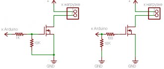
The contactor coil K1 receives power, and the contactor, having activated, connects the electric motor to the network with its closing contacts. Device M.
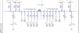
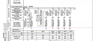
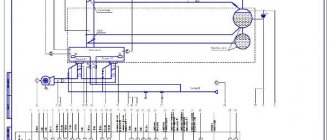
Another type of circuit diagrams reflects drive control, line control, protection, interlocks, and alarms. The type and number are a mandatory part of the symbol, but the indication of the function is optional. One of them displays the primary power networks.
Block diagrams of computers, enterprises and management - what are their features? In the diagram, using a system of positional designations, all elements depicted on it are unambiguously identified.
4.1. Electrical structural diagram (E1)
It is allowed to place technical data of the product on the diagrams in the form of diagrams, tables or text. The difference between a structural diagram and a functional diagram Thus, the difference between structural and functional diagrams is that the structural diagram outlines the overall picture of the device and indicates the location of functional elements and links, while the functional diagram more accurately describes the position of the elements in the nodes, the interaction between the elements of the diagram.
The scale of the company is calculated in production volume, number of personnel, cash income. Graphic designations of elements should be made with lines of the same thickness as the communication lines. The connection table can be made in the form of an independent document in A4 format with the main inscription GOST 2. Then you should familiarize yourself with the power circuit diagram, starting with the current source.
In onshore installations, where the power of the supply network is many times greater than the power of the electric motor being switched on, it is possible to directly turn on electric motors of higher power than in ship conditions, where the power of power plants is limited. To simplify the diagram graphics, it is possible to merge individual wires running in one direction on the diagram into a common line. The recording of elements included in each device functional group begins with the corresponding header. Mefodieva L. How to read a diagram. Part 7. Power sequence for Desktop.
Managment structure
The management structure is of particular importance in the structure of any production. In general, it is a set of interconnected management links. Its parts: the number of controls, the order of their interaction, their functional load.
Linear structure
The most popular and simplest is the linear structure. It is also called bureaucratic-hierarchical. To put it very simply, the leader is at the head, and all the rest are subordinates. Moreover, one manager may have several subordinates, who in turn manage their subordinates, etc.
Note! Large enterprises have 3-4 even more levels of hierarchy.
With this scheme, each individual link and subordinate have a single leader. It is from him that the commands to complete a particular task come. Direct managers are responsible for work results. In this case, decisions are transferred from top to bottom, with a lower-level manager reporting to a senior manager. The convenience for the employee is that higher ranks do not have the right to jump over the head of their immediate superior, regardless of their status. That is, it is not within their competence to give instructions to the employee.
In a linear structure, the management system is combined according to production characteristics, taking into account the degree of concentration of production, the range of manufactured goods, and technological features.
This structure is logical and more formalized, but less flexible. The head of each level has limited power, which makes it impossible to solve highly specialized problems.
Advantages
- There is a clear limitation of responsibility and competence.
- Ease of monitoring task completion.
- Decisions can be made quickly and economically.
- Simplicity of hierarchical communication, with a clear description of the assigned tasks.
- Personal responsibility for results.
Flaws
- Requirements for a manager to have a high professional level.
- Difficulty in communication between performers.
- The manager has too narrow a specialization.
- Authoritarian management style.
- A heavy burden on any manager, regardless of the hierarchical level.
Note! This type of control scheme is used not only in manufacturing enterprises. It is key in all government structures, including the housing and communal services system, government inspection structures, for example the Tax Service.
What are block diagrams?
M stand
Graphic designations of elements and electrical communication lines connecting them should be placed on the diagram so as to provide the best understanding of the structure and operation of the electrical device.
Such schemes are performed for the disconnected position of the product.
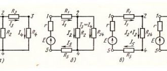
They define the main functional parts that a product, enterprise or division will have. For all elements of the circuit, its alphanumeric designation should be indicated [2, p. The digits of the serial numbers, which indicate the numbering of identical elements, must be made in the same font size with the letter designations of the element. Schematic diagrams depict all electrical elements and connections between them to explain the principles of operation of an electrified installation.
We recommend: Electrical equipment testing standards
Another type of circuit diagrams reflects drive control, line control, protection, interlocks, and alarms. The diagram should show the product, its input and output elements, connectors, clamps, etc. Interconnection lines should be made with a thickness of 0.2 to 1.0 mm.
While the block diagram is a set of formal models of the functional parts of the power plant, the circuit diagram is a set of electrical models of these parts. The diagrams take into account the technology of installation of electrical apparatus and instruments, as well as the possibility of laying cable routes throughout the vessel, taking into account the requirements of the register.
4.2. Electrical functional diagram (E2)
The positional designation of elements in the general case consists of three parts of GOST 2. For example, the code for the connection table to the electrical connection diagram TE4. The functional parts of the device and the connections between them are indicated in the form of special graphic symbols. If data on wires and cables is indicated near the lines depicting wires and cables, it is allowed not to assign designations to the wires and cables.
Connection diagrams also include connections between different mounting blocks that are part of one complete device, for example, connections within a control panel exceeding 4 m in length; the maximum size of the mounting block within which the manufacturer makes all the connections itself is 4 m It is very important in reversible electric drives to exclude the possibility of simultaneous activation of contactors K1 and K2, since this leads to a short circuit of the power network with the main contacts. The development of a schematic diagram of a functional element consists in choosing one of the known schemes that most fully satisfies the set of technical and economic requirements with maximum simplicity and reliability. Lesson #37. How to Read Circuit Diagrams
Electrical structural diagrams
6.3.1 Electrical structural diagram (code E1) – a diagram that defines the main functional parts of the product, their purpose and interconnections.
These diagrams are developed during product design at stages preceding the development of other types of schemes, and they are used for general familiarization with the product.
6.3.2 The electrical structural diagram shows all the main functional parts of the product (elements, devices and functional groups) and the main relationships between them.
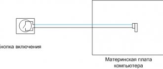
The functional parts of the product in accordance with GOST 2.721 are depicted in the form of rectangles with dimensions of 10x10 or 10x15 mm or UGO, given in the relevant standards.
6.3.3 The graphical construction of the diagram should give a clear idea of the sequence of interaction of the functional parts of the product. On the interconnection lines, it is recommended to use arrows to indicate the direction of the processes occurring in the product.
6.3.4 The diagram must indicate the names of each functional part of the product if a rectangle is used to designate it. In this case, the names are entered inside the rectangles in accordance with Figure 6.13.
Figure 6.13 – Example of an electrical structural diagram
If there are a large number of functional parts, instead of a name, it is allowed to put serial numbers to the right of the image or above it, usually from top to bottom in the direction from left to right. In this case, the names are indicated in a free-form table placed on the diagram field in accordance with Figure 6.14.
| Serial number | Name |
| 1 | Antenna |
| 2 | Oscillatory circuit |
| 3 | Detector |
| 4 | Amplifier |
| 5 | Power supply |
| 6 | Telephone |
Figure 6.14 – Electrical structural diagram of a direct amplification receiver
It should be noted that when using digital designations instead of the names of functional parts, the clarity of the diagram is significantly deteriorated, since the purpose of each functional component is clarified not only from the image, but also using the list given in table.
ATTENTION: IN STUDENT WORKS AND PROJECTS WHEN PRODUCING ELECTRICAL STRUCTURE DIAGRAMS, THE NAMES OF FUNCTIONAL DEVICES ARE RECOMMENDED TO BE ENTERED INSIDE THE RECTANGLES.
6.3.5 On the diagram it is allowed to place technical characteristics of functional parts, explanatory inscriptions, diagrams or tables that determine the sequence of processes in time, as well as indicate parameters at characteristic points (voltage values, currents, pulse forces, etc.).
6.3.6 In diagrams of simple products, functional parts are arranged in a straight chain in accordance with the direction of signal propagation from left to right.
It is recommended to design circuits of products containing several signal propagation channels in the form of parallel horizontal chains. Additional and auxiliary circuits must be removed from the main circuits.
To improve clarity, it is recommended to place the main circuits horizontally, and additional and auxiliary circuits vertically or horizontally between the main circuits.
An example of an electrical structural diagram is given in Appendix M of this manual.