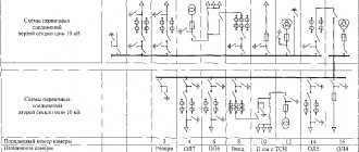
In addition to showing the individual wires, it is also important to show additional details of the electrical circuit on the drawing.
ESKD is a Unified System of Design Documentation.
In particular, it is necessary to connect to the local network of a house with an AVR: Photo - a house with an AVR To develop for free a single-line power supply diagram for a child care facility, private buildings, garages, houses, apartments, kiosks, a multi-storey residential building, a SNT plant, crew cars, you will need an ESKD . Single line diagram designer. Description of work.
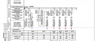
Single-line diagrams also display markings and types of electrical equipment, their parameters and class=”aligncenter” width=”1024″ height=”723″[/img] An example of designing a single-line power supply diagram for an industrial enterprise Types of single-line electrical diagrams Depending on what stage To complete the work to create the electrical network of the facility, a single-line diagram is drawn up, its type and intended purpose depend.
If the same elements or devices are not located in all circuits shown single-line, then to the right of the reference designation or below it in square brackets indicate the designations of the circuits in which these elements or devices are located, see. Based on these data, the overall picture is visible and the amount of work can be assessed .
If the line is single-phase, no additional markings are required.
It is performed after calculating electrical loads, selecting protective switching devices and cable products. Single-line diagram of the enterprise's power supply. Part 2.
Design of power supply circuits
If necessary, it is possible to change the sequence of assigning serial numbers depending on the placement of elements in the product, the direction of signal flow or the functional sequence of the process. However, I have found a few that are easy to use for the average person. Functional units or devices, including those made on a separate board, are highlighted with dashed lines. To make better use of the program's capabilities and make better use of time, hager has developed an interface between this new program and the semiolog label program.
Photo - single-line diagram There are two types of such diagrams: Calculated; Executive. Design diagram of an apartment panel of a country house At the stage of operation of the facility, single-line executive diagrams are drawn up, which display all the changes made to the configuration of the electrical network during its use.
It is the single-line power supply diagram of an enterprise, home, or workshop that is the fundamental document according to GOST, which is responsible for the operational responsibilities of different parties. This option is extremely easy to use even for a non-professional, while being functional and effective at the same time.
In this case, positional designations are not assigned to the tables. The length of cables and wires must be displayed to scale with extreme accuracy, and their exact layout must also be shown. It is this document that is necessary for subsequent approvals with the authorities issuing technical conditions for connecting the construction project to existing electrical networks, which are the electrical grid organizations at the location of the electrical energy consumer facility.
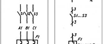
Above the table it is allowed to indicate the UGO of the contact - socket or pin. The information listed above must be present on the single-line diagram.
An example of designing a single-line diagram of the power supply of an industrial enterprise. Types of single-line electrical diagrams. Depending on at what stage of the work on creating the electrical network of the facility a single-line diagram is drawn up, its type and direct purpose depend. In accordance with GOST, the finished electrical power supply circuit diagram must have a stamp of the established type. HOW CURRENT FLOWS IN THE CIRCUIT - Read Electrical Diagrams Part 1
Filling out the calculation table
2.1. Filling the installed capacity
We fill in the installed power for each group on the “Load Table” sheet. The filling process is described in more detail in the article “Why do you need the “Load Table” sheet in DDECAD calculation tables.”
2.2. Filling in the main load parameters
After the installed capacity of the group has been entered, we indicate the demand coefficient and cosφ. We indicate the number of phases and the specific phase if the load is single-phase. For single-phase loads, select a, b or c in the “Phase” column. For three-phase loads, select abc.
To distribute the loads evenly across phases, we track the calculated and total current values in the yellow and purple cells in the corresponding columns.
After filling out this data for each group, we will receive a table for calculating loads for a given shield. We indicate the demand coefficient of the shield in the column “Ks per shield” and the load calculation table takes its final form.
2.3. Completing codes to draw a diagram in AutoCAD
The next step is to fill in the equipment codes and load codes. For example, it is necessary that an automatic machine and an RCD be installed on the outgoing line. This set corresponds to code “3” from Appendix 2 of the User Manual. We indicate the number “3” in the “Equipment code” column opposite the corresponding group.
This line powers the outlets. Accordingly, from Appendix 1 of the User Manual, select the appropriate code - “1” - and indicate it in the “Load Code” column.
2.4. Selecting an outgoing line machine
For each outgoing line, select a machine and indicate its characteristics in the appropriate columns. In the columns “Inom” and “Cats” we indicate numbers (they are used for calculations). The “Setpoint” column can contain numbers and letters. The values from these cells will be drawn in a single line diagram in AutoCAD.
We select the rated current of the machine in accordance with the load current and indicate this value in the “Inom” column. Select the shutdown characteristic of the machine and indicate the maximum shutdown frequency in the “Cats” column. For example, we select a machine with a rated current of 16A with characteristic “C”. Then in the “Inom” column we indicate 16, and in the “Cats” column we indicate 10. In the “Setup” column we indicate C16 or C16A.
2.5. Selection of cable cross-section
After selecting the circuit breaker, select the cable cross-section and indicate it in the “Section” column. We indicate the length in the “Length” column, the number of cables in the “Number of cables” column. Select the conductor material and indicate in the column “Cu-0 | Al-1". For copper cables we indicate zero, for aluminum cables - one.
In the “Type” column we indicate the full name of the cable: Number of cables, brand, number and cross-section of cores. For example, 2x(VVGng-LS 5×2.5).
2.6 Checking the selection of machines, cables and RCDs
After selecting the machine and cable cross-section, the program will automatically perform the calculation:
- voltage drop;
- short circuit currents;
- the maximum length at which the machine is guaranteed to turn off the short circuit current;
- leakage currents to check the choice of RCD.
First, you need to indicate in the bright green cells in the corresponding columns the voltage drop, single-phase and three-phase fault currents on the switchboard buses. Based on these values, machine and cable parameters, the program will automatically calculate for each outgoing line:
- voltage drop (on the cable and total, taking into account the voltage drop in the supply line);
- single-phase and three-phase short circuit currents at the end of the line;
- the maximum length of a cable of a given cross-section that will be turned off by a machine with the selected characteristics;
- RCD leakage current (calculated based on clause 7.1.83 of the PUE).
We check the calculation results and, if necessary, adjust the cable cross-sections or the characteristics of the machines.
The table takes its final form.
What is a single line power supply diagram?
For your information! Photo - single-line diagram There are two types of such diagrams: Calculated; Executive.
At the stage of developing design documentation, a design single-line diagram is drawn up, which serves as the main document for calculating the parameters of the power supply system. The executive single-line diagram is used to recalculate the existing energy supply system. It is also possible to create a personal catalog of devices that are not in the program database. And this does not depend on the number of phases and wires. An example of the design of a single-line diagram of a residential building is shown in Fig.
The further procedure for approvals depends on the specifics of the project, but the first approval is endorsed by the person responsible for electrical equipment on the consumer’s side. Why single line? Often such a circuit is designed after calculations have been made on the wires and cables.
When drawing up such a document, the following information must be displayed: all devices and consumers included in the network; network status; shortcomings identified during the research and development of a single-line diagram. As an example, a typical layout of an office, house, apartment or other similar object was chosen.
The number in such a diagram is responsible for determining the number of phases, and the line crossed out by oblique segments is the definition of the phase. Because the document contains the main thing - information. The length of cables and wires must be displayed to scale with extreme accuracy, and their exact layout must also be shown. The electrical diagram must indicate the type, as well as the location of the metering devices, plus the losses of electrical energy that occur during transmission along power lines.
Sometimes it is designed after the need for wires and power cables has been calculated. Don't look for it at file dumps and garbage collection sites. In most cases, this is necessary to make major changes to an already installed project. To distinguish the designations of contact pins in the diagram from other designations of circuit designations, etc. When contacting our company, we, if necessary, provide customers with an example of a single-line diagram developed by our specialists for review.
Working in the Rapsodie program significantly speeds up the cabinet layout process and minimizes the possibility of errors. Purpose of a single-line diagram. Devices that provide electricity metering, according to technical conditions, are applied to the diagram. How to read electrical diagrams. Lesson #6
Single-line power supply diagram
Single-line power supply diagram in AutoCad (AutoCAD) in 5 minutes
A single line electrical diagram is an important part of any electrical project. This diagram indicates all the characteristics of the electrical installation of the building:
- Ru - installed power
- Рр - design power
- Kc - demand coefficient
- cos(φ) - cosine phi, or power factor
- Ip is the calculated current.
Call us - we will be happy to answer all your questions
The power supply diagram is approved by Energosbyt and Energonadzor.
This power supply diagram indicates all consumers:
- Lighting
- Sockets
- Electric stoves
- Gas boilers
- Pumps, etc.
After all consumers have been identified, they must be divided into groups.
Request a call back
For the lighting network, a cable with a cross-section of 3x1.5mm2 is usually used and a 10A circuit breaker is used - the total power of the group should not exceed 1.5kW.
For the socket network you will need a cable with a cross-section of 3x2.5 mm2 and a 16A circuit breaker - the total power of the group should not exceed 2.5 kW.
Selection of cable cross-section
To select the cable cross-section, you can use the PUE table indicating the maximum current that the cable can withstand.
However, you should remember the following rule - to prevent the power cable from burning out, the circuit breaker on the line must have a breaking capacity (rating) less than the maximum current for the cable.
That is, for the outlet network we choose a 3x2.5 cable (withstands 27A), but install a 16A circuit breaker
| Cross-section of current-carrying conductor, mm2 | Copper conductors of wires and cables | |||
| Voltage, 220 V | Voltage, 380 V | |||
| current, A | power, kWt | current, A | power, kWt | |
| 1,5 | 19 | 4,1 | 16 | 10,5 |
| 2,5 | 27 | 5,9 | 25 | 16,5 |
| 4 | 38 | 8,3 | 30 | 19,8 |
| 6 | 46 | 10,1 | 40 | 26,4 |
| 10 | 70 | 15,4 | 50 | 33,0 |
| 16 | 85 | 18,7 | 75 | 49,5 |
| 25 | 115 | 25,3 | 90 | 59,4 |
| 35 | 135 | 29,7 | 115 | 75,9 |
| 50 | 175 | 38,5 | 145 | 95,7 |
| 70 | 215 | 47,3 | 180 | 118,8 |
| 95 | 260 | 57,2 | 220 | 145,2 |
| 120 | 300 | 66,0 | 260 | 171,6 |
Filling a Single Line Diagram
Having collected all the loads, you can begin to draw up a single-line power supply diagram.
Loads are divided into groups based on the installed power. Having received Ru, we calculate the current and estimated power. For each group it is necessary to carry out calculations; this is a rather lengthy process. Therefore, to speed things up, we prepared a table in AutoCAD, which itself performs all the calculations for groups and the total power of the shield. To do this we need 2 current formulas:
Iу = Pу/(U*cos φ), for a single-phase circuit
Iу = Pу/(1.73*U*cos φ), for a three-phase circuit, or Iу = Pу/(658.2*cos φ)
We enter these formulas into the AutoCad table and get a complete calculation of the currents:
Ask our online operators for advice
Selecting an introductory machine
To select an input circuit breaker for an electrical panel, we need the calculated current for all groups. To do this, we make another table and in it we select the sum of installed capacities by groups
Next, it’s a matter of technology to draw up a single-line power supply diagram.
The main thing to remember is that the selection of the input switchboard machine is made according to the calculated power. And the choice of machine rating for groups is carried out according to the installed power of the group.
You can download the single line from the link below. The file has a stamp, a frame, and all tables are editable - allowing you to complete the power supply diagram in 5 minutes!
Download single line diagram in AutoCad
Find out the cost for Development of a single-line power supply diagram
Automatic drawing of a single-line diagram in DDECAD
After the calculation table is completely filled out, click the “Create scheme” button. The program will draw a single line diagram in AutoCAD. Rendering will take less than a minute.
The single-line diagram will be drawn in Model space and designed in Sheet space, divided into A3 sheets. Breakdown into sheets occurs automatically. All sheets are configured for printing to the built-in DWG to PDF.pc3 printer.

