General provisions
In high-volume manufacturing, each part is manufactured to a predetermined degree of precision. It is almost impossible to make them with completely identical characteristics. Therefore, a harmonious system of permitted changes in real accuracy classes is provided.
In metalworking technology, tolerance is the value established by the standard by which it is allowed to change the processing accuracy.
Each parameter is indicated on the drawing. The specified tolerance size reflects the numerical characteristics of the permitted gap and its location on the product. According to the rules, the placement of the area to which the tolerance relates is oriented relative to the so-called zero line. For this indicator, tolerances are:
- symmetrical and asymmetrical (allowed deviation is allowed on one or both sides relative to the selected zero line);
- above or below a given normal;
- with a given amount of displacement in the required direction.
Fit is a parameter that indicates the acceptable accuracy when connecting individual parts into a single unit. It is set by the established gaps or interference.
They are divided into three approved types:
- a predetermined gap;
- permissible interference;
- transitional type.
In all cases, the fit tolerance is considered to be the value that is calculated as the difference between the largest and smallest value of the permissible gap. The entire existing system is classified according to the following criteria:
- the bases of the system are the tolerances of holes and shafts;
- accuracy classes (they are divided into 19 qualifications);
- the magnitude of the prescribed interference.
Tolerances for holes are understood as a set of permitted values with the same qualifications. For them, maximum permissible hole sizes are established. Variation in the size of the landings is achieved by changing the maximum dimensions of the shaft. In the shaft system, the listed parameters change in the reverse order. The maximum shaft size remains constant for different fits, but the maximum hole dimensions change.
In the system of tolerances and landings, qualification numbers are indicators of processing accuracy. As the serial number increases, the size tolerance increases. All sizes are divided into a certain number of intervals. The size of each interval is three millimeters. The ruler of these intervals starts with a size from 1 to 3 mm, then from 3 to 6 mm and so on. Each interval has its own average geometric size and designation. It is determined by the boundaries of the interval. Qualifications from fifth to seventeenth are defined for them. The lower the quality number, the more accurate the processing is.
All calculated parameters are summarized in tables. The main documents that systematize these indicators and the rules for their designation are:
- ESDP stands for a unified system of admissions and landings - established by GOST 25347-82;
- NDCs are enshrined in standard 25346-89 (the basic standards of interchangeability establish the possibility of replacing some products with similar ones);
- ESKD unified system of design documentation combines all requirements for the design of documents and markings - it is set out in detail in standard 2.001-2013;
- Standards of various levels and purposes: government departmental, industry;
- Technical specifications (used as standards for the manufacture of highly specialized parts).
Download GOST 25346-89
Download GOST 25347-82
Download GOST 2.001-2013
ESDP is used to regulate all parameters. ONV allows you to accurately determine gaps in parts of complex configurations. For example, keyed or splined connections, threads, gears, and so on.
Each size must be indicated in each of the documentation:
- on all types of drawings;
- design sketches;
- technological maps;
- additional graphic images (explanatory notes, sketches).
Correctly selected deviation parameters form the basis of technological processes. Constant adherence to approved standards allows us to develop and manufacture a reliable and durable unit.
Designations on mechanical engineering drawings
A drawing of a product is a graphic representation of it, made to a certain scale, indicating the dimensions and conventionally expressed technical conditions, compliance with which must be ensured during the manufacture of the product. Drawings are carried out according to the uniform rules established in GOST standards of the Unified System of Design Documentation (ESKD).
Designation of materials in sections. Table I.5 shows a graphic designation of materials most common in mechanical engineering
Designation of dimensions of product surfaces. Table I.6 gives designations on mechanical engineering drawings . Dimensions must be accompanied by permissible maximum deviations from nominal values. Maximum deviations can be indicated by numbers 18+0.015; 12-0.032-0.059 or symbols for the location of tolerance fields - in upper and lowercase letters of the Latin alphabet, for example 18Н7, 12е8, where the numbers on the right are quality.
Designations of tolerances of shape and location of surfaces. They are indicated on the drawings by symbols in accordance with GOST 2.308-79 (ST SEV 368-76), placed in rectangular frames, divided into parts. In the first blank there is a sign of the type of tolerance; in the second - the numerical value of the tolerance (mm), and in the third - the letter designation of the surface to which the tolerance is associated and which is the base. Examples of indicating tolerances on the shape and location of surfaces in drawings are given in Table. 1.7.
Symbols on sketches of technological documentation. Technological documentation is presented in a unified ESTD system (GOST 3.1105-74 and GOST 3.1404-74). The documents of the unified system include technological sketches, which use a number of symbols for installing and securing workpieces on stacks (Table 1.8). The conditions for installing and securing workpieces must be strictly followed to ensure that products are manufactured within permissible deviations.
Sketches are made subject to the following conditions:
- the workpiece is depicted in the position in which it is processed;
- the surfaces to be treated are indicated by lines whose thickness is at least twice as thick as the other lines;
- the sketch indicates already processed surfaces that must be processed in this operation;
- the surfaces processed in this operation have dimensions, tolerances and roughness marks indicated on the sketch, which must be ensured;
- the movement of the workpiece and tool is indicated by arrows.
Table I.5 Graphic designation of materials in drawings
| Material | Designation |
| Metals and hard alloys | |
| Non-metallic materials chipboard * (excluding wood and plywood) | |
| Abrasives, ceramics, solutions, etc. | |
| Wood | |
| * Particle boards |
Table I.6. Size designations
| Nature of size | Sketch |
| Linear dimensions and correct deviations, expressed in millimeters, are indicated without a unit of measurement. Other units of measurement should be placed next to the number | |
| The values of the diametrical dimensions of cylindrical surfaces are preceded by a diameter sign | |
| The dimension line is parallel to the direction in which the size of the area designated by it is plotted, and the extension lines are perpendicular to it. Angular deviations are indicated with units of measurement | |
| The radius value is preceded by the letter R; its sign is placed above the size of the arc. Dimensions of relatively low accuracy (grades 14, 15, 16, 17) can be indicated without maximum deviations. The accuracy of their implementation is specified in the general technical specifications for the product | |
| With different roughnesses of the same surface, such areas are delimited by a solid thin line. The sizes of the plots are indicated | |
| The dimensions of cylindrical threads contain instructions next to them: what kind of thread it is - in Russian letters, pitch, degree of accuracy and main deviation - in Latin letters |
Table I.7. Designations on the drawings for tolerances of shape and location of surfaces
| Type of admission | Sketch | Content |
| Straightness tolerance | Surface straightness tolerance 0.25 mm over the entire length and 0.1 mm over a length of 100 mm | |
| Tolerance for surface straightness in the transverse direction 0.05 mm, in the longitudinal direction NII 0.1 mm | ||
| Flatness tolerance | Surface flatness tolerance 0.1 mm over an area of 100x100 mm | |
| Flatness tolerance of each surface 0.01mm | ||
| Roundness tolerance | The shaft roundness tolerance is 0.02 (the hole roundness tolerance is also indicated) | |
| Parallel tolerance | Tolerance of parallelism of the surface relative to surface A 0.02 mm | |
| Tolerance for parallelism of the hole axis relative to the base 0.05 mm | ||
| Perpendicularity tolerance | Tolerance of surface perpendicularity relative to surface A 0.02 mm | |
| Tilt tolerance | Tolerance for surface inclination relative to surface A 0.08 mm | |
| Symmetry tolerance | Groove symmetry tolerance T 0.05 mm. Base - plane of symmetry of surfaces A | |
| Alignment tolerance | Alignment tolerance of two holes 0.08 mm | |
| Axis intersection tolerance | Tolerance for intersection of hole axes 7 0.06 mm | |
| Shape tolerance of a given profile | Tolerance of the given profile shape 7 0.04 mm | |
| Total parallelism and flatness tolerance | Total tolerance for parallelism and flatness of the surface relative to the base 0.05 mm |
Note. Before the numerical values of the tolerance within the framework, the following should be indicated: with the symbol Ø, if a circular or cylindrical tolerance field is indicated by its diameter; symbol R if a circular or cylindrical tolerance field is indicated by a radius; symbol T, if the tolerances for symmetry, intersection of axes, the shape of a given profile and a given surface, as well as positional tolerances are indicated in diametrical terms.
Table I.8 Symbols of bases, installation elements and fastening of workpieces
| Installation and fastening method | Designations |
| At smooth centers | |
| On three rigid supports and one self-aligning | |
| In two-, three-jaw self-centering chucks | |
| On a magnetic or electromagnetic plate | |
| On three supports (adjustable) according to the marking line | |
| In a machine vice |
* Number 3 is the number of cams. ** Number 3 is the number of supports on which the workpiece is installed.
Shape tolerances
This type of permitted deviation is caused by processing inaccuracies that occur due to the actual capabilities of the processing equipment.
These include:
- straightforwardness;
- planes;
- mismatch of the circle shape (these include: roundness; ovality tolerance);
- change in the shape of a cylinder - cylindricity tolerance.
The first category includes the following deviations:
- the shape of the processed surface (the planar pattern is disrupted, the radius of the machined shaft changes, the geometry of figures with flat edges is disrupted);
- the parallelism and perpendicular arrangement of surfaces between each other or adjacent parts is disrupted;
- different roughness appears along the length, cross-section, and circumference.
The parameter values are assessed by comparing the nominal surface (indicated in the drawing) and the real one (obtained on machines of a given accuracy class). The resulting deviations allow us to calculate the required tolerance.
A change in the radius of the finished product relative to that specified in the drawing is called a violation of roundness. To prevent possible negative consequences during operation, a roundness tolerance is introduced. When examining a part in one of the planes, the required tolerance of the longitudinal section profile is determined.
The nature of the mutual curvature of the arrangement of planes is divided into the following types:
- general parallelism (compared to a line directed along the surface);
- perpendicularity and intersection of axes (the preservation of a right angle throughout the entire surface is checked);
- tilt;
- symmetry (relative to the selected axis).
The flatness tolerance determines the amount of permitted deviation from the designated level. The main characteristic is the so-called tolerance zone. It is designated in a selected area, which is located between planes for which strict parallelism parameters must be observed. The distance to the surface is determined by existing standards. Monitoring the deviation of these parameters from those specified in the drawing is indicated on the profilogram.
9.9. Making a gear drawing
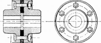
A gear is an important component of many designs of devices and mechanisms designed to transmit or transform motion. The main elements of a gear wheel: hub, disk, ring gear (Figure 9.16).
Figure 9.16 — Elements of a gear wheel The tooth profiles are normalized by the relevant standards. The main parameters of the gear are (Figure 9.17): m=P t
/ ?
[ mm
] – module;
d a
=
m st
(
Z
+2) – diameter of the circle of the tops of the teeth;
d
=
m st Z
– pitch diameter;
d f
=
m st
(
Z
– 2.5) – diameter of the circle of the depressions;
S t
= 0.5 m
st
? – tooth width; ha – height of the tooth head; hf – height of the tooth stem; h = ha+hf – tooth height; Pt – dividing circumferential step.
Figure 9.17 - Gear parameters The main characteristic of the ring gear is the modulus - a coefficient connecting the circumferential pitch with the number ?.
The module is standardized (GOST 9563-80). m = Pt / ? [mm] Table 9.1 - Basic norms of interchangeability. Gear wheels. Modules, mm
| 0,25 | (0,7) | (1,75) | 3 | (5,5) | 10 | (18) | 32 |
| 0,3 | 0,8; (0,9) | 2 | (3,5) | 6 | (11) | 20 | (36) |
| 0,4 | 1; (1,125) | (2,25) | 4 | (7) | 12 | (22) | 40 |
| 0,5 | 1,25 | 2,5 | (4,5) | 8 | (14) | 25 | (45) |
| 0,6 | 1,5 | (2,75) | 5 | (9) | 16 | (28) | 50 |
On educational drawings of gears: Height of the tooth head – ha = m; Height of the tooth stem – hf = 1.25m; Roughness of tooth working surfaces – Ra 0.8 [µm]; At the top right of the sheet, a table of parameters is drawn up, the dimensions of which are shown in Figure 9.18; often only the modulus value, the number of teeth and the pitch diameter are filled in.
Figure 9.18 — Table of parameters Wheel teeth are shown conventionally, according to GOST 2.402-68 (Figure 9.19). The dashed line is the dividing circle of the wheel. In the section the tooth is shown uncut.
| A | b | V |
Figure 9.19 - Image of a gear wheel a - in section, b - in front view and c - in left view. The roughness on the lateral working surface of the tooth in the drawing is marked on the pitch circle. An example of a gear drawing is shown in Figure 9.20.
Figure 9.20 — An example of a training drawing of a gear
Location tolerances
This category of characteristics combines the allowed intervals for changing the following geometric parameters:
- perpendicularity (angular characteristics between planes must be strictly observed);
- parallelism (the distance between individual elements is maintained within the limits of permitted changes throughout the entire surface);
- alignment;
- tilt;
- symmetry;
- axis intersections.
In addition to the listed parameters, this category includes the so-called positional tolerance. It is installed for parts that have several holes, from which the unit will later be assembled. The positional tolerance dimensions are reflected between the centering holes. It is indicated by a special sign in the form of a circle, which is intersected by a small segment. It can be positioned horizontally or vertically.
In modern parts there are a large number of options for deviations from parallelism. These can be deviations of parallelism between planes, individual surfaces or an entire group between holes. The parallelism tolerance is assessed using a special database. Tolerance signs for the arrangement of elements for which it is necessary to check parallelism are a set of special graphic images. Checking parallelism allows you to determine the angle of deviation of one plane from another.
What do horizontal (Japanese) symbolic emoticons mean?
Initially, it so happened that most of the text emoticons that were invented and became widespread had to be deciphered as if “tilting the head to the side.” However, this is not entirely convenient, you will agree. Therefore, over time, their analogues began to appear (also typed from symbols), which did not require virtually or actually tilting the head to the side, because the image created by the symbols was located horizontally.
Let's look at what the most common horizontal text emoticons mean
:
- (joy) is usually indicated: (^_^) or (^____^) or (n_n) or (^ ^) or \(^_^)/
- in symbols they are designated as: (<_>) or (v_v)</_>
- The following symbols mean different things: (o_o) or (0_0) or (O_o) or (o_O) or (V_v) (unpleasant surprise) or (@) (meaning “You can be stunned”)
- Emoticon meaning: (*_*) or (*o*) or (*O*)
- I'm sick: (-_-;) or (-_-;)~
- Sleeping: (- . -) Zzz. or (-_-) Zzz. or (u_u)
- Confusion: ^_^" or *^_^* or (-_-«) or (-_-v)
- Anger and rage: (-_-#) or (-_-¤) or (-_-+) or (>__
- What does fatigue mean: (>_
- Jealousy: 8 (>_
- Distrust: (>>) or (>_>) or (<_>
- Indifference: -__- or =__=
- This emoticon text expression means: (?_?) or ^o^;>
- Value close to: (;_;) or (T_T) or (TT.TT) or (ToT) or Q__Q
- What does winking mean: (^_~) or (^_-)
- Kiss: ^}{^ either (^}...{^) or (^)(^^)
- High five (means friend): =X= or (^_^)(^_^)
- Carrot Love: (^3^) or (*^) 3 (*^^*)
- Apology: m (._.) m
- Greedy emoticon: ($_$)
</_>
Naturally, on many blogs and forums it has long been possible to add emoticons in the form of pictures (from ready-made sets), but many still continue to use text emoticons, because they have already gotten their hands on this and there is no need to find the right one in the catalog picture.
If you want to know what this or that set of characters that is a text emoticon means, write about it in the comments. Maybe the whole world will figure it out...
Good luck to you! See you soon on the pages of the blog site
You might be interested
Emoticons on Twitter - how they are inserted and where you can copy pictures of emoticons for Twitter LOL - what is it and what does lOl mean on the Internet File - what is it and how to set up a file in Windows Hidden emoticons in Skype - where to get new and secret emoticons for Skype Impress - what is it (the meaning of the word) What is rofl and roflit, or +1 to understanding youth slang Flex - what does it mean and what is flex Otzovik - a site for reviews about everything and how you can make money on it Dog symbol - why is the dog icon @ so called, the history of the appearance of this sign in the email address and on the keyboard ICQ and its web version - the good old free online messenger with new features
What do tire markings mean?
All possible designations
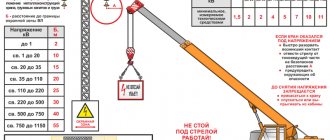
On the sidewall of any tire you can see many different symbols - numbers, letters, icons, etc. Knowing how to decipher these designations, you will receive the most comprehensive information about the tire.
1. This is how the tire size is indicated. The first digit in the index indicates the width of the tire in millimeters, the second - the profile height as a percentage of the width. This is followed by a letter indicating the design of the tire, and a number indicating the tire's seat diameter in inches. For example, the designation 195/65 R15 is deciphered as follows: tire width 195 mm, profile height - 126.75 mm (65% of the width), R - radial tire (there are also diagonal ones, but they are practically not found today), seat diameter for installation on a disk - 15 inches. Sometimes such an index does not indicate the profile height (for example, 195 R15). This means that its value exceeds 80%. Such tires are called full-profile. They are often equipped with light commercial trucks and vans.
2. Index or load factor. It is designated by numbers from 0 to 130, but the most common range is from 71 to 110. Moreover, each combination has its own permissible tire load in kilograms (see table). Sometimes manufacturers indicate its load capacity directly on the tire (in particular, this is mandatory for tires approved for sale in the United States). In this case, on the sidewall you can see the inscription Max Load and the load value in kilograms and British pounds. For example, Max Load 515kg (1135lbs).
71 345 72 355 73 365 74 375 75 387 76 400 77 412 78 425 79 437 80 450 81 462 82 475 83 487 84 500 85 515 86 530 87 545 88 5 60 89 580 90 600 91 615 92 630 93 650 94 670 95 690 96 710 97 730 98 750 99 775 100 800 101 825 102 850 103 875 104 900 105 925 106& nbsp; 950 107 975 108 1000 109 1030 110 1060
3. Speed index.
It is indicated in Latin letters (for decoding, see the table) and indicates the maximum speed the tire is designed to travel at.
Speed index / Speed, km/h / Speed, mph B / 50 / 31 C / 60 / 37 D / 65 / 40 E / 70 / 43 F / 80 / 50 G / 90 / 56 J / 100 / 62 K / 110 / 68 L / 120 / 75 M / 130 / 81 N / 140 / 87 P / 150 / 93 Q / 160 / 100 R / 170 / 106 S / 180 / 113 T / 190 / 118 H / 210 / 130 V / 240 / 150 W / 270 / 168 Y / 300 / 186 ZR / 240+ / 149+
4. This inscription indicates a reinforced tire frame,
which is relevant for commercial vehicle tires. Therefore, often instead of the word Reinforced on the sidewall, the manufacturer simply adds the letter C (which means commercial) to designate the tire parameters. For example, 195/65 R15 C.
5. Country of manufacture of the tire.
For example, made in France - made in France, made in Germany - made in Germany.
6. For tires with an asymmetric tread pattern, the designation of the side external to the body is applied to the sidewall.
It is marked with the word Outwards, Out, Side facing outwards, etc.
7. An indication of the tire’s suitability for various operating conditions:
M+S - Mud + Snow: mud plus snow As - All Season: all-season Aw - Any Weather: Any weather Aquatred, Aquacontact, or umbrella pictogram - special rain tires.
Pictogram in the form of a snowflake - tires for harsh winter conditions. If there are no such markings on the sidewall, then the tire can only be used in summer, in warm weather.
8. Tire design – tubed or tubeless. Designated Tube Type (TT) or Tubeless (TL), respectively.
9. Certification mark. On tires approved in Europe under UNECE Regulation No. 30, it consists of the letter E inscribed in a circle and a numerical index corresponding to the country that issued the approval. For example, Russia is assigned number 22 on this list. This is followed by a long set of numbers - the number of the certificate of compliance with the standards. Tires that meet American standards additionally bear the DOT designation, which encrypts data not only about the test report number, but also about the tire manufacturer. For example, DOT MKR4 AJOR
10. Name or logo of the tire manufacturer. For example, Michelin, Good Year, Yokohama.
11. Tire model. For example, Energy, SP Sport 9000, Turanza ER300.
In addition, on many tires you can find additional designations:
Tire release date. It's a four-digit number like 1109, which is week 11 of 2009 production.
Regrooveable - a tire with the possibility of additional tread depth.
TWI (Tread Wear Indication) - this sign on the sidewall of the tire indicates the placement of a wear indicator on the tread (remember that in Russia its depth must be at least 1.6 mm). Usually this symbol is applied around the circumference in six places. It can be done in different ways. For many manufacturers, the indicator is a simple protrusion in the tread groove. When they are compared in height, the tire must be recycled. In more advanced models, the indicator looks like a set of numbers indicating the remaining tread height. As it wears out, the numbers are gradually erased.
Maximum Pressure - maximum pressure in a cold tire. Usually specified in pounds per square inch (1PSI=0.0069 MPa) or bar units, practically equal to the atmosphere.
An arrow, sometimes labeled Rotation, indicates the required direction of rotation for a tire with a directional tread pattern.
Tread Wear Index - Wear resistance index. A conditional value showing how durable the tire is. For example, a tire with the designation 200 should theoretically have twice as much service life as an analogue with the index 100. But in practice, this is only achievable in ideal conditions of a test site or laboratory, where there is no influence of factors such as the driver’s driving style, road quality, etc. .d.
Traction Index – index of tire grip properties (A – Excellent, B – Average, C – Satisfactory). It is determined during testing at a special test site using a special method. It mainly evaluates braking quality rather than cornering stability.
Temperature Index – temperature index (A – excellent, B – Average, C – Satisfactory). This indicator determines the tire's resistance to high temperatures. The higher the rating, the less the tire changes its properties when heated. Tests are carried out in the laboratory on a special stand.
Colored dots (white, red, yellow) on the sidewall indicate the lightest point of the tire relative to its center of rotation. This is where the valve should be installed. If there are both yellow (white) and red marks on the tire, then the latter is located in the heaviest place of the tire.
Also, the tire sometimes contains symbols indicating its special properties. In particular, RunFlat tires (RSC - RunFlat System Component) allow you to move for some time on a punctured wheel. In addition, there are models that provide rim protection. As a rule, such tires are used by automakers of premium segment cars.
- An example of different orientation is also the designation of time.
- Therefore, a special term is required to refer to it.
- The green Martians do not have a word corresponding in meaning to this earthly designation.
- Each badge has a ribbon designating the position of its owner or the sport for the participants.
- Information about the conventional digital designation of the type of transaction is also entered into the personal account.
- For a chess player, it means a strong move.
- The symbols are the same as in Fig.
- Each shard with a layer designation was given to specialists.
- In this case, the designation of a certain type of society may coincide with the name of a given system of sociologists.
- The designations of witchcraft itself are also associated with the verbs of speech: Russian.
- On the inner surface of the roll you need to pay attention to the letter and number designation.
- There are many names for this idea.
- Key words for new paths: atonal music and dodecaphony.
- The center marker looks like a cross to indicate the center of a circle or arc.
- At the same time, the same term is used to designate a certain type of objects of law.
- Means of denoting the actions and qualities of the proponent are verbs of speech and thinking.
- Circles can be used to indicate subordinate clauses instead of rectangles.
- In mathematics, it is customary to use Latin, rather than Russian, letters to denote points and lines.
- And to avoid confusion, different terms are needed to designate these two types of social reality.
- Now the need to introduce negative numbers to indicate the brightness of stars will become clear.
The section is very easy to use. Just enter the desired word in the field provided, and we will give you a list of its meanings. I would like to note that our site provides data from various sources - encyclopedic, explanatory, word-formation dictionaries. Here you can also see examples of the use of the word you entered.
designation in the crossword dictionary
Explanatory dictionary of the Russian language. D.N. Ushakov
designation
designations, cf. (book).
- only units Action according to verb. designate-designate. Marking paths with dotted lines.
A sign by means of which something. designated, designated. Symbols (on geographical maps, etc.).
Explanatory dictionary of the Russian language. S.I.Ozhegov, N.Yu.Shvedova.
New explanatory dictionary of the Russian language, T. F. Efremova.
Total tolerances of shape and location
Each of these parameters combines both permissible deviations. They arise as a result of the simultaneous manifestation of a change in geometric shape and the appearance of unevenness (roughness) of the treated surface. Therefore, using mathematical terminology, they say that the limit to which the difference between the standard and the real product should tend is considered the total tolerance of shape and location. The nature of the changes is determined by the method of comparison with the selected base objects. As such objects, proven structures or surfaces are chosen that can be considered standards, for example, various calibers.
Such tolerances are divided into the following categories:
- Beating. These include: radial, end, in a predetermined direction;
- All surface shapes.
Each of these categories has its own designation. The total runout tolerance is indicated by two oblique arrows in the form of vectors combined from below, directed from the lower left corner to the upper right. Comparison of shapes is made by combining both surfaces.
The field of this parameter is a limited area of space in which all points belonging to the surface must be located.
This field has specified geometric dimensions. It is oriented relative to the selected base so that the parallelism of the location can be checked. Examples of total tolerance indicate how much it is possible to change parameters without leading to rapid failure of the unit. This is especially true for mobile connections
Unification and standardization
To make it easier to read drawings in the production process, there are special GOSTs (state standards). They are combined into a set of rules, which is referred to as a UNIFIED SYSTEM OF DESIGN DOCUMENTATION (USD).
GOST 2.321−84 establishes letter designations that are commonly used in design documents and assembly drawings used in various industrial sectors. The dimensions of products or parts and total dimensions are indicated in capital letters.
When designating different quantities in one drawing with the same letter, the use of indices or their combinations is allowed. Example designation: R, R1, R2, Dn, Dn1, Dn2.