The transmission of electrical energy over any distance is carried out through metal conductors, which must be separated by a dielectric. Not only the efficiency of the power system, but also human safety largely depends on the quality of insulation. However, over time, the technical characteristics of the dielectric are lost, which is why the dielectric strength of the insulation in all devices must be periodically checked.
Electrical aging can be accelerated due to the influence of a number of factors. To understand them, we will take a more detailed look at the structure and physical processes occurring in dielectric materials.
What is electrical strength?
Electrical strength for any insulation should be understood as the minimum potential difference applied per unit thickness at which discharges begin to occur. Electric strength is a nonlinear function, the change of which depends on the following factors:
- Insulation thickness;
- Dielectric constant;
- Temperatures of both the surrounding space and the insulation itself;
- Type of dielectric;
- Type of applied voltage (AC or DC).
Thus, we can say that the insulation strength determines the breakdown voltage. In practice, for each material this parameter is calculated empirically after numerous tests.
Rice. 1. Effect of voltage on a dielectric
The value is measured as V/mm or kV/cm, etc., for example, dry air, on average, has a strength of 32 kV/cm.
However, the strength of the insulation will also depend on the aggregate state of the material:
- Solid dielectrics - the most common in cable and wire products, are intended for the manufacture of insulation of cores, device housings, gaskets, etc. After a breakdown or micro-breakdown, the insulation is destroyed, channels are formed through which a repeated breakdown will occur at a lower voltage.
- Liquid dielectrics - the most common option is transformer oil, used in transformers, switches, and high voltage cables. Due to their movable structure, they have the ability to recover, which makes them excellent in oil circuit breakers, where the insulation simultaneously extinguishes the arc and is then restored.
- Gaseous insulation - air is used around the windings of a transformer or other electrical apparatus, the same can be said for some types of high-voltage circuit breakers. But modern devices often use SF6 gas or nitrogen. Gases are also easily restored after a breakdown.
Physically, the electrical strength of dielectrics is ensured due to the absence of free charge carriers in the material. Dielectric molecules hold electrons so firmly in their outer orbits that even applied voltage cannot remove them from their orbits. Of course, if we consider the ideal option - the arrangement of the material between two plates to which voltage is applied, then it will not flow through it. However, all atoms will receive additional energy, which will create a greater electric field strength, both in the entire solid insulation and in each individual atom.
But, if between the above plates you place not one piece of dielectric, but two from different materials, or half from air and the other from plastic, then the electric field strength in these materials will differ due to the fact that they have different dielectric constants. This is one of the most important factors in reducing electrical strength.
Topic 2. Electrical tests
Electrical tests of devices and systems are carried out to check the electrical strength, insulation resistance and normal functioning of the aircraft. Electrical tests include: autonomous tests of devices, assemblies and systems before installation on the device, tests during the assembly process; comprehensive testing of undocked and docked aircraft. Electrical strength and insulation resistance are checked on assembled blocks or systems:
— between electrical circuits and metal insulated parts of devices;
— between electrical circuits that are disconnected during operation;
- between electrically unconnected circuits.
First, the electrical strength is checked, and then the electrical insulation resistance is measured. The scope of electrical tests is determined by the NTD.
2.1. Electrical strength test
Electrical strength is the ability of electrical insulation to withstand the action of electrical voltage applied to it. It is determined by the voltage value at which breakdown occurs - breakdown voltage.
Electrical strength can be determined using the formula
where is the field inhomogeneity coefficient; - voltage causing breakdown; — insulation thickness.
Breakdown voltage depends on surface roughness, presence of oil, moisture, dust, hygroscopicity, etc. The rated voltage applied to the product insulation during normal operation is less than the breakdown voltage. The test voltage for checking the electrical strength of insulation depends on the rated voltage, its power, operating modes and is determined by the normative and technical documentation.
During testing, it is allowed to combine several electrically independent circuits having the same operating voltage into a single system.
The test voltage is calculated using the formula
where is the voltage determined by the technical documentation; - coefficient; - Rated voltage. The test voltage must be sinusoidal. In practice, the insulation is subjected to a maximum voltage with an amplitude of .
With a peak voltage at the same effective value, the amplitude is much greater.
The test voltage should increase and decrease smoothly. When the voltage is suddenly turned on or off in the circuit under study, which has significant inductance, shock overvoltages may occur; the shock field strength at the moment of the pulse will be greater than the electrical strength of the insulation, and then a breakdown will occur. The duration of the test voltage change to must be more than 10 s. It is possible to change the voltage in steps from 0 to 0.5, then in steps of (0.05 - 0.10) increase to the maximum voltage, hold for 1 minute and step down the voltage.
Installations for testing electrical insulation strength usually have a power of more than 500VA, so only specialists who have undergone special safety training are allowed to operate.
The insulation of aircraft having different conductivities in different directions is subjected to direct current voltage testing.
The electrical strength of the interturn insulation of the windings of electrical machines is checked at idle by gradually increasing the voltage on the winding. The insulation must withstand a voltage of 1.5-2 times the operating voltage for 5 minutes. The breakdown of the interturn winding insulation is monitored by reducing the voltage.
When checking the electrical strength of products under reduced pressure conditions, tests are carried out in a pressure chamber at test pressure.
2.2. Insulation resistance test
Under the influence of applied voltage, electrical insulating materials exhibit electrical conductivity. The electrical conductivity of dielectrics is much lower than that of conductors, and at the same time this characteristic of dielectrics plays an important role in the functioning of equipment. The leakage current of a dielectric has two components: the current passing along its surface and the current passing through the dielectrics. The ratio of the voltage applied to the dielectric to the leakage current is called the insulation resistance. Insulation resistance can be determined by the relation
where is the leakage current along the insulation surface; — leakage current through the insulation layer.
Insulation resistance depends on mechanical influences, temperature, penetrating radiation, state of the dielectric surface, quality of processing, assembly, impregnation, etc.
Insulation resistance is checked, as a rule, in normal climatic conditions after exposure to mechanical and climatic factors.
The lower limit of the insulation resistance should be:
— in a cold dry state ≥20 Mohm;
— in a heated state ≥2 Mohm;
— in a humidified state, at least 1 Mohm;
In some cases, a lower insulation resistance limit may be set.
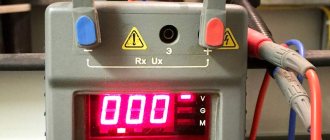
Insulation resistance is checked in the following ways:
— network and manual megaohmmeters,
- using a voltmeter with a certain internal resistance.
The insulation resistance of the input of the measuring instruments must exceed the measured insulation resistance by an order of magnitude. The measuring voltage must match the operating voltage of the circuit being measured. Registration of insulation resistance values is carried out, as a rule, one minute after applying the measuring voltage.
To measure insulation resistance, magnetoelectric megohmmeters and megohmmeters using electronic autocompensation circuits are most often used.
Reasons for the decrease in electrical strength
The strongest influence on the state of insulation is exerted by the supply of alternating voltage and temperature jumps to maximum standards and above. Temperature fluctuations accelerate the movement of atomic particles, which increases the conductivity of the insulation and, accordingly, reduces its electrical strength. Lowering the temperature has the opposite effect - it takes more energy for the atoms to free up electrons or ions within the thickness of the dielectric.
The alternating voltage creates polarization of particles, which change their direction to the opposite direction 100 times per second. For materials with a high degree of purity, this factor does not pose a great threat, but all inclusions of foreign substances behave differently. Due to the inhomogeneity of the field, during the transition from isolation to inclusion, a change in the physical parameters of electrical quantities occurs. Over time, inclusions expand and reach the size of microcracks, which leads to aging of the insulation.
The end result of reduced insulation strength is electrical breakdown, which can lead to dielectric failure and failure of the associated equipment.
By type they are divided into:
- Electrical - occurs in solid insulating materials, characterized by an avalanche-like process in which natural bonds within the atom are broken;
- Thermal breakdown occurs when the insulation receives more thermal energy than it can remove. It occurs as a consequence of softening, which leads to deformation and a decrease in the thickness of the material;
- Electromechanical – typical for fragile insulation (porcelain, ceramics) where internal discharges lead to mechanical damage;
- Electrochemical – caused by a change in the chemical composition of the insulation. Most often, as a result of aging, sometimes due to the diffusion of the conductor metal into the pores of the dielectric, which reduces the electrical strength;
- Ionization – inherent in those dielectrics that contain gas inclusions or other inhomogeneities in which particle ionization occurs.
In practice, the above types most often complement each other, so the electrical strength does not decrease immediately, but with aging.
Rice. 2. Dependence of types of breakdown
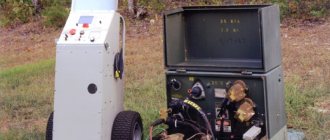
Description of the device for testing the electrical strength of insulation RETOM-6000:
Testing the electrical strength of insulation of electrical installations is mandatory at all stages of their operation. RETOM-6000 was developed , it takes into account the operating experience of the RETOM-2500 :
- the device has become fully automatic, but there is also a manual control mode;
- the maximum voltage of direct and alternating current has been increased to 6 kV;
- the device has a built-in megameter for measuring insulation resistance;
- The channel power has been increased 1.5 times to 2 kV and a mode of up to 1 kV has been added, which makes it possible to more accurately record the magnetization curves of current transformers used for voltages from 110 to 750 kV;
- microprocessor control allows you to record on the indicator the values of voltage, leakage current and the time of supply of increased voltage until the moment of breakdown, select an operating mode with instant shutdown when a breakdown occurs or with afterburning of the channel;
- The new convenient plastic case makes it easier to transport the device to the place of work.
Control methods
Monitoring the condition and electrical strength allows timely detection of defects or aging of the dielectric in the windings of power transformers, bushings and support insulators, high-voltage bushings, power cables and other types of equipment. Thanks to this, devices can be replaced or repaired, the insulating medium can be dried out, or a new winding can be installed. Modern test facilities for testing dielectric strength can use various techniques.
The most popular are:
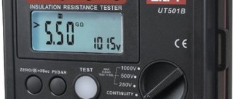
- Insulation resistance measurement is carried out using a megohmmeter with a voltage of 500, 1000 or 2500V, depending on the rating of the unit being tested. The duration and standards are regulated by Appendix 3 of PTEEP , voltage is applied to the internal insulation and resistance is measured.
- High voltage testing - is carried out by applying high voltage to the external insulation, device or part of it through the test transformer of the kenotron installation. This procedure is temporary, and in some cases, pulsed in nature; the technology and test voltage standards are regulated by GOST 246060.1-81 , as well as the more modern GOST R55195-2012 for various types of equipment, paper insulation and others.
- Measuring the dielectric loss angle - in an ideal dielectric this parameter should be equal to 0, but the lower the dielectric strength, the greater the insulation loss. A difference arises between the active and reactive components of the alternating current, which is why tan δ increases, as shown in the figure below:
Rice. 3. Dielectric loss tangent
High voltage insulation test
Testing the insulation of cables, windings of electrical machines and other electrical installations with increased voltage aims to check the presence of the necessary electrical strength margin capable of ensuring trouble-free operation of electrical equipment and identifying and establishing a malfunction in advance.
The high voltage test is carried out using both alternating current of industrial frequency and rectified high voltage current.
Insulation test with increased AC voltage.
The value of the test voltage is determined according to GOST 1516-60, based on operating experience, analysis of the magnitude of internal overvoltages that occur in existing electrical installations and the protective characteristics of arresters against atmospheric overvoltages. In order for the resulting electrical breakdown to be completed and a defect in the insulation to be determined, the test voltage is applied for 1 minute. Long test durations can lead to insulation failure due to thermal runaway even if there are no defects in the insulation. The exception is such insulating organic materials as bakelite, wood, cable paper, etc., in which surface insulation plays the main role. Since dielectric losses in these materials are usually not controlled, the time of application of high voltage during testing is accepted according to GOST as 5 minutes, so that after the end of the test and removal of the voltage, it is possible to check by touch whether there is any local heating. The breakdown voltage of the insulation of devices, transformers and insulators is selected higher than the discharge voltage in the air, which in turn is higher than the test voltage accepted at the manufacturer for new insulators, devices and transformers.
Over time, the insulation strength in operation may decrease, but it should not fall below the established minimum. The insulation is considered to have passed the electrical strength test if there was no breakdown, partial discharges, gas or smoke emissions, and also if the devices did not indicate damage. An insulation breakdown during testing is indicated by an ammeter - by an increase in current and by a voltmeter - by a decrease in voltage. In order not to damage the insulation by partial discharges, if they occur, you should stop testing with high voltage until the defect is eliminated and the insulation is repaired.
The test voltage must be applied:
a) between live and grounded parts (for switching devices in the on and off positions);
b) between live parts of adjacent poles (for switching devices in the on and off positions);
c) between open contacts of the same pole when the device is in the off position.
Insulation testing with increased voltage of direct (rectified) current is used for equipment with large capacitance (cables, capacitors, generators, electric motors, etc.), for testing with alternating current high-power test transformers are required. Therefore, cable lines have been tested with constant (rectified) voltage for quite some time, which has fully justified itself.
The accumulated experience in testing generators and electric motors shows that alternating current tests reveal the majority of defects in the groove part of the insulation, and rectified voltage tests reveal mainly in the frontal part and at the exit from the groove.
Kenotron devices are used to test insulation with rectified voltage. The advantage of testing insulation with rectified voltage is the ability to monitor its condition by measuring leakage currents.
Measuring leakage currents on rectified voltage.
Insulation resistance, as mentioned above, is measured with a megohmmeter, which allows you to read the readings in megohms on the instrument scale when a voltage is applied to the insulation from 500 to 2500 V. However, some defects are not detected at such values of voltage applied to the insulation. To identify such defects, leakage currents are measured using kenotron devices. Based on the leakage currents measured using a microammeter, flowing at given voltage values and counting times, the state of the insulation resistance is judged.
In serviceable and dry insulation, the leakage current will decrease over time, and the faster the insulation is in better condition. If the leakage current at a certain voltage not only does not decrease, but increases over time, then this indicates a strong degree of development of the defect, and in this case it is recommended to carefully inspect the winding (if there is any damage to the insulation) and, if necessary, dry the insulation and then reapply test.
When studying leakage current through insulation, you can also use the method of measuring the voltage and self-discharge time of equipment (electrical machine, etc.) charged to a certain voltage. In this case, a voltmeter or other device is connected in parallel to the equipment under test, which can record the discharge voltage (ball gap, neon lamp with resistance, etc.). The time it takes for the insulation to self-discharge to a certain value will be shorter, the worse the insulation and the smaller its capacity. To assess the state of insulation using the self-discharge method, it is necessary to know experimental data on the self-discharge time (to a certain voltage value) of the tested or similar equipment with good insulation. Leakage currents are not standardized, but are compared with the results of previous tests. Typically, kenotron installations mounted on a vehicle are used to measure leakage currents in cable networks.
Examples of calculations
To calculate the electrical strength of any dielectric, you need to know the operating conditions and geometric parameters, which are then compared with tabular data. For example, if you have a gap with an air dielectric of 2 cm, a voltage of 20 kV will be applied to it.
Next, we calculate the electromagnetic field strength using the formula:
E = U/d;
where E is the field strength, U is the voltage in the electrical circuit, d is the thickness of the insulating layer.
Rice. 4. Calculation example
Then the voltage for this example will be E = 20/2 = 10 kV/cm. Next, we compare the obtained value with the electrical strength for air from the table below:
Table: Electrical strength of materials
| Name of dielectric | Electric strength, kV/cm |
| Dry cable paper | 60 – 90 |
| Oil soaked paper | 100 – 250 |
| Air | 30 |
| Transformer oil | 50 – 180 |
| Mikanite | 150 – 300 |
| Marble | 35 – 55 |
| Paraffin | 150 – 300 |
| Dry electrical cardboard | 80 – 100 |
| Electric cardboard impregnated with oil | 120 – 170 |
| Muscovite mica | 1200 – 2000 |
| Mica phlogopite | 600 – 1250 |
| Glass | 100 – 400 |
| Fiber | 40 – 110 |
| Porcelain | 180 – 250 |
| Slate | 15 – 30 |
| Ebonite | 80 – 100 |
From the table we see that air breakdown can begin at 30 kV/cm; in our calculations the value turned out to be 10 kV/cm, which means that the insulation will normally withstand this operating mode.
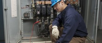
Procedure for checking cable insulation resistance with a megohmmeter
You come to the site and see, for example, the following picture.
Before directly checking the insulation resistance, you must make sure that:
- The cable cores are ringed and marked (read about ringing here)
- on the cable cores where we will supply voltage there is no dirt, scale, or paint (there is no such thing on the cable core, but it may be on the grounding, which is painted, or it may be covered with a layer of rust, then you need to scrape it off with a screwdriver or knife)
- at the other end of the cable no one is working and the cable is disconnected from the load and the power source (it is not worth applying voltage to the installer, who can cut the cable from the other side, or measuring the Rx of the cable with the load, it is also worth making sure that we do not apply high voltage to the secondary circuits and elements that can become unusable at 2500V, so sometimes they are simply switched to 500V)
- the cable is de-energized and measures are in place to prevent accidental supply of voltage to the cable under test (locks, posters, cells removed)
- if the vigilante test (measurement of insulation resistance) is combined with high-voltage tests, then you need to make sure that there is a person at the second end of the cable (the second end is opposite from the test site) or the room is locked and fenced with posters posted
- The megohmmeter is in good condition and suitable for use (verification mark on the body and the ends of the device are tested)
- you have the right and qualifications to work with a megohmmeter and perform this type of work (group 3 on electrical safety and an unexpired test of special knowledge, plus a medical examination)
- the megohmmeter wires must have high insulation (here you can also do the following: connect the two megohmmeter wires and apply voltage - the value should be zero, since there is no insulation between the wires, and if separated, then infinity - since the air resistance is high)
8-11. ELECTRICAL INSULATION STRENGTH TEST
The electrical strength of insulation (breakdown) test is carried out by applying to this insulation for 1 min.
AC voltage 50
Hz
is almost sinusoidal. The value of this test voltage is indicated in table. 8-6.
The rise and fall of the test voltage must be smooth 1
and start with a voltage of no more than 7 test voltage. Each independent electrical circuit is tested in turn, one pole of the test voltage source is applied to the terminal of the winding under test, and the other is applied to the grounded body of the machine, to which all other (not participating in the test) windings are electrically connected during the testing of this winding. .
Multiphase windings interconnected are considered one circuit if the beginning and end of each phase are not connected to special terminals. In this case, the entire multiphase winding is tested from the body as a whole. If there are terminals for the beginning and end of each phase, testing from the housing is done alternately for each phase with other phases connected to the housing.
If one of the windings of the machine is connected to the machine body during the nominal operating mode, then during testing of the electrical strength of the insulation of such a winding it must be disconnected from the machine body.
If during repairs a complete replacement of any winding is made with a new one, then this winding is tested for full breakdown voltage for a newly manufactured machine in accordance with GOST 183-55.
If during repairs only part of the winding is replaced, and part of the winding remains old, used, then the electrical strength of the entire winding is tested with a voltage equal to 1.3 of the rated voltage of the machine, but not less than 0.5 of the test voltage specified in the table. 8-6.
Verification tests of electrical insulation strength after delivery of the machine to the site of assembly and drying
1 For more details, see GOST 183-55.
Table 8-6
test voltage for electrical testing
insulation strength of windings relative to the machine body
and between windings (according to GOST 183-55)
Electrical machine or parts thereof
| Test voltage (rms value) | |
| Machines with a power of at least | 500 V plus double nominal |
| 1 ket (or 1 | nal voltage |
| machines at rated voltage | |
| not more than 36 v | |
| Machines with power from 1 kW | 1,000 plus double no- |
| [or 1 kva) to 3 ket (or 3 | nominal voltage |
| inclusive at nominal | |
| voltage above 36 V | |
| a) machines with more power | 1 000 8 plus double no- |
| 3 ket (or 3 | nominal voltage, but not |
| including those listed in paragraph 3, b | less than 1,500 v |
| of this table, at nominal | |
| voltage over 36 V | |
| b) Machines with power from | |
| 1 000 ket (or 1,000 | |
| higher for rated voltage: | |
| up to 3 300 V inclusive | 1,000 plus double no- |
| nominal voltage | |
| over 3,300 to 6,600 6 incl. | 2.5 times nominal |
| carefully | yarning |
| over 6,600 in | 3 000 V plus double but- |
| nominal voltage | |
| Excitation windings synchronous | Ten times nominal |
| generators with rated | voltage of the excitatory system |
| exciter voltage | system, but not less than 1,500 V And |
| system does not exceed 800 V | no more than 3,500 in |
| Excitation windings synchronous | |
| motors and synchronous | |
| Pspа 1 UpUD, a) if the machine is intended | Ten times nominal |
| for direct start from | voltage of the excitatory system |
| AC side with ob- | system, but not less than 1,500 in |
| skein of excitement, closed | |
| for resistance or use | |
| source of your food | |
| b) the same, but intended | 1,000 plus tenfold |
| for starting with open winding | rated voltage |
| some kind of excitation, subdivided | alarm system, but not |
| noah at the section | less than 1,500 v |
| c) the same, but intended | 1000 V plus 20-fold but- |
| for starting with open circuit | minimum exciter voltage |
| a skein of excitement, not sex | body system, but no less |
| tioned | 1,500 v and no more than 8,000 v |
Continuation of the table. 8-6
| Electrical machine or parts thereof | Test voltage (rms value) |
| d) synchronous motors and syn- | Ten times nominal |
| chronic compensators, triggered | voltage of the excitatory system |
| special starting motors | system, but not less than 1,500 in |
| lyami | |
| Exciters for electrical | |
| cars | |
| a) exciters for electrical | 1,000 plus double no- |
| mechanical machines, except synchronous | nominal voltage, but not |
| nykh | less than 1,500 v |
| b) exciters for synchronous | Ten times nominal |
| new generators that have new | voltage, but not less than 1,500 V |
| minal voltage | and no more than 3,500 per |
| system does not exceed | |
| 800 v | |
| c) exciters for synchronous | Ten times nominal |
| motors and synchronous | voltage, but not less than 1,500 V |
| compensators | |
| Secondary windings are asynchronous | |
| nal engines that are not in | |
| continuous short-circuited | |
| condition: | |
| a) for engines, I admit- | 1 000 V plus four times |
| anti-inhibition braking | rated voltage auto- |
| esteem | primary winding |
| b) for engines not intended | 1 000 V plus double but- |
| designated for braking | nominal secondary voltage |
| opposition | no winding |
| Grouped electrical | If tested |
| Chinese machines and apparatus | a group made up of several |
| some new ones, just tired | |
| renovated and combined together | |
| those electrical machines and app- | |
| parathas, each of which | |
| the machine and each device are pro- | |
| there were electrical tests | |
| strength, then test | |
| new voltage should not | |
| exceed 85% of the test | |
| voltage of that machine (or | |
| that device) which has this | |
| lowest voltage | |
| produced within 1 min voltage equal to | |
| 75% voltage specified | in the table. |
Contents Previous § Next