Verification: test or measurement?
As a first step, it is useful to clarify the difference between two types of testing that are often confused - dielectric strength testing and insulation resistance testing.
The dielectric strength test, also called the flashover test, determines the ability of an insulation to withstand a medium-duration voltage surge without sparking. In fact, such a voltage surge can be caused by lightning or induction as a result of a faulty power line. The main purpose of this test is to ensure compliance with building codes regarding creepage distances and clearances. This test is often performed using AC voltage, but the test also uses DC voltage. This type of measurement requires the use of high voltage cable testing facilities. The result is a voltage value, usually expressed in kilovolts (kV). Electrical strength testing can be devastating if it fails, depending on the testing levels and the energy capabilities of the instrument. Therefore, this method is used for routine testing on new or refurbished equipment.
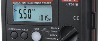
Under normal test conditions, insulation resistance measurement is a non-destructive test. This measurement is performed using a lower DC voltage than the dielectric strength test and gives a result expressed in kOhms, MOhms, GOhms or TOhms. The resistance value indicates the quality of the insulation between two conductors. Since this test is non-destructive, it is particularly suitable for monitoring the aging of the insulation of operating electrical equipment or installations. An insulation tester, also called a megger, is used for this measurement (meggers are available with a range of up to 999 GΩ).
What can insulation monitoring be like?
There are several types of checks to ensure that your installation is safe. The most common is periodic insulation monitoring, which is carried out once every 6-24 months, depending on the specific properties of the object. In addition, spot checks can also be used to determine the integrity of lines that are suspected of being safe. Finally, for such large installations as the power supply of a store, industrial enterprise, or residential complex, special devices are used that allow continuous monitoring.
When a malfunction is detected, the signal is transmitted to the dispatch console, which allows you to immediately respond to it and fix the problem. Such a system also allows you to quickly determine the point of rupture of the containment and the formation of a leak.
Example of a technical report
Back
Forward
Typical causes of insulation failure
Since measuring insulation resistance with a megger is part of a broader preventative maintenance policy, it is important to understand the reasons why insulation performance may deteriorate. Only this will allow you to take the right steps to eliminate them.
The causes of insulation failure can be divided into five groups. However, it must be borne in mind that in the absence of any corrective measures, various causes will overlap each other, leading to insulation breakdown and equipment damage.
Electrical loads
Basically, electrical loads are associated with the deviation of the operating voltage from the nominal value, and both overvoltage and undervoltage have an impact on the insulation.
Mechanical loads
Frequent sequential starts and stops of equipment can cause mechanical stress. This also includes problems with balancing rotating machines and any direct stress on cables and installations in general.
Chemical influences
The presence of chemicals, oils, aggressive fumes and dust generally negatively affects the performance of insulating materials.
Stresses associated with temperature fluctuations:
In combination with the mechanical stresses caused by successive starts and stops of equipment, the properties of insulating materials are also affected by the stresses generated by expansion and contraction. Working at extreme temperatures also causes aging of materials.
Environmental pollution
Mold and foreign particles in warm, humid environments also contribute to the deterioration of the insulation properties of plants and equipment.
The table below shows the relative frequency of various causes of motor failure.
External pollution:
In addition to sudden insulation failures due to extreme events such as floods, factors that reduce the insulation effectiveness of an operating installation combine, sometimes reinforcing each other. Ultimately, in the long term, without constant monitoring, this will lead to situations that become critical from the point of view of human safety and normal operation. Regular testing of the insulation of installations or electrical machines is therefore a useful way to monitor the condition of the insulation, allowing necessary action to be taken before damage occurs.
The principle of measuring insulation resistance and the factors influencing it
Insulation resistance measurement is based on Ohm's law. By applying a known DC voltage at a level lower than the dielectric test voltage and then measuring the current value, it is very easy to measure the resistance value. In principle, the value of the insulation resistance is very large, but not infinite, therefore, when measuring a small flowing current, the megohmmeter indicates the value of the insulation resistance in kOhm, MOhm, GOhm and even in TOhm (on some models). This resistance characterizes the quality of the insulation between two conductors and can indicate the risk of leakage current.
The value of the insulation resistance, and therefore the amount of current that flows when DC voltage is applied to the circuit under test, is influenced by a number of factors. Such factors include, for example, temperature or humidity, which can significantly affect the measurement results. First, let's analyze the nature of the currents flowing during an insulation measurement, using the hypothesis that these factors do not affect the measurement being made.
The total current flowing in the insulating material is the sum of three components:
- Capacity. To charge the capacitance of the insulation under test, a capacitor charging current is required. This is a transient current that starts at a relatively high value and drops exponentially to a value close to zero as the circuit under test becomes electrically charged. After a few seconds or tenths of a second, this current becomes insignificant compared to the measured current.
- Absorption. Absorption current corresponding to the additional energy required to reorient the molecules of the insulating material under the influence of an applied electric field. This current drops much more slowly than the capacitance charging current; sometimes it takes several minutes to reach a value close to zero.
- Leakage current or conduction current. This current characterizes the quality of the insulation and does not change over time.
The graph below shows these three currents as a function of time. The time scale is arbitrary and may vary depending on the insulation being tested.
To ensure proper test results on very large motors or very long cables, minimizing capacitive and absorption currents can take 30 to 40 minutes.
When a constant voltage is applied to a circuit, the total current flowing in the insulator under test varies as a function of time. This implies a significant change in insulation resistance.
Before looking in detail at the various measurement methods, it would be useful to take another look at the factors that influence insulation resistance measurement.
Effect of temperature
Temperature causes a quasi-exponential change in the insulation resistance value. In the context of a preventive maintenance program, measurements should be made under uniform temperature conditions or, if this is not possible, should be corrected relative to a reference temperature. For example, a 10°C increase in temperature reduces the insulation resistance by approximately half, while a 10°C decrease in temperature doubles the insulation resistance value.
The level of humidity affects the insulation according to the degree of contamination of its surface. Never measure insulation resistance when the temperature is below the dew point.
Correction of insulation resistance depending on temperature (source IEEE-43-2000)
Test methods and interpretation of results
Short-term or spot measurement
This is the simplest method. It involves applying test voltage for a short time (30 or 60 seconds) and recording the insulation resistance value at this moment. As stated above, this direct measurement of insulation resistance is significantly influenced by temperature and humidity, so the measurement should be standardized at a reference temperature and the humidity level should be recorded for comparison with previous measurements. Using this method, you can analyze the quality of the insulation by comparing the current measured value with the results of several previous tests. Over time, this will provide more reliable information about the insulation performance of the installation or equipment being tested compared to a single test.
If the measurement conditions remain identical (same test voltage, same measurement time, etc.), then with periodic measurements, a clear assessment of the insulation condition can be obtained by monitoring and interpreting any changes. After recording the absolute value, it is necessary to analyze the change over time. Thus, a measurement showing a relatively low insulation value that is nonetheless stable over time should theoretically be less of a concern than a significant decrease in insulation resistance over time, even if the insulation resistance is higher than the recommended minimum value. In general, any sudden drop in insulation resistance indicates a problem that needs to be investigated.
The graph below shows an example of insulation resistance readings for an electric motor.
At point A, the insulation resistance decreases due to aging and dust accumulation.
A sharp drop at point B indicates insulation failure.
At point C, the fault has been cleared (the motor winding has been rewound) and the insulation resistance has returned to a higher value that remains stable over time, indicating good insulation condition.
Test methods based on the influence of test voltage application time (PI and DAR)
These methods involve sequentially measuring insulation resistance values at specified times. They have the advantage of not being particularly affected by temperature, so they can be used without correction of the results, unless the test equipment is exposed to significant temperature fluctuations during the test.
These methods are ideal for preventive maintenance of rotating machines and for insulation monitoring.
If the insulating material is in good condition, the leakage current or conduction current will be low, and the initial measurement will be greatly influenced by the capacitance charging and dielectric absorption currents. As the test voltage is applied, the measured insulation resistance value increases over time as these interference currents decrease. The stabilization time required to measure insulation in good condition depends on the type of insulating material.
If the insulating material is in poor condition (damaged, dirty and wet), the leakage current will be constant and very high, often exceeding the capacitance charging and dielectric absorption currents. In such cases, the insulation resistance measurement very quickly becomes constant and stabilizes at a high voltage value.
Studying the change in the insulation resistance value depending on the time of application of the test voltage makes it possible to assess the quality of the insulation. This method allows conclusions to be drawn even if no insulation measurement log is kept. However, it is recommended that the results of periodic measurements performed in the context of a preventive maintenance program be recorded.
Polarization Index (PI)
Using this method, two readings are taken at 1 minute and 10 minutes, respectively. The ratio (without dimensions) of the 10-minute insulation resistance value to the 1-minute value is called the polarization index (PI). This indicator can be used to assess the quality of insulation.
The polarization index measurement method is ideal for testing solid insulation circuits. This method is not recommended for use on equipment such as oil-immersed transformers as it produces poor results even if the insulation is in good condition.
IEEE Recommendation 43-2000, Recommended Test Methods for Insulation Resistance of Rotating Machines, specifies a minimum polarization index (PI) value of 2.0 for AC and DC rotating machines in temperature classes B, F, and H. In general, a PI value greater than 4 is a sign of excellent insulation, while a value below 2 indicates a potential problem.
PI = R (10-minute insulation measurement) / R (1-minute insulation measurement)
The results are interpreted as follows:
| PI value (norm) | Insulation state |
| <2 | Problematic |
| From 2 to 4 | good |
| > 4 | Excellent |
Dielectric Absorption Rate (DAR)
For installations or equipment containing insulating materials in which the absorption current decreases quickly, a measurement at 30 seconds and 60 seconds may be sufficient to assess the condition of the insulation. The DAR coefficient is determined as follows:
DAR = R (60 second insulation measurement) / R (30 second insulation measurement)
The results are interpreted as follows:
| DAR value (norm) | Insulation state |
| <1,25 | Unsatisfactory |
| <1,6 | Normal |
| >1,6 | Excellent |
Method based on the effect of changing test voltage (step voltage testing)
The presence of contamination (dust, dirt, etc.) or moisture on the insulation surface is usually clearly detected by time-dependent resistance measurements (PI, DAR, etc.). However, this type of testing, conducted using a low voltage relative to the dielectric voltage of the insulating material being tested, can sometimes miss signs of insulation aging or mechanical damage. A significant increase in the applied test voltage can, in turn, cause damage at these weak points, which will lead to a significant decrease in the measured insulation resistance value.
To be effective, the ratio between voltage steps must be 1 to 5, and each step must be the same in time (typically 1 to 10 minutes), while remaining below the classic dielectric test voltage (2Un + 1000 V). The results obtained with this method are completely independent of the type of insulation and temperature, because it is not based on the internal value of the insulator being measured, but on the effective reduction of the value obtained after the same time for two different test voltages.
A decrease in insulation resistance value of 25% or more between the first and second measurement steps is evidence of insulation deterioration, which is usually associated with the presence of contamination.
Dielectric Dissipation (DD) Test Method
The dielectric leakage (DD) test, also known as reabsorption current measurement, is performed by measuring the dielectric leakage current on the equipment under test.
Since all three current components (capacitance charging current, polarization current, and leakage current) are present during a standard insulation test, the determination of polarization or absorption current may be influenced by the presence of leakage current. Instead of attempting to measure polarization current during insulation testing, dielectric dissipation (DD) testing measures depolarization current and capacitance discharge current after insulation testing.
The measurement principle is as follows. First, the equipment under test is charged for a time sufficient to reach a steady state (capacitance charging and polarization is complete and the only current flowing is leakage current). The equipment is then discharged through a resistor inside the megger and the current flowing is measured. This current consists of the capacitance charging current and the reabsorption current, which together give the total dissipation current in the dielectric. This current is measured after a standard time of one minute. The electric current depends on the total capacitance and the final test voltage. The DD value is calculated using the formula:
DD = Current after 1 minute / (Test Voltage x Capacitance)
The DD test identifies excess discharge currents when one of the layers of multi-layer insulation is damaged or contaminated. In spot tests or PI and DAR tests, such a defect may be missed. For a given voltage and capacitance, the discharge current will be higher if one of the insulation layers is damaged. The time constant of this individual layer will no longer be the same as the other layers, resulting in a higher current value compared to undamaged insulation. Homogeneous insulation will have a DD value close to zero, and acceptable multi-layer insulation will have a DD value of up to 2. The table below indicates the condition depending on the DD value obtained.
| DD (norms) | State |
| > 7 | Very bad |
| From 4 to 7 | Bad |
| From 2 to 4 | Doubtful |
| <2 | Normal |
Note: This measurement method is temperature dependent, so each test attempt must be performed at a standard temperature, or at least the temperature must be recorded along with the test result.
High Resistance Insulation Testing: Using Jack G on a Megger
When measuring insulation resistance values (above 1 GOhm), the accuracy of the measurements can be affected by leakage currents flowing along the surface of the insulating material through moisture and contaminants present on it. The resistance value is no longer high and therefore negligible compared to the resistance of the insulation being evaluated. To eliminate surface current leakage that reduces the accuracy of insulation measurement, some megohmmeters have a third socket designated G (Guard). This socket bypasses the measurement circuit and reintroduces surface current to one of the test points, bypassing the measurement circuit (see figure below).
When choosing the first circuit, without using socket G, the leakage current i and the unwanted surface current I1 are simultaneously measured, so the insulation resistance is measured incorrectly.
However, when choosing the second scheme, only the leakage current i is measured. Connection to socket G allows the surface current I1 to be diverted, so the insulation resistance measurement is carried out correctly.
The G socket must be connected to a surface that carries surface currents and is not an insulator such as cable or transformer insulation. Knowing the possible paths for test currents to flow through the element under test is critical to selecting the connection location to socket G.
Insulation resistance monitoring
.
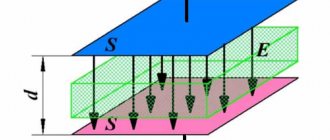
The insulating sheaths of cables and wires are not ideal dielectrics. This means that a leakage current I flows through the sheath of any wire,
the source of which is the SES generator or any other source of electricity.
The resistance of the wire sheath to the flow of said current is called insulation resistance
R=
where U -
voltage of the electricity source.
Figure 8.5. Schemes of electrical networks of direct (c) and alternating (b)
current with different types of insulation resistance
There are 2 types of insulation resistance (Fig. 6.6, a):
- a separate wire relative to the housing r
(
r
);
— between current-carrying conductors r
.
An increase in leakage current indicates a decrease in insulation resistance. .
The leakage currents of each element of the cable length, closing through the source, form parallel branches. Therefore, the longer the line, the more parallel branches for the specified currents and the lower the insulation resistance of the line.
Leakage currents are created not only by power lines, but also by sources and receivers of electricity through the insulation resistance of the windings of electrical machines.
Therefore, the simultaneous switching on of a large number of receivers, each of which has a sufficiently high insulation resistance, can lead to a significant reduction in the insulation resistance of the ship's network.
Leakage currents, in addition to the core current, cause additional heating of the insulation and accelerate its aging. Therefore, heating of the insulation of current-carrying conductors of cables and wires should not exceed the temperature limits (ºС) allowed by the insulation class
The condition of the insulation is also significantly influenced by external factors: humidity and air temperature, vibration, etc.
A decrease in insulation resistance below established standards can cause a fire in electrical equipment or cause electric shock to a person.
Systematic monitoring of insulation resistance can be carried out both when the voltage is removed and when it is present on the electrical equipment.
On ships, to measure the insulation resistance of a de-energized SES, special electrical measuring instruments are used - portable megohmmeters. The choice of megger is made taking into account the voltage of the network in which the measurement is being made.
The operating principle of these devices is to artificially create and subsequently measure a leakage current, the value of which depends on the insulation resistance. Therefore, megaohmmeters have a power source and a measuring device with a scale graduated in kilo-ohms or mega-ohms. Megometers come in induction and non-induction types.
The rules for measuring insulation resistance are as follows. First, check the serviceability of the megohmmeter, for which the “ L”
("line") and "
Z
"
(
"ground", i.e. body) and, by rotating the handle, make sure that the instrument needle is set to the zero mark.
Then turn off the voltage from the measurement object, after which it is imperative to check the absence of voltage with a working indicator.
The insulation resistance reading should be carried out 1 minute after applying the operating voltage of the megohmmeter.
It is believed that after this time, the charge of the capacitors of the measurement objects - electrical networks or machines - will end, and the leakage currents through the capacitors that create measurement errors will decrease to zero.
After completing the measurements, it is necessary to remove the charge from the network by briefly grounding the cores or connecting them to each other. This will avoid electric shock to a person if they accidentally touch the wires.
Various methods are used to automatically monitor the insulation resistance of electrical networks, but the most widely used method is the application of direct current to the controlled alternating current network.
The recently developed insulation diagnostic system minimizes the time required to search for a damaged section or element of the electrical network. The system includes 4 blocks (Fig. 6.13).
Figure 8.6. Block diagram of the automatic insulation diagnostic system of SEES
Functional block BF
combines the functions of a power source for the remaining blocks of the system and a block for generating control voltages with their subsequent distribution to the ship's network and to de-energized elements of the SEPS.
In addition, this unit supplies the BI
with voltages proportional to the leakage currents of the entire SEES and its individual elements.
In the BI
the indicated voltages are converted and measured.
From the output of this block, voltages proportional to the active insulation resistances of the entire SEES and its individual elements are supplied to the input of the control block BC,
in which they are compared with the setpoint voltages.
When the insulation resistance decreases to an unacceptable level, the BC
allows the operation of the
BV output block.
The latter turns on the alarm, indicates the number of the SEES element with an insulation defect and registers the control results.
The described system allows you to automate the shutdown of SEPS elements with reduced insulation and the simultaneous activation of backup ones. Its use as a control subsystem of the SEPS makes it possible to almost uninterruptedly supply electric power to the STS, and, first of all, to the means that ensure navigation safety.
Test voltage standards for cables/equipment
| Operating voltage of cable/equipment | DC test voltage standards |
| 24 to 50 V | 50 to 100 VDC |
| 50 to 100 V | 100 to 250 VDC |
| 100 to 240 V | 250 to 500 V DC |
| 440 to 550 V | 500 to 1000 V DC |
| 2400 V | 1000 to 2500 V DC |
| 4100 V | 1000 to 5000 V DC |
| From 5000 to 12,000 V | 2500 to 5000 V DC |
| > 12,000 V | 5000 to 10,000 VDC |
The table above shows the recommended test voltages according to the operating voltages of installations and equipment (values taken from IEEE Guide 43-2000).
In addition, these values are specified for electrical appliances in a wide variety of local and international standards (IEC 60204, IEC 60439, IEC 60598, etc.).
In France, for example, the NFC15-100 standard provides test voltage and minimum insulation resistance values for electrical installations (500 V DC and 0.5 MΩ for rated voltages from 50 to 500 V).
However, you are strongly advised to contact the cable/equipment manufacturer for their own recommendations on the required test voltage.
Insulation monitoring
To maintain the insulation in good condition, it is necessary to monitor its resistance, for which periodic and continuous methods of measuring and testing are used.
A) RM is measured in a switched-off installation once a year, out of turn, when defects are detected, after repairs. The measured insulation resistance must not be lower than the standard Riz³ Rizdop. Megometers for the appropriate voltages are used for measurements.
B) Insulation testing with increased voltage is carried out in a switched-off installation during repairs of electrical equipment, as well as when damage is detected. This method is effective for identifying local defects and checking the dielectric strength of insulation, i.e. ability to withstand operating voltage for a long time. During the test, a voltage Uapp is applied for 1 min several times (in accordance with the PUE) higher than the operating voltage Upab.
B) Insulation monitoring without disconnecting the operating voltage is called continuous.
The simplest is the three voltmeter method. In installations up to 1000 V, voltmeters are connected directly to the phases and ground. With proper insulation, when the resistance of all phases relative to the ground is the same, each of the voltmeters will show the phase voltage. If the resistance of one of the phases decreases noticeably, then its voltmeter will show a decrease in voltage, and the other two will show an increase.
Fig. 10. Insulation monitoring circuit with voltmeters
If phase 1 is shorted to ground, its voltmeter will show zero, and the other two will show linear voltages.
The disadvantages of this method are the following: the circuit does not respond to a symmetrical decrease in Riz, all three phases; the circuit reacts to changes in capacitance Siz.
The second method is the method of imposing a constant operational current; for workers is most common, because meets all requirements for continuous insulation monitoring schemes. The source of constant operating current Uist ensures the flow of leakage current Iout, the value of which depends on the total active insulation resistance of the controlled network ( Iout = f(Rout)). When the resistance decreases, any of the phases below the set value Iut reaches the relay setting current, the relay is activated and its contacts influence the actuator.
Fig. 11. Scheme of continuous monitoring of insulation with operational current
Operating current can be provided from an external source (as in the diagram in Fig. 11) or from a rectifier excluded from the controlled network (so-called valve circuits).
The advantages of this method are as follows:
the circuit responds to a symmetrical and asymmetrical decrease in Rout;
there is an alarm about a decrease in Rlow Rout; The input impedance of the circuit is high, which ensures reliability.
In networks with a grounded neutral, the insulation resistance has little effect on the current of a person touching a bare wire. But even in this network, resistance control is necessary, because prevents short circuits to ground and electrical equipment and thereby increases electrical safety. However, the application of continuous monitoring in such networks is associated with certain difficulties.
Safety in Insulation Testing
Before testing
A. To ensure that the test voltage is not applied to other equipment having an electrical connection to the circuit under test, the test must be performed on a disconnected, non-conducting installation.
B. Make sure the circuit is discharged. It can be discharged by short-circuiting the terminals of the equipment and/or shorting them to ground for a certain time (see discharge time).
C. If the equipment being tested is in a flammable or explosive environment, special protection is required because if the insulation is damaged, sparks may occur when the insulation is discharged (before and after testing) and during testing.
D. Due to the presence of DC voltage, which can be quite high, it is recommended that access by other personnel be restricted and personal protective equipment (such as safety gloves) suitable for working on electrical equipment be worn.
E. Use only connecting cables that are suitable for the test being performed; Make sure the cables are in good condition. At best, unsuitable cables will lead to measurement errors, but more importantly, they can be dangerous.
After testing
At the end of the test, the insulation will have accumulated significant energy which must be released before any other operations can be carried out. A simple safety rule is to allow the equipment to discharge for five times the charging time (last test time). To discharge the equipment, you can short-circuit its terminals and/or connect them to ground. All megohmmeters manufactured by Chauvin Arnoux are equipped with built-in discharge circuits that automatically ensure the required safety.
Testing safety
Before testing
- To ensure that the test voltage is not applied to other equipment having an electrical connection to the circuit under test, the test must be performed on a disconnected, non-conducting installation.
- Make sure the circuit is discharged. It can be discharged by short-circuiting the terminals of the equipment and/or shorting them to ground for a certain time (see discharge time).
- If the equipment being tested is in a flammable or explosive environment, special protection is required because, if the insulation is damaged, sparks may occur when the insulation is discharged (before and after the test), as well as during testing.
- Due to the presence of DC voltage, which can be quite high, it is recommended that access by other personnel be restricted and personal protective equipment (such as safety gloves) designed for working on electrical equipment be worn.
- Only use connecting cables that are suitable for the test being carried out; Make sure the cables are in good condition. At best, unsuitable cables will lead to measurement errors, but more importantly, they can be dangerous.
After testing
At the end of the test, the insulation will have accumulated significant energy which must be released before any other operations can be carried out. A simple safety rule is to allow the equipment to discharge for five times the charging time (last test time). To discharge the equipment, you can short-circuit its terminals and/or connect them to ground. All megohmmeters manufactured by Chauvin Arnoux are equipped with built-in discharge circuits that automatically ensure the required safety.
FAQ
The result of my measurements is x MOhm. This is fine?
What should the insulation resistance be? There is no single answer to this question. The exact answer to this can be provided by the equipment manufacturer or the relevant standards. For low-voltage installations, the minimum value can be considered to be 1 MOhm. For installations or equipment with higher operating voltages, a minimum value of 1 MΩ per kV can be used, while the IEEE guidelines for rotating machines specify a minimum insulation resistance of (n + 1) MΩ, where n is the operating voltage in kV .
What test leads should be used to connect the megger to the installation under test?
The wires used on megohmmeters must have specifications suitable for the measurements being made in terms of the voltages used or the quality of the insulating materials. Using inappropriate test leads may cause measurement errors or even be dangerous.
What precautions should be taken when measuring high insulation resistance?
When measuring high insulation resistance values, in addition to the safety rules stated above, the following precautions must be observed.
- Use the special G (Guard) socket (described in the dedicated section above).
- Use clean, dry wires.
- Lay the wires at a distance from each other and without contact with any objects or the floor. This will limit the possibility of leakage currents occurring in the measuring line itself.
- Do not touch or move the wires during measurement to avoid interfering capacitive effects.
- Allow the required time to stabilize the measurement.
Why don't two consecutive measurements always give the same result?
The application of high voltage creates an electric field that polarizes the insulating materials. It is important to understand that it will take a significant amount of time for insulation materials to return to their pre-test condition after testing is completed. In some cases, this may take longer than the discharge time stated above.
How do I test the insulation if I can't shut down the installation?
If it is not possible to turn off the power to the installation or equipment under test, the megger cannot be used. In some cases, it is possible to test without removing the voltage by using special clamps to measure the leakage current, but this method is much less accurate.
How can isolation control save the situation?
The process of reducing insulation is quite lengthy. Using the Phlox insulation monitoring relay, you can find out about a decrease in insulation in advance and block the transformer protection and issue a warning signal.
To do this, it is necessary to connect a shunt resistor with a resistance of 3.3 kOhm in parallel to the discrete input of the relay protection device or the receiving gas protection relay, thereby providing a circuit for the flow of current through the insulation and the Flox measurement circuit. The Phlox relay has an adjustable response threshold - 400 µA or 200 µA, which makes it possible to detect a decrease in insulation below a value of 0.55 or 1.1 MOhm at a nominal operating circuit voltage of 220 V.
An insulation resistance equal to 1 MOhm is the minimum permissible for secondary circuits in accordance with STO 34.01-23.1-001-2017 PJSC Rosseti, a value equal to 0.5 MOhm is the minimum permissible according to clause 1.8.25 of the PUE. If the insulation resistance decreases below the permissible threshold, it is necessary to check the secondary switching circuits for damage and other reasons for the decrease in insulation. The Phlox relay operates with a delay of one second. This is necessary to tune out interference and various processes not related to a decrease in insulation resistance.
Figure 5 – Connection of gas protection and Phlox insulation monitoring relay
When triggered, Phlox closes its three output relays, which generally act on the warning alarm, the sets of main and backup protection of the transformer, thereby ensuring that the action of the gas protection of this stage is transferred to the alarm (Figure 5).
With a further decrease in resistance below a critical value, the voltage at the discrete input of the relay protection device rises to the value at which the protection is triggered. This false alarm does not lead to the transformer being turned off, because The protection action was promptly switched from shutdown to alarm thanks to the operation of the Phlox relay.
If the insulation resistance gradually decreases and the current through the Phlox relay increases, then when the value reaches 35 mA (which corresponds to 3.2 kOhm of insulation resistance), the Phlox relay will release the contacts of the output relays, thereby releasing the gas protection.
To ensure high reliability of this solution, the Phlox relay measuring circuit contains only one passive element - a measuring shunt. This solution does not lead to disruption of the gas protection shutdown circuit when the Phlox power supply disappears or fails.
How to choose an insulation resistance meter (megger)?
When choosing an insulation resistance tester, you need to ask the following key questions:
- What is the maximum test voltage required?
- What measurement methods will be used (spot measurements, PI, DAR, DD, voltage step)?
- What is the maximum insulation resistance value that will be measured?
- How will power be supplied to the megger?
- What are the storage options for measurement results?
Examples of insulation resistance measurements
Insulation measurement on electrical installations, electrical equipment
Insulation measurement on a rotating machine (electric motor)
Measuring insulation on power tools
Measuring insulation on a transformer
Transformer insulation resistance is measured as follows:
a. Between high voltage winding and low voltage winding and ground
b. Between low voltage winding and high voltage winding and ground
c. Between high voltage winding and low voltage winding
d. Between high voltage winding and ground
e. Between low voltage winding and ground
How is insulation resistance continuously monitored?
In order to ensure continuous monitoring of the power line, along with protective devices, a specialized unit is installed in it - the so-called setpoint. It works on a principle similar to an RCD - in particular, when a differential current is detected, the device transmits an alarm signal and also displays which line connected to it suffered from a negative impact that led to a break. Insulation monitoring is carried out by measuring the resistance of the wire in relation to the ground - this allows you to obtain the most reliable information about safety.
If you need to continuously monitor the insulation resistance, it is worth selecting a setpoint with the correct characteristics. In particular, such a selection is carried out based on the number of connected lines, as well as the possibility of detecting a break in a specific area. In addition, you should also focus on the level of permissible resistance of the device relative to the ground, as well as voltage and current. The device connection diagram is as follows: