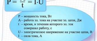
What is an electrical circuit called?
EC is a complex of elements with the help of which electrical energy is created, transmitted and consumed. These elements, or sections, contain sources of electrical energy, as well as intermediate devices and conductors between them, ensuring the continuity of connections.
What is another name for an electrical circuit?
Sources of electrical energy are devices that produce current through physical, chemical or light transformations.
Important! Receivers of electricity are devices whose operation directly depends on the activity of the source.
Intermediate elements with functional devices serve to transmit electrical energy from sources to receivers. Depending on the purpose, they directly transmit energy with specific source parameters.
The concept of an electrical circuit and its elements
Definition 1
An electrical circuit is considered to be a complex of electrical devices that form a path for the passage of electric current and are focused on the transmission, distribution and mutual transformation of electrical and other types of energy.
Finished works on a similar topic
- Course work Active and passive electrical circuit 490 rub.
- Abstract Active and passive electrical circuit 270 rub.
- Test work Active and passive electrical circuit 230 rub.
Receive completed work or specialist advice on your educational project Find out the cost
Electromagnetic processes occurring in electrical circuit devices can be described by such concepts as electromotive force, voltage and current.
Electrical circuits are called direct current circuits when the receipt of electrical energy, as well as its transmission and transformation, is carried out under the condition that the current and voltage remain constant over time.
$\frac{di}{dt} = 0$
$\frac{du}{dt} = 0$
The basic elements of the electrical circuit will be the sources and receivers of electricity that connect the wires.
Each electrical circuit includes a variety of devices and objects responsible for creating paths for the passage of electric current. Conventionally, all elements of the electrical circuit are divided into three components:
- power supplies that generate electricity;
- elements that convert electricity into other types of energy (receivers);
- transmitting devices (wires and other installations responsible for ensuring quality and voltage level).
In electrical circuits, the connection of consumers can be combined, serial, or parallel.
Need advice on your academic work? Ask a question to the teacher and get an answer in 15 minutes! Ask a Question
Types of electrical circuit
There are 3 main types of connection of energy consumers:
- Serial connection
The overall resistance indicator of a closed EC invariably increases with an increase in the number of consumers. Based on this rule, we can conclude that the impedance indicator will be the sum of the individual values of each device connected to the circuit. Any device connected to the network receives only a fraction of the voltage, since the total indicator of the energy chain is divided by the number of consumers.
Connection of EC elements - main types
- Parallel connection
Such a diagram gives a complete understanding of the principle of operation of an electrical circuit. If this process occurs directly at the branching point, then the current passes further through two loaded sections, which generates a certain resistance. As a result, its value is equal to the sum of the currents diverging from a given point. As for the resistance, it decreases significantly as the overall patency of the EC increases. A parallel connection allows all devices to function independently of each other.
Important! If one of the circuit elements fails or a short circuit occurs, then the remaining consumers will continue to operate with malfunctions, but the circuit will not completely break.
- Combined connection
Electrical appliances can be connected in both ways - parallel and serial, and this type of connection will be called combined. For example, you can consider protective equipment. To connect it, you can use a serial option, but this method may cause an unexpected break in the circuit.
Note! The combined connection allows you to distribute the load on the lines to prevent overload.
Nonlinear and linear
Nonlinear elements give EC properties that cannot be achieved in linear circuits (voltage stabilization, DC amplification). They are usually divided into uncontrollable and controllable. The first option includes bipolar devices. Their main purpose is full-fledged operation without the influence of a control factor (semiconductor thermistors or diodes). The second option includes multi-terminal networks used when they are exposed to a control factor (transistors and thyristors).
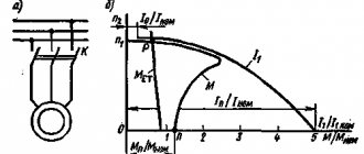
The properties of nonlinear elements are expressed in current-voltage characteristics. They display the dependence of current on voltage, for which a specific empirical formula is compiled that is convenient for calculations.
Intersection method
Uncontrolled nonlinear elements have one current-voltage characteristic. Their main parameter is the control factor.
Circuits that include only single elements are called linear. The main property of such circuits is the applicability of the superposition principle. This is characterized by the fact that the resulting reaction of a linear circuit to several simultaneously applied consumers is equal to the sum of the reactions at each section.
Note! Linear elements have a constant resistance, and therefore the graph of their current-voltage characteristic is a straight line passing through the origin of coordinates.
Branched and unbranched
The EC can be presented as a single straight element or have branches. Each section of an unbranched circuit carries a current with the same characteristics. The simplest branched circuit consists of three branches and two nodes, each of which carries its own electric current. Any section can be identified as a separate component of a chain, formed by individual elements connected in series into a single whole.
A node is a point consisting of at least three branches. A node consisting of two branches, each of which is a continuation of the other, is called a degenerate node.
Unbranched and branched
Internal and external
To create an ordered movement of electrons, it is necessary to determine the potential difference between any individual sections of the circuit. This is achieved by connecting voltage in the form of a power supply, called an internal electrical circuit. The remaining components of the circuit form the external circuit. To set the movement of charges in the power source against the direction of the field, it is necessary to apply external forces, in particular:
- Transformer secondary winding output.
- Battery (galvanic source).
- Generator winding.
External forces that create the movement of electrons are called electromotive, and they are characterized by the work expended by the source to move a unit of charge.
External and internal part of the chain
Active and passive
Elements in electrical circuits exist in the format of activity and passivity. Electricity sources are considered active.
The basic parameter of the active sections of the chain is their ability to release energy. Current sources together with EMF are called ideal for electrical energy, which is due to the absence of energy loss, since their conductivity and resistance are considered infinite:
Active and passive elements of an electrical circuit
The elements that make up electrical circuits can be active and passive. The main feature of active components is their ability to release electricity. Typical representatives are generators and other sources of electricity, electrical signal amplifiers and others. Passive elements are considered to be various types of consumers and storage devices of electrical energy. These include capacitors, resistors, inductors and other two-terminal devices. There is multi-pole equipment that operates on the basis of two-pole elements.
All active elements of an electrical circuit can be independent or dependent. The first category includes voltage and current sources. In turn, the voltage source is considered an idealized circuit element, in which the voltage at the terminals does not depend on the electric current flowing through it, and the internal resistance has a zero value. The current source is also an impeccable element in which the current does not depend on the voltage at the terminals, and the value of the internal resistance tends to infinity.
Dependent sources of voltage and current are called such when these quantities depend on the voltage and current parameters in another section of the circuit. Typical representatives are electric lamps, transistors, and amplifiers operating in linear mode. The main passive elements of the electrical circuit are represented by resistors, inductive coils and capacitors, with the help of which the current and voltage parameters in individual sections are regulated.
What elements does an electrical circuit consist of?
Beginners often wonder what important elements an electrical circuit consists of. These components are:
- Current source
- Load,
- Conductor.
The composition may also include elements such as switching devices, as well as protection devices.
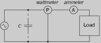
Symbols of electrical devices
For a current to occur, it is necessary to connect two points, one of which has an excess of electrons compared to the other. In other words, it is necessary to create a potential difference between these two points. Just to obtain the potential difference in the circuit, a current source is used.
Important! A load is any consumer of electrical energy. This factor provides resistance to electric current and the magnitude of the current depends on the value of the load resistance. Current flows from the energy source to the load through the conductors. As a cable, you can use materials with the lowest resistance (copper, silver, gold).
Passive and active elements of electrical circuits.
Electric circuit element
called an idealized device that reflects any of the properties of a real electrical circuit.
Electrical circuits in which the parameters of all elements do not depend on the magnitude and directions of currents and voltages, i.e. graphs of current-voltage characteristics (volt-ampere characteristics)
elements are straight lines, called linear.
Accordingly, such elements are called linear
.
When the parameters of the elements of an electrical circuit depend significantly on current or voltage, i.e. The graphs of the current-voltage characteristics of these elements are curvilinear in nature, then such elements are called nonlinear
. If an electrical circuit contains at least one nonlinear element, then it is a nonlinear electrical circuit.
In the theory of electrical circuits, active and passive elements
. The former contribute energy to the electrical circuit, and the latter consume it.
Passive elements of electrical circuits
Resistive resistance is an idealized element of an electrical circuit that has the property of irreversible energy dissipation. A graphical representation of this element and its current-voltage characteristic is shown in the figure (a - nonlinear resistance, b - linear resistance).
The voltage and current across the resistive resistance are interconnected by the dependencies: u = iR, i = Gu. The proportionality coefficients R and G in these formulas are called resistance,
and
conductivity
and are measured in ohms [Ohm] and siemens [Sm]. R = 1/G.
Inductive element
is an idealized element of an electrical circuit that has the property of storing magnetic field energy. A graphic representation of this element is shown in the figure (a - nonlinear, b - linear).
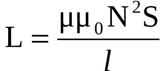
Linear inductance is characterized by a linear relationship between flux linkage ψ and current i, called the Weber-ampere characteristic ψ = Li. Voltage and current are related by the relation u = dψ/dt = L(di/dt)
The proportionality coefficient L in the formula is called inductance and is measured in henry (H).
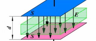
Capacitive element (capacitance)
is an idealized element of an electrical circuit that has the property of accumulating electric field energy. A graphic representation of this element is shown in the figure. (a - nonlinear, b - linear).
Linear capacitance is characterized by a linear relationship between charge and voltage, called the coulomb-volt characteristic
q = Cu
The voltage and current of the capacitor are related by the relations i = dq/dt =C(du/dt).
Active elements of electrical circuits
Active are the circuit elements that release energy into the circuit, i.e. energy sources. There are independent and dependent sources
. Independent sources: voltage source and current source.
Voltage source
- an idealized element of an electrical circuit, the voltage at the terminals of which does not depend on the current flowing through it.
The internal resistance of an ideal voltage source is zero.
Current source
- This is an idealized element of an electrical circuit, the current of which does not depend on the voltage at its terminals.
The internal resistance of an ideal current source is infinity.
Voltage (current) sources are called dependent (controlled)
, if the magnitude of the voltage (current) of the source depends on the voltage or current of another section of the circuit. Dependent sources are used to model vacuum tubes, transistors, and amplifiers operating in linear mode.
Electrical circuit diagram
An electrical circuit, its graphical representation, symbols of its constituent elements, as well as symbols represent a classic diagram of a calculation model. This type is differently accepted as an equivalent equivalent circuit. Where possible, the electrical engineering shown in the electrical circuit diagram shows the entire process. During the calculation, each real element of the circuit is replaced by elements of the circuit.
EC scheme
In conclusion, it should be noted that each element of the circuit, depending on the nature of the connection and electrical properties, can be identified as an energy source or as a consumer. Each section on the EC diagram corresponds to a conductor or a specific device (transformer, rectifier, inverter and other electrical equipment). Only after correctly reading the electrical diagram can a specialist ensure its functionality.
Electrical circuit elements
Every electrical circuit includes various devices and objects that create paths for electrical current to flow.
To describe the electromagnetic processes occurring in each of them, concepts such as electromotive force, current and voltage are used. Conventionally, all elements of the electrical circuit are divided into three components:
- The first is represented by power sources that generate electricity.
- The second is elements that convert electricity into other types of energy. They are better known as receivers.
- The third part consists of transmitting devices - wires and other installations that ensure the level and quality of voltage.
- Electrical circuit diagrams
- Active and passive elements of an electrical circuit
- Symbols of electrical circuit elements
- Three-phase electrical circuits
Fiber-optic communication lines: composition and functions of the main elements
Fiber optic communication lines are very popular today. The main feature of such networks is that with their help it is possible to ensure the transmission of large streams of information at very high speeds.
Optical cross-connects, multiplexers, modulators, etc. – many different elements are included in the network. You need to understand what specific function each of these devices performs.
To begin with, it should be noted that the components of any fiber-optic data transmission network can be divided into passive and active.
Passive elements of fiber-optic communication lines
This category primarily includes optical cable. It consists of several fibers, through which data is actually transmitted. Based on the number of fibers that make up the cable, its capacity is determined.
Another passive element of an optical communication line is the coupling. It is used to connect cables. Another passive element is the optical cross. With its help, the cable is connected to various equipment (including terminal devices from the network).
Very often you can come across such a name as patch-cord. It is used to designate a cable (cord) that is used to connect equipment to each other or to connect it to a transmission network. The patch cord can be of any type, but there is one very important condition - its length should not exceed 5 meters (the exception is the option for open offices according to the TSB-75 standard).
Active elements of fiber-optic communication lines
As for the active elements of fiber-optic communication lines, these include:
- multiplexers and demultiplexers. With the help of these devices, the principle of spectral channel division is implemented, providing high network throughput;
- regenerators, with the help of which the pulse shape is restored at the receiving end of the system;
- lasers. In fiber-optic communication lines they act as sources of radiation, through which information is transmitted;
- modulators. This device ensures that the shape of the carrier wave changes in accordance with the transmitted data. Currently, systems with direct modulation are widespread, where the laser also performs the functions of a modulator;
- amplifiers Using this element, the specified level of signal power is ensured when transmitting over long distances;
- a photodetector with the help of which optoelectronic signal conversion is performed.
It can be seen that the fiber-optic line includes a large number of components. In order for them to function as they should, you should trust the installation of networks to professionals.