The tracks and pads on modern boards are becoming smaller and smaller, and the boards themselves are often multi-layered.
All this greatly complicates the process of disconnecting an element in order to monitor its performance.
Therefore, the question becomes relevant: how to check a capacitor with a multimeter without desoldering it? Let's try to find a solution.
Checking with a multimeter
Using a multimeter, two parameters of the capacitor are checked: internal resistance and capacitance.
Internal resistance (check for breakdown and open circuit)
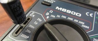
The multimeter is switched to resistance measurement mode by setting the switch in the “Ω” sector to the upper position - for different models this is 2 or 20 MOhm.
Next, touch the probes to the capacitor terminals. If it works, the following happens:
- At first, the multimeter shows low resistance - the capacitor is charged by the voltage supplied to the probes;
- As the charge in the capacitor increases, the resistance gradually increases and eventually reaches a very high value: on the display - a value of over 2 MOhm or “1” (infinity symbol).
Other behavior of the device indicates a malfunction of the element when the resistance:
- it turned out to be below 2 MOhm: the capacitor was broken (conductivity appeared in the dielectric between the plates);
- immediately became infinitely large: output break.
Capacitors are divided into two types: polar and non-polar. The former are sensitive to the polarity of measurements and if it is mixed up by applying a positive potential to the “minus” terminal and a negative potential to the “positive” terminal, they fail. The “negative” terminal is recognized by the o on the capacitor body.
In a multimeter, potentials are distributed as follows:
- port “COM” - negative: according to an unspoken rule, the black probe is included here;
- port “V/ Ω” - positive: it is customary to turn on the red probe.
If there is a known good capacitor of the same brand, the condition of the test item is checked by comparison:
- measure the resistance of a working capacitor;
- the same is done for the element under study;
- compare the rate of change of readings on the multimeter.
An analog (arrow) tester is more suitable for this method: a smoothly deviating arrow clearly reflects the change in resistance in real time.
The capacitor is checked in a discharged state, otherwise electrical injury or damage to the multimeter may occur.
The discharge method depends on the capacity:
- small (low voltage): short-circuit the terminals with a screwdriver;
- large (high voltage): the terminals are closed with a 10 kOhm resistor.
The resistor is held with a tool with insulated handles.
Capacity
Measuring capacitance is possible if the multimeter has a special function. Such devices have a “CX” sector on the front panel.
The capacitor is connected in two ways:
- some models have probe connectors marked “CX”;
- others have two contact pads marked “+” and “-” in the “CX” sector.
When the probes or pads come into contact with the terminals of the capacitor, the capacitance value is displayed on the display. The data obtained is compared with the numerical indicator indicated on the capacitor body, after which a conclusion is drawn about its suitability.
The switch should be installed in the “CX” sector at the position with the nearest higher value in relation to the expected capacitance. Typically there are 5 positions in a sector with data from 20 nF to 200 µF.
This control method is not suitable for capacitors with a capacity of less than 0.25 µF. They are checked with a special device - an LC meter.
In the absence of a capacitance determination function, the capacitor is checked as follows:
- It is charged from a DC source. The source voltage is approximately half the capacitor voltage. For a 25 V element, a 9 - 12 V source is sufficient.
- After waiting a few seconds, which is usually enough to fully charge, the radio component is disconnected from the power supply and the voltage at its terminals is measured with a multimeter.
The meter is configured as follows:
- the black probe is included in the “COM” port;
- red - to the “V/Ω” port;
- switch: to the DC voltage measurement sector (“DCV” or “V-”) to the position with the nearest higher value relative to the expected capacitor voltage.
Replacing a capacitor without desoldering it from the board
Repair conditions vary, and changing a capacitor on a multilayer (PC motherboard, for example) printed circuit board is not the same as changing a capacitor in a power supply (single-layer, single-sided printed circuit board). You must be extremely careful and careful. Unfortunately, not everyone was born with a soldering iron in their hands, and repairing (or trying to repair) something is very necessary.
As I already wrote in the first half of the article, most often the cause of breakdowns is capacitors. Therefore, replacing capacitors is the most common type of repair, at least in my case. Specialized workshops have special equipment for these purposes. If you don’t have it, you have to use conventional equipment (flux, solder and soldering iron). In this case, experience helps a lot.
And if there is no experience, then an attempt at repair may well end in failure. Just for such cases, I hasten to share a method for replacing capacitors without desoldering them from the printed circuit board. The method is outwardly rather inaccurate and to some extent more dangerous than the previous one, but for personal use it will do.
The main advantage of this method is that the contact pads of the board will have to be subjected to much less heat. At least twice. Printing on cheap motherboards quite often peels off due to heat. The tracks come off, and fixing this later is quite problematic.
The disadvantage of this method is that you still have to put pressure on the board, which can also lead to negative consequences. Although from my personal experience I have never had to press hard. In this case, there is every chance of soldering to the legs remaining after mechanical removal of the capacitor.
So, replacing a capacitor begins with removing the damaged part from the motherboard.
You need to place your finger on the capacitor and, with light pressure, try to swing it up and down and left and right. If the capacitor swings left and right, then the legs are located along the vertical axis (as in the photo), otherwise along the horizontal axis. You can also determine the position of the legs by the negative marker (a strip on the capacitor body indicating the negative contact).
Next, you should press the capacitor along the axis of its legs, but not sharply, but smoothly, slowly increasing the load. As a result, the leg is separated from the body, then we repeat the procedure for the second leg (press from the opposite side).
Sometimes the leg is pulled out along with the capacitor due to bad solder. In this case, you can slightly widen the resulting hole (I do this with a piece of guitar string) and insert a piece of copper wire there, preferably the same thickness as the leg.
Half the job is done, now we move directly to replacing the capacitor. It is worth noting that the solder does not stick well to the part of the leg that was inside the capacitor body and it is better to bite it off with wire cutters, leaving a small part. Then the legs of the capacitor prepared for replacement and the legs of the old capacitor are treated with solder and soldered. It is most convenient to solder the capacitor by placing it on the board at an angle of 45 degrees. Then you can easily stand him at attention.
The resulting appearance is, of course, unaesthetic, but it works and this method is much simpler and safer than the previous one in terms of heating the board with a soldering iron. Happy renovation!
It is believed that about half of the failures of electronic boards are associated with a malfunction of the capacitor, without replacing which the further functioning of the circuit is impossible.
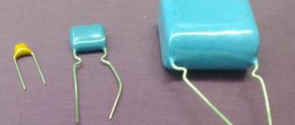
These parts themselves may vary both in characteristics and dimensions; however, they all have one thing in common - the presence of the main controlled parameter (capacity).
In order to check the capacitor installed in the circuit (including the so-called “electrolytes”), it is necessary to measure its capacitance. The faulty part will have to be removed from the circuit and then soldered on with a new one. Some types of capacitors do not need to be soldered, since they are attached by welding or clamps.
How to check without desoldering
To check without dismantling, special testers are used. They differ from conventional ones by lower voltage on the probes, which minimizes the risk of damage to other circuit components.
If such a device is not available, you can turn a regular multimeter into it by connecting it through an attachment. Various schemes of such set-top boxes have been published on the Internet and in specialized magazines.
Regardless of which device is used to measure the parameters of the capacitor, the question of the influence of other elements remains relevant. So, if several more capacitors are connected to the circuit in parallel with the one being tested, the tester will show their total capacitance.
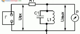
How to use a multimeter
Parallel inclusion of a working component in the circuit
Another way to check a capacitor without desoldering is to connect a known-good analogue of the same capacitance in parallel with it. If the device works, then the problem really was in the capacitor and it needs to be replaced.
This test method cannot be used in high voltage circuits.
Checking for spark
If you don’t have a measuring device at hand or if the capacitor capacity is large, you can check it “by eye”.
The element is charged, then a metal tool with insulated handles is used to short-circuit its terminals. You should wear rubber gloves on your hands.
A bright spark accompanied by a characteristic sound indicates the serviceability of the capacitor. If the discharge turns out to be sluggish, it is time to dispose of the radio component.
To obtain comprehensive information about the condition of the capacitor, you need a multimeter with a capacitance measurement function (there is a “CX” sector on the control panel).
But even a tester not equipped with such an option will tell a lot about this element. Removing the capacitor from the board is not always necessary, but you should be prepared for the fact that when taking measurements on the board, the accuracy will be far from ideal.
The tracks and pads on modern boards are becoming smaller and smaller, and the boards themselves are often multi-layered.
All this greatly complicates the process of disconnecting an element in order to monitor its performance.
Therefore, the question becomes relevant: how to check a capacitor with a multimeter without desoldering it? Let's try to find a solution.
How to choose the right capacitor
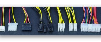
Each capacitor is marked. There are 4 parameters specified there:
- voltage in volts,
- capacity in microfarads,
- working temperature,
- polarity marking.
Capacitors may vary in size, but this has virtually no effect. You can use capacitors with a higher volume of microfarads (but it is not recommended to use capacitors with a reduced electrical capacity).
As for the polarity markings on the capacitor, the minus is marked with a gray or gold stripe. On the part being repaired (in my case, the motherboard), the polarity is indicated in the form of a two-color circle, cut in half. The shaded part of the circle is a minus. The capacitor is placed on the board minus to minus, plus to plus.
The only exception is Asus boards. Their polarity markings are reversed, i.e. their filled semicircle is a plus. It is on the Asus motherboard that we will be replacing capacitors today.
We need to determine which capacitors are swollen or burst. I had to break down the Conder for demonstration. True swollen capacitors look a little different, but hopefully you get the idea.
We should also find this capacitor on the back of the board.
So, we have identified a capacitor for replacement on both sides of the motherboard. Now you can start soldering.
Checking with a multimeter
Using a multimeter, two parameters of the capacitor are checked: internal resistance and capacitance.
Internal resistance (check for breakdown and open circuit)
The multimeter is switched to resistance measurement mode by setting the switch in the “Ω” sector to the upper position - for different models this is 2 or 20 MOhm.
Next, touch the probes to the capacitor terminals. If it works, the following happens:
- At first, the multimeter shows low resistance - the capacitor is charged by the voltage supplied to the probes;
- As the charge in the capacitor increases, the resistance gradually increases and eventually reaches a very high value: on the display - a value of over 2 MOhm or “1” (infinity symbol).
Other behavior of the device indicates a malfunction of the element when the resistance:
- it turned out to be below 2 MOhm: the capacitor was broken (conductivity appeared in the dielectric between the plates);
- immediately became infinitely large: output break.
Capacitors are divided into two types: polar and non-polar. The former are sensitive to the polarity of measurements and if it is mixed up by applying a positive potential to the “minus” terminal and a negative potential to the “positive” terminal, they fail. The “negative” terminal is recognized by the o on the capacitor body.
In a multimeter, potentials are distributed as follows:
- port “COM” - negative: according to an unspoken rule, the black probe is included here;
- port “V/ Ω” - positive: it is customary to turn on the red probe.
If there is a known good capacitor of the same brand, the condition of the test item is checked by comparison:
- measure the resistance of a working capacitor;
- the same is done for the element under study;
- compare the rate of change of readings on the multimeter.
An analog (arrow) tester is more suitable for this method: a smoothly deviating arrow clearly reflects the change in resistance in real time.
The capacitor is checked in a discharged state, otherwise electrical injury or damage to the multimeter may occur.
The discharge method depends on the capacity:
- small (low voltage): short-circuit the terminals with a screwdriver;
- large (high voltage): the terminals are closed with a 10 kOhm resistor.
The resistor is held with a tool with insulated handles.
Capacity
Measuring capacitance is possible if the multimeter has a special function. Such devices have a “CX” sector on the front panel.
The capacitor is connected in two ways:
- some models have probe connectors marked “CX”;
- others have two contact pads marked “+” and “-” in the “CX” sector.
When the probes or pads come into contact with the terminals of the capacitor, the capacitance value is displayed on the display. The data obtained is compared with the numerical indicator indicated on the capacitor body, after which a conclusion is drawn about its suitability.
The switch should be installed in the “CX” sector at the position with the nearest higher value in relation to the expected capacitance. Typically there are 5 positions in a sector with data from 20 nF to 200 µF.
This control method is not suitable for capacitors with a capacity of less than 0.25 µF. They are checked with a special device - an LC meter.
In the absence of a capacitance determination function, the capacitor is checked as follows:
- It is charged from a DC source. The source voltage is approximately half the capacitor voltage. For a 25 V element, a 9 - 12 V source is sufficient.
- After waiting a few seconds, which is usually enough to fully charge, the radio component is disconnected from the power supply and the voltage at its terminals is measured with a multimeter.
The meter is configured as follows:
- the black probe is included in the “COM” port;
- red - to the “V/Ω” port;
- switch: to the DC voltage measurement sector (“DCV” or “V-”) to the position with the nearest higher value relative to the expected capacitor voltage.
How to check without desoldering
To check without dismantling, special testers are used. They differ from conventional ones by lower voltage on the probes, which minimizes the risk of damage to other circuit components.
If such a device is not available, you can turn a regular multimeter into it by connecting it through an attachment. Various schemes of such set-top boxes have been published on the Internet and in specialized magazines.
Regardless of which device is used to measure the parameters of the capacitor, the question of the influence of other elements remains relevant. So, if several more capacitors are connected to the circuit in parallel with the one being tested, the tester will show their total capacitance.
How to use a multimeter
Parallel inclusion of a working component in the circuit
Another way to check a capacitor without desoldering is to connect a known-good analogue of the same capacitance in parallel with it. If the device works, then the problem really was in the capacitor and it needs to be replaced.
This test method cannot be used in high voltage circuits.
Checking for spark
If you don’t have a measuring device at hand or if the capacitor capacity is large, you can check it “by eye”.
The element is charged, then a metal tool with insulated handles is used to short-circuit its terminals. You should wear rubber gloves on your hands.
A bright spark accompanied by a characteristic sound indicates the serviceability of the capacitor. If the discharge turns out to be sluggish, it is time to dispose of the radio component.
To obtain comprehensive information about the condition of the capacitor, you need a multimeter with a capacitance measurement function (there is a “CX” sector on the control panel).
But even a tester not equipped with such an option will tell a lot about this element. Removing the capacitor from the board is not always necessary, but you should be prepared for the fact that when taking measurements on the board, the accuracy will be far from ideal.
It's been about a year and a half since I started doing electronics repairs regularly. As it turned out, this matter is no less interesting than the design of electronic structures. Little by little people appeared who wanted, some from time to time and some regularly, to collaborate with me as a master. Due to the fact that the profitability of most of the repairs carried out does not allow renting premises, otherwise rent eats up most of the profit, I work mainly at home or go with tools to familiar individual entrepreneurs who buy consumer electronics and have a workshop.
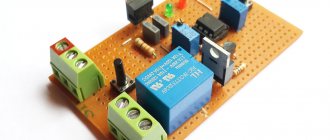
In parallel with a friend, we buy equipment on the local forum and Avito, repair it and the friend sells it, both in shares of the sale. But that's not the point. Today I decided to share with readers a diagram of a simple, but very useful for any electronics repairman, ESR meter, which allows you to correctly measure this parameter, in most cases, without soldering the electrolytic capacitors. ESR, also known as ESR (Equivalent Series Resistance) is a capacitor parameter that greatly influences its performance when operating in high-frequency circuits. What kind of devices are these?
These are absolutely any circuits using stabilizers, DC-DC power converters, switching power supplies for any equipment, from computers to mobile chargers.
Without this device, a significant part of the repairs I performed either could not have been performed at all, or was still performed, but with great inconvenience in the form of constant soldering and soldering back electrolytic capacitors of small value, in order to measure the equivalent series resistance using a transistor tester. My device allows you to measure this parameter without desoldering the part, simply by touching the terminals of the capacitor with tweezers.
These capacitors with a nominal value of 0.33-22 uF, as is known, very rarely have notches in the upper part of the case, along which capacitors of a higher nominal value swell and open like a rose, for example, the familiar capacitors on motherboards and power supplies. The fact is that a capacitor that does not have these notches to release the excess pressure generated is visually, without measuring with a device, even for an experienced electronics engineer, in no way distinguishable from a fully working one.
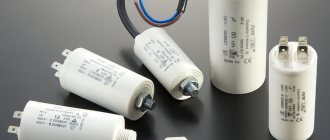
Computer power supply
Of course, if a home craftsman needs a one-time repair, for example, an ATX computer power supply, there is no point in assembling this device; it is easier to immediately replace all the small capacitors with new ones, but if you repair at least five power supplies every six months, this device is already desirable for you assembly. What alternatives are there to assembling this meter? A purchased device that costs about 2000 rubles, ESR micro.
ESR micro – photo
Of the differences and advantages of a purchased device, I can only name that its readings are displayed immediately in milliOhms, while my device needs to be converted from milliVolts to milliOhms. Which, however, does not cause any difficulties, it is enough to calibrate the device using the values of low-resistance precision resistors and create a table for yourself. After working with the device for a couple of months, visually, without any tables, just by looking at the display of the multimeter you can already see the normal value of the ESR of the capacitor - on the verge or replacement is already necessary. The diagram of my device, by the way, was once taken from Radio magazine.
My experience replacing capacitors on a motherboard
Hello! I want to share with you my experience of replacing capacitors on a motherboard. This can hardly be called a guide, much less a master class, since I solder rarely and crookedly, but let’s see what happened. ))
It's no secret that the motherboard is one of the key elements of a computer. It is what unites all the components of the system into a single whole. Its failure always causes a lot of trouble. It’s good if you just need to replace the board itself, but if it’s outdated, then you often have to change a good half of the components (processor, cooler, RAM, etc.).
Therefore, many users first want to try to repair the old motherboard to avoid unnecessary costs.
One of the common causes of motherboard breakdowns is “swelling” of capacitors. Capacitors can fail due to power fluctuations, high temperatures, and simply from old age.
Enough theory, it's time to move on to practice.
I used the following tools:
- Soldering iron;
- Rosin;
- Solder;
- Toothpicks;
- Purified gasoline (to remove rosin from the board).
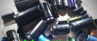
It is quite easy to identify swollen capacitors if you look closely at the board. They may have traces of leaked electrolyte, and they may also bend at the top or bottom, which will also be clearly visible.
This is what a swollen conder looks like.
First of all, you need to find new spare parts of a suitable value. We look carefully at the markings. In my case it is 6.3 volts 1500 uF. As a replacement, I used 16 volts 1500 uF. You can take capacitors of higher capacity and higher voltage, but you need to take into account that the higher the voltage and capacity, the larger its size (it may simply not fit in the same place).
Since it was evening and the shops were not open, I had to remove the required capacitor from the non-working motherboard.
Ideally, to desolder such parts you need to use a desoldering pump or a soldering hair dryer. Since I only have a soldering iron at home, I had to desolder it, alternately heating the legs of the capacitor and pulling it out. Conclusion: doing this with a simple soldering iron is extremely inconvenient.
After we have removed the old capacitor and prepared a replacement for it, we need to clean the holes for the capacitor, otherwise the old solder will not allow it to be inserted properly. The desalination pump could have been done in a couple of seconds, but I had to fiddle around and use toothpicks. Carefully insert them into the holes and heat them with a soldering iron from the back to push out all the excess solder. I repeat once again that this must be done carefully, since the board is multi-layered and the tracks inside the board can be damaged.
The best part remains.
After cleaning the holes, insert the capacitor into place, being sure to observe the polarity. Usually, on the motherboard there are markings for installing capacitors (the shaded side is the minus “—”), but it’s best to remember how the old one was installed. On the capacitors themselves there are also symbols in the form of a strip with the sign “-“.
We seal it on the reverse side. I don’t have a photo of the process itself, since I couldn’t solder and take pictures at the same time. But there is a photo of the final result)
Don't forget to clean the board from flux or rosin.
Well, that's it, my repair is over. The main thing is not to be afraid and carefully try to solder with your own hands. I must say, this is a very exciting process.
Schematic diagram of the device
Initially, the device was assembled with homemade probes - tweezers with wide jaws, inconvenient when measuring on boards, with tight installation. Then I looked at express probes on Ali - tweezers for measuring SMD, connected to a multimeter. Having ordered tweezers, the wire was mercilessly shortened so that the accuracy would not be greatly affected during the measurement due to the length of the probe wires. Don't forget, the count is in milliOhms.
At first, my device was connected with probes to a multimeter and was made in the form of an attachment, but gradually I got tired of turning the multimeter knob every time, thereby exhausting the switching life. It was then that a friend of mine gave me a multimeter, due to the fact that I temporarily burned mine on an undischarged electrolytic capacitor. Subsequently, the device was restored, the resistors were re-soldered, and this multimeter, its connectors for connecting the probes on the board were broken off, and jumpers were thrown by someone, but the accuracy of the measurements was no longer the same.
ESR meter open case
But for my purposes, an error of 1-2 percent did not solve anything, and I decided to make the device completely autonomous. To do this, I fastened the case of the multimeter and the case of the ESR meter with screws, and for greater convenience, switched the simultaneous switching of the built-in multimeter and the ESR meter using a switch into two groups of contacts. Connections between the multimeter and the ESR meter, previously made using probes, were made by wires inside connected housings.
Capacitor tester - appearance
As practice has shown, the time required to bring the device into combat readiness, and then, after taking measurements, to turn it off, began to take significantly less time, and the ease of use has accordingly increased. Among the further improvements planned for this device is to switch it to battery power, from a Li-ion battery from a phone, with the ability to recharge from a charge adapter board via a built-in Mini USB socket, from any charger from a smartphone with the ability to connect a USB cable.
As practice has shown, I had previously converted the T4 transistor tester to battery power using a similar method, which, like the ESR meter, also has high consumption due to the graphic display installed in it. Feelings from the remodel were only positive. I only charged it once in six months. The device was equipped with a step-up DC-DC converter that converts 3.7 volts at the battery output into 9 volts, necessary for the operation of the device.
ESR meter development board
In this case, my device will have a double voltage conversion: first from 3.7 volts to 9 volts, although I may also set the minimum voltage allowed for the input of the 7805 CV stabilizer to 7.5 volts; the device circuit is now powered from this stabilizer. The device itself, as can be seen in the photo, is initially powered by a Krohn battery, which, as is known, has a relatively small capacity.
The supply voltage of this microcircuit allows it to be powered directly from 9 volts, but the fact is that as the battery discharges, I noticed that the measurement readings begin to slowly float away. To combat this, a 7805 stabilizer was installed, which, as you know, produces a stable 5 volt output.
Switch with protection against accidental activation
Also, due to the fact that you often have to carry the device with you in a briefcase, for repairs on the road, and there have already been cases of spontaneous switching on of the switch, and accordingly the Krona battery dropped to zero, which now, when switching with this switch, 2 power lines, a multimeter and the device itself would be no longer desirable, since in this case, you would have to buy two crowns, costing 45 rubles.
Switching with a switch for 2 groups of contacts
It was decided to simply glue two self-tapping screws from the cooler mount in the computer power supply to the edges of the switch using hot-melt adhesive. The microcircuit used in the device is widespread and quite cheap; I purchased it for only about 15-20 rubles.
The whole device cost me, taking into account the free multimeter, probes - tweezers from Ali Express, costing 100 rubles, and the cost of parts for assembling the device, and the Krona battery, in total it took about 150 rubles, in total everything needed cost a ridiculous amount of 250 rubles.
Tweezers for measuring capacitors on a board
Which has already paid off with the use of the device in repairs for a long time and many times. Of course, someone who has the opportunity and desire to purchase an ESR micro can now say why I need these inconveniences, every time converting from milliVolts to milliOhms, although this is not required, as I wrote above, if I can immediately see on the purchased device , ready-made values.
ESR Value Table
The fact is that such devices incorporate a microcontroller, and during measurement they are connected directly, so to speak, by the “port” of the microcontroller to the capacitor being measured. What is extremely undesirable, it is enough not to discharge the capacitor once after de-energizing the circuit before measurement, by shorting its terminals with a metal object, for example a screwdriver, as we risk getting a non-working device.
Replacing a capacitor without desoldering it from the board
Repair conditions vary, and changing a capacitor on a multilayer (PC motherboard, for example) printed circuit board is not the same as changing a capacitor in a power supply (single-layer, single-sided printed circuit board). You must be extremely careful and careful. Unfortunately, not everyone was born with a soldering iron in their hands, and repairing (or trying to repair) something is very necessary.
As I already wrote in the first half of the article, most often the cause of breakdowns is capacitors. Therefore, replacing capacitors is the most common type of repair, at least in my case. Specialized workshops have special equipment for these purposes. If you don’t have it, you have to use conventional equipment (flux, solder and soldering iron). In this case, experience helps a lot.
And if there is no experience, then an attempt at repair may well end in failure. Just for such cases, I hasten to share a method for replacing capacitors without desoldering them from the printed circuit board. The method is outwardly rather inaccurate and to some extent more dangerous than the previous one, but for personal use it will do.
The main advantage of this method is that the contact pads of the board will have to be subjected to much less heat. At least twice. Printing on cheap motherboards quite often peels off due to heat. The tracks come off, and fixing this later is quite problematic.
The disadvantage of this method is that you still have to put pressure on the board, which can also lead to negative consequences. Although from my personal experience I have never had to press hard. In this case, there is every chance of soldering to the legs remaining after mechanical removal of the capacitor.
So, replacing a capacitor begins with removing the damaged part from the motherboard.
You need to place your finger on the capacitor and, with light pressure, try to swing it up and down and left and right. If the capacitor swings left and right, then the legs are located along the vertical axis (as in the photo), otherwise along the horizontal axis. You can also determine the position of the legs by the negative marker (a strip on the capacitor body indicating the negative contact).
Next, you should press the capacitor along the axis of its legs, but not sharply, but smoothly, slowly increasing the load. As a result, the leg is separated from the body, then we repeat the procedure for the second leg (press from the opposite side).
Sometimes the leg is pulled out along with the capacitor due to bad solder. In this case, you can slightly widen the resulting hole (I do this with a piece of guitar string) and insert a piece of copper wire there, preferably the same thickness as the leg.
Half the job is done, now we move directly to replacing the capacitor. It is worth noting that the solder does not stick well to the part of the leg that was inside the capacitor body and it is better to bite it off with wire cutters, leaving a small part. Then the legs of the capacitor prepared for replacement and the legs of the old capacitor are treated with solder and soldered. It is most convenient to solder the capacitor by placing it on the board at an angle of 45 degrees. Then you can easily stand him at attention.
The resulting appearance is, of course, unaesthetic, but it works and this method is much simpler and safer than the previous one in terms of heating the board with a soldering iron. Happy renovation!
In the element base of a computer (and not only) there is one bottleneck - electrolytic capacitors. They contain an electrolyte; the electrolyte is a liquid. Therefore, heating such a capacitor leads to its failure, as the electrolyte evaporates. And heating in the system unit is a regular occurrence.
Therefore, replacing capacitors is a matter of time. More than half of the failures of motherboards in the middle and lower price categories are due to dry or swollen capacitors. Even more often, computer power supplies break down for this reason.
Since the printing on modern boards is very dense, replacing capacitors must be done very carefully. You can damage and not notice a small unframed element or break (short) tracks, the thickness and distance between which is slightly greater than the thickness of a human hair. It’s quite difficult to fix something like this later. So be careful.
So, to replace capacitors you will need a soldering iron with a thin tip with a power of 25-30 W, a piece of thick guitar string or a thick needle, soldering flux or rosin.
If you reverse the polarity when replacing an electrolytic capacitor or install a capacitor with a low voltage rating, it may well explode. And here's what it looks like:
So, carefully select the replacement part and install it correctly. Electrolytic capacitors are always marked with a negative terminal (usually a vertical stripe of a different color from the body color). On the printed circuit board, the hole for the negative contact is also marked (usually with black shading or solid white). The ratings are written on the capacitor body. There are several of them: voltage, capacity, tolerances and temperature.
The first two are always present, the others may be absent. Voltage: 16V (16 volts). Capacitance: 220µF (220 microfarads). These values are very important when replacing. The voltage can be chosen equal or with a higher nominal value. But the capacitance affects the charging/discharging time of the capacitor and in some cases can be important for a section of the circuit.
Therefore, the capacity should be selected equal to that indicated on the case. On the left in the photo below is a green swollen (or leaking) capacitor. In general, there are constant problems with these green capacitors. The most common candidates for replacement. On the right is a working capacitor, which we will solder.
The capacitor is soldered as follows: first find the legs of the capacitor on the back side of the board (for me this is the most difficult moment). Then heat one of the legs and lightly press the capacitor body from the side of the heated leg. When the solder melts, the capacitor tilts. Carry out a similar procedure with the second leg. Usually the capacitor is removed in two steps.
There is no need to rush, and there is no need to press too hard. The motherboard is not a double-sided PCB, but a multilayer one (imagine a wafer). Overdoing it can damage the contacts on the inner layers of the printed circuit board. So no fanaticism. By the way, long-term heating can also damage the board, for example, lead to peeling or tearing of the contact pad. Therefore, there is no need to press hard with a soldering iron either. We lean the soldering iron and press lightly on the capacitor.
After removing the damaged capacitor, it is necessary to make holes so that the new capacitor can be inserted freely or with little effort. For these purposes, I use a guitar string of the same thickness as the legs of the part being soldered. A sewing needle is also suitable for these purposes, but needles are now made of ordinary iron, and strings are made of steel. There is a chance that the needle will get caught in the solder and break when you try to pull it out. And the string is quite flexible and steel and solder adhere much worse than iron.
When removing capacitors, solder most often clogs the holes in the board. If you try to solder the capacitor in the same way that I advised you to solder it, you can damage the contact pad and the track leading to it. Not the end of the world, but a very undesirable occurrence. Therefore, if the holes are not clogged with solder, they simply need to be expanded. And if you do, then you need to press the end of the string or needle tightly to the hole, and on the other side of the board, lean the soldering iron against this hole. If this option is inconvenient, then the soldering iron tip should be leaned against the string almost at the base. When the solder melts, the string will fit into the hole. At this moment you need to rotate it so that it does not grab the solder.
After obtaining and expanding the hole, it is necessary to remove excess solder from its edges, if any, otherwise, during soldering of the capacitor, a tin cap may form, which can solder adjacent tracks in those places where the seal is dense. Pay attention to the photo below - how close the tracks are to the holes. Soldering this is very easy, but difficult to notice, since the installed capacitor interferes with the view. Therefore, it is very advisable to remove excess solder.
If you don’t have a radio market nearby, then most likely you can only find a used capacitor for replacement. Before installation, its legs should be treated, if necessary. It is advisable to remove all solder from the legs. I usually coat the legs with flux and tin them with a clean soldering iron tip, the solder collects on the soldering iron tip. Then I scrape the legs of the capacitor with a utility knife (just in case).
That's all, actually. We insert the capacitor, lubricate the legs with flux and solder. By the way, if you use pine rosin, it is better to crush it into powder and apply it to the installation site than to dip a soldering iron in a piece of rosin. Then it will work out neatly.
First version of the probes
Which, given its rather high cost, you will agree, is not the best option. In my device, a 100 Ohm resistor is connected in parallel to the capacitor being measured, which means that if the capacitor is nevertheless charged, it will begin to discharge when the probes are connected. In the worst case scenario, if the microcircuit used in my device burns out, to make repairs you will only need to remove the microcircuit from the DIP socket and plug in a new one.