Natural grounding agent: what can be used
Standardization of the use of grounding conductors in electrical installations of buildings is regulated in the following documentation:
- PUE 7th edition Section 1 Chapter 1.7.
- GOST R 50571.21-2000 (IEC 60364-5-548-96).
- GOST R 50571.22-2000 (IEC 60364-7-707-84).
- GOST R 50571.10-96 (IEC 364-5-54-80).
The main requirement when using a natural circuit is its resistance to flowing short circuit currents. The possibility of a possible malfunction of devices associated with grounding electrodes is excluded.
A natural grounding system involves the construction of a structure that is permanently located in the ground. The following are commonly used as grounding devices of this type:
- Metal or reinforced concrete structure (rebar, reinforced concrete foundations of objects in contact with the soil).
- Metal water pipes running underground.
- Casing type borehole pipes.
- Metal piles (tongues) of hydraulic structures.
- Sheaths of metallic composition of various armored cables running underground.
- Railway tracks of non-electrified roads with the mandatory presence of jumpers.
Compliance with the requirements of the PUE for the conductivity cross-section ratio is a generally mandatory aspect of choosing any device as a grounding element. The natural ground electrode is connected to the grounding main of the electrical installation in two or more places.
It is prohibited to use the following as a natural contour:
- Designs of metal pipes containing flammable or toxic substances and gases.
- Pipes with corrosion-resistant insulation.
- Conductors of heating systems or sewer lines.
Natural grounding is used everywhere - only if it is necessary to reduce the potentials of currents flowing through it that go into the ground, artificial grounding devices are used.
Grounding
In Russia, grounding requirements and its arrangement are regulated by the Electrical Installation Rules (PUE).
Grounding in electrical engineering is divided into natural and artificial.
Natural grounding
It is customary to refer to natural grounding as those structures, the structure of which provides for a permanent presence in the ground. However, since their resistance is not regulated in any way and no requirements are imposed on the value of their resistance, natural grounding structures cannot be used as grounding for an electrical installation. Natural grounding conductors include, for example, the reinforced concrete foundation of a building.
Artificial grounding
Grounding a section of a contact network during repair work
Artificial grounding is a deliberate electrical connection of any point in the electrical network, electrical installation or equipment with a grounding device.
Grounding device
(GD) consists of a ground electrode (a conductive part or a set of interconnected conductive parts that are in electrical contact with the ground directly or through an intermediate conducting medium) and a grounding conductor connecting the grounded part (point) to the ground electrode. The ground electrode can be a simple metal rod (most often steel, less often copper) or a complex set of specially shaped elements.
The quality of grounding is determined by the value of grounding resistance/resistance to current spreading (the lower, the better), which can be reduced by increasing the area of the grounding electrodes and reducing the electrical resistivity of the soil: increasing the number of grounding electrodes and/or their depth; increasing the concentration of salts in the soil, heating it, etc.
The electrical resistance of the grounding device is different for different conditions and is determined / standardized by the requirements of the PUE and relevant standards.
Types of artificial grounding systems
Types of grounding systems for electrical networks
Electrical installations with regard to electrical safety measures are divided into:
- electrical installations with voltages above 1 kV in networks with a solidly grounded or effectively grounded neutral;
- electrical installations with voltages above 1 kV in networks with an isolated neutral or grounded through an arc suppression reactor or resistor;
- electrical installations with voltage up to 1 kV in networks with a solidly grounded neutral;
- electrical installations with voltage up to 1 kV in networks with an insulated neutral.
Depending on the technical features of the electrical installation and supply networks, its operation may require different grounding systems. As a rule, before designing an electrical installation, the sales organization issues a list of technical conditions that stipulate the grounding system used.
The classification of types of grounding systems is given as the main characteristics of the supply electrical network. GOST R 50571.2-94 “Electrical installations of buildings. Part 3. Main characteristics"
regulates the following grounding systems:
TN-C
,
TN-S
,
TN-CS
,
TT
,
IT
.
For electrical installations with voltage up to 1 kV, the following designations are accepted:
- TN
system - a system in which the neutral of the power source is solidly grounded, and the open conductive parts of the electrical installation are connected to the solidly grounded neutral of the source through neutral protective conductors; - TN-C
system -
TN
, in which the neutral protective and neutral working conductors are combined in one conductor along its entire length; - TN-S
system -
TN
, in which the neutral protective and neutral working conductors are separated along its entire length; - TN-CS
system -
TN
, in which the functions of the neutral protective and neutral working conductors are combined in one conductor in some part of it, starting from the power source; - IT
system - a system in which the neutral of the power source is isolated from the ground or grounded through devices or devices having high resistance, and the exposed conductive parts of the electrical installation are grounded; - TT
system - a system in which the neutral of the power source is solidly grounded, and the exposed conductive parts of the electrical installation are grounded using a grounding device that is electrically independent of the solidly grounded neutral of the source.
The first letter is the state of the neutral of the power source relative to ground
- T
- grounded neutral (lat. terra); - I
- isolated neutral (English isolation).
The second letter is the state of exposed conductive parts relative to ground
- T
- open conductive parts are grounded, regardless of the relation to the ground of the neutral of the power source or any point of the supply network; - N
- open conductive parts are connected to the solidly grounded neutral of the power source.
Subsequent (after N) letters - combination in one conductor or separation of the functions of the zero working and zero protective conductors
- S
- zero working (
N
) and zero protective (PE) conductors are separated; - C
- the functions of the neutral protective and neutral working conductors are combined in one conductor (PEN conductor) (combined); - N
- zero working (neutral) conductor; (English neutral) - PE
- protective conductor (grounding conductor, neutral protective conductor, protective conductor of the potential equalization system) (English: Protective Earth) - PEN
- combined zero protective and zero working conductors (English: Protective Earth and Neutral).
Systems with solidly grounded neutral (TN systems)
Systems with a solidly grounded neutral are usually called TN
-systems, since this abbreviation comes from the French. Terre-Neutre, which means "ground-neutral".
| Schematic diagram of the TN-S | Schematic diagram of the TN-C | Schematic diagram of the TN-CS |
- Separating zeros in TN-S and TN-CS
TN-C system
TN-C system
(French Terre-Neutre-Combiné) was proposed by the German concern AEG in 1913 [
source not specified 249 days
].
The working zero and PE
conductor (Protection Earth) in this system are combined into one wire.
The biggest drawback was the possibility of linear voltage appearing on the housings of electrical installations in the event of an emergency zero
. Despite this, this system is still found in buildings in the countries of the former USSR. Of modern electrical installations, such a system is found only in street lighting for reasons of economy and reduced risk.
TN-S system
TN-S system
(French: Terre-Neutre-Séparé) was developed to replace the conventionally dangerous
TN-C
in the 1930s. The working and protective zeros were separated directly at the substation, and the ground electrode was a rather complex structure of metal fittings. Thus, when the working zero was broken in the middle of the line, the electrical installation housings did not receive line voltage. Later, such a grounding system made it possible to develop differential circuit breakers and current leakage circuit breakers capable of sensing small currents. Their work is based on Kirchhoff's rules, according to which the current flowing through the working zero must be numerically equal to the geometric sum of the currents in the phases.
TN-CS system
In TN-CS
The transformer substation has a direct connection of the current-carrying parts to the ground and a tightly grounded neutral. To ensure communication between the transformer substation and the entrance to the building, a combined neutral conductor (N) and a protective conductor (PE), designated PEN, are used. When entering the building, it (PEN) is divided into a separate neutral (N) and protective conductor (PE).
- You can also observe the TN-CS
, where the separation of zeros occurs in the middle of the line, however, if the neutral wire breaks before the separation point, the housings will be under line voltage, which will pose a threat to life if touched. - Advantages: a simpler lightning protection device (it is impossible for a voltage peak to occur between PE
and
N
), the ability to protect against phase short circuits on the device body using ordinary “automatic devices”. - Disadvantages: extremely poor protection against “zero burnout”, that is, destruction of PEN
on the way from the transformer substation to the separation point.
In this case, phase voltage appears on the PE
on the consumer side, which cannot be turned off by any automation (
PE
cannot be turned off).
If inside a building the potential equalization system (EPS) serves as protection from this (everything metal is energized, and there is no risk of electric shock when touching 2 different objects), then in the open air there is no protection from this at all [ source not specified 1294 days
].
In accordance with the PUE, this is the main and recommended system, but at the same time, the PUE requires compliance with a number of measures to prevent the destruction of PEN
- mechanical protection
PEN
, as well as repeated grounding
of PEN
overhead lines along poles over a certain distance (no more than 200 meters for areas with the number of thunderstorm hours per year up to 40, 100 meters for areas with the number of thunderstorm hours per year more than 40).
In cases where it is impossible to comply with these measures, the PUE recommends TT
.
TT
also recommended for all outdoor installations (sheds, verandas, etc.)
In city buildings with PEN
usually a thick metal frame that runs vertically through the entire building.
TN-CS
is used in urban buildings .
In rural areas in Russia, in practice, there are a huge number of overhead lines without mechanical protection PEN
and repeated groundings.
TT
system is more popular in rural areas .
, TN-CS was usually used
with a division point based on the electrical panel (
PEN
) next to the meter, while
PE
was carried out only for the electric stove.
In modern Russian buildings, a “five-wire system” is also used with a division point in the basement; independent Ns
and
P.E.
_
TT system
- Schematic diagram of the TT system
In TT
The transformer substation has a direct connection of current-carrying parts to the ground. All open conductive parts of the building's electrical installation have a direct connection to the ground through a ground electrode, electrically independent from the neutral ground electrode of the transformer substation.
- Advantages: high resistance to N
on the way from the transformer substation to the consumer.
This destruction has no effect on PE
. - Disadvantages: requirements for more complex lightning protection (the possibility of a peak appearing between N
and
PE
), as well as the inability for a conventional circuit breaker to trace a phase short circuit to the device body (and further to
PE
). This is due to a fairly noticeable (30-40 Ohm) resistance of the local grounding.
Due to the above, the PUE recommends TT
only as an "additional" system (provided the supply line does not satisfy the
TN-CS
for re-earthing and mechanical protection
PEN
), and in outdoor installations where there is a risk of simultaneous contact with the installation and physical earth (or physically grounded metal elements).
However, due to the poor quality of most air lines in rural Russia, the TT
extremely popular there.
TT
requires the mandatory use of an RCD.
Typically, an introductory RCD is installed with a setting of 300-100 mA, which monitors short circuits between the phase and PE
, followed by personal RCDs for specific circuits at 30-10 mA to protect people from electric shock.
Lightning protection devices such as ABB OVR
, differ in design for
TN-C-
S and
TT
, the latter having a gas arrester between
N
and
PE
and varistors between
N
and the phases.
Isolated Neutral Systems
IT system
- Isolated Neutral Systems
- Schematic diagram of an IT system
In the IT
The neutral of the power supply is isolated from ground or grounded through instruments or devices having high resistance, and exposed conductive parts are grounded. The leakage current to the housing or to ground in such a system will be low and will not affect the operating conditions of the connected equipment.
IT system
used, as a rule, in electrical installations of buildings and structures for special purposes, which are subject to increased reliability and safety requirements, for example, electrical installations of underground mines and coal mines, while at the same time to create safe operating conditions for operating personnel (when potential appears at the electrical installation relative to the ground) and to avoid explosions of dust and gases, so-called mine protection devices against leakage currents are mandatory;
IT
system can also be used in hospitals for emergency power supply and lighting.
Portable gasoline and diesel power stations have an isolated neutral, which makes it possible to use electrical appliances connected to them quite safely without grounding, which is problematic to do in “field” conditions.
Previously, a system with an isolated neutral was widespread in the power supply systems of residential buildings, especially wooden unfurnished ones, the supply lines to which were also supplied via wooden supports. In the USSR, household electrical networks with a voltage of 127/220 V only had an isolated neutral, although industrial networks with a voltage of 220/380 V in those same years already had a grounded neutral. This was due to the fact that it was problematic to organize reliable grounding of the electrical panel and electrical appliances in a wooden house; in addition, if there was grounding, the risk of a fire increased when a phase wire shorted or a current leak occurred to the ground electrode. An insulated neutral, combined with the absence of naturally grounded conductive elements (fittings, water supply, sewerage) and a relatively low voltage (127 V) in a wooden, poorly equipped house, additionally reduced the risk of electric shock from single-phase contact to almost a minimum. This feature of early household networks led to the fact that many people did not perceive electric current as a source of increased danger and work on replacing light bulbs and repairing sockets and switches was often carried out without disconnecting the network. The use of devices of protection class 0 from electric shock was also quite safe. In a network with an isolated neutral, with a single-phase connection, both conductors are equal and are not divided into phase and neutral. For this reason, in old houses, fuses at the entrance to the apartment were placed on both conductors (in systems with a grounded neutral, it is unacceptable to install a fuse on the neutral wire).
Networks with an isolated neutral were preserved even with the beginning of the spread of reinforced concrete comfortable houses with conductive walls and grounded pipelines. This factor sharply increased the risk of electric shock in the home, since uncontrolled current leaks to the ground inevitably occurred in a reinforced concrete house, due to which one of the phase wires could be unintentionally connected to the current-carrying structures of the building and the ground. But since the neutral is isolated, no short circuit current occurred, the fact of current leakage to the building and the ground was not detected, and the network could operate in emergency mode for a long time. In such a situation, accidental contact with another phase conductor by a person (or a device with broken insulation) located on a concrete floor, in a bathroom or at a sink became extremely dangerous, since the person would be under line voltage. Therefore, with the beginning of the mass construction of reinforced concrete houses (“Khrushchevka”), household networks began to be built using a system with a grounded neutral: in the 1960s - 1980s, using the TN-C system, and from the 1990s, using the TN-CS system.
Artificial and natural grounding: advantages
An artificial circuit is specially made to implement grounding. The corresponding calculations are made, and it is determined what the optimal number of rods needs to be mounted to achieve the proper resistance. The work is labor-intensive and requires the purchase of certain materials to create the structure.
Examples of special grounding devices:
- iron beams, pipes, rods or angles installed in the ground;
- steel sheets of different shapes that are laid in the ground.
The advantage of electrical grounding using a natural grounding device is its low cost:
- minimal material costs;
- installation of a grounding loop does not require significant investment.
A very common technology for producing grounding is using a reinforced concrete foundation as a natural grounding conductor.
Natural grounding: types, what it protects from, application, connection diagram
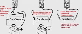
The main purpose of the ground electrode is to create protection from the effects of electric current. Grounding provides protection for humans and electrical appliances. There are two main types of grounding:
Working – primarily serves to ensure the safe operation of most electrical appliances. The basic task of this type of protection is to ensure uninterrupted use of electrical installations, as well as devices of this kind in their normal mode.
Protective – the main purpose is to ensure safety. This type of grounding allows you to reduce the likelihood of equipment failure when exposed to current or voltage surges.
This type provides human protection when working with electrical equipment.
The causes of dangerous current and voltage values are a lightning strike or improper operation of work equipment.
Differences between working and protective grounding
Working and protective grounding differ from each other primarily in purpose.
If the first is necessary to ensure the correct and uninterrupted operation of electrical equipment, then the second serves to protect people from electric shock.
It also protects equipment from damage in the event of a breakdown of any electrical device on the housing. If the building is equipped with a lightning rod, this type of grounding will protect the devices from overload in the event of a lightning strike.
Working grounding of electrical installations, in the event of an emergency, will play a protective role, but its main function is to ensure the correct uninterrupted operation of electrical equipment.
In its unchanged form, functional grounding is used only in industrial facilities. In residential buildings, a grounding conductor is used, which is connected to the outlet. However, there are household appliances in the house that pose a potential danger to the consumer, so it would not be superfluous to ground them using a solidly grounded neutral.
Household appliances that need to be connected to a working ground:
- Microwave.
- Oven and stove that run on electricity.
- Washing machine.
- System unit of a personal computer.
Comparison of natural and artificial contour
Natural contour - a set of metal structures in contact with the ground to provide grounding. A natural type grounding electrode can be:
- a type of metal structures, such as reinforcement of building structures, that are in contact with the ground;
- pipelines for various purposes located in the ground.
This type of protective circuit must be connected to the object by at least two grounding elements. They are usually mounted in different parts of the structure.
Cannot be used as natural grounding:
- pipe metal structures of toxic substances and flammable gases;
- pipes used corrosion-resistant insulation;
- sewer lines and heating systems.
Artificial circuit - special metal devices installed in the ground to implement grounding. Examples of such contours:
- steel beams, pipes, angles, rods installed in the ground;
- metal sheets of various shapes laid in the ground.
An example of a ground electrode in the form of a steel rod with a connected ground conductor.
All elements of the artificial circuit must have corrosion-resistant electrical conductors (zinc, copper).
Primary requirements
Most of the relevant recommendations and rules regulate the design and placement of such a component of the grounding system. Requirements that an artificial grounding system must meet:
- For arid areas, there is a separate technology for grounding using reinforced concrete structures.
- The artificial grounding conductor cannot be painted. This is explained by the fact that any coloring acts as an insulator. The insulation will prevent current from flowing into the soil. The artificial grounding conductor must have a natural color.
- Welding seams (conductor connections) must be painted. Painted with bitumen paint, premature destruction of the connecting elements is prevented.
- Non-standard (reduced) electrode values are used exclusively when installing temporary electrical installations.
The optimal choice of grounding material is considered to be round reinforcement. Justification for this priority:
- Minimum metal consumption. Consequently, the cost of the grounding device is reduced.
- The corrosion resistance of such an electrode is significantly higher than that of its analogues.
- Ease of installation.
In addition to the profile requirements, there is a recommended standardization of the parameters (dimensions) of the material used to create an artificial grounding element.
Advantages and disadvantages of grounding devices
- Natural grounding devices are best used in cases where they allow all the safety requirements placed on them to be met.
- It is recommended to use artificial grounding loops to reduce the magnitude of currents that will flow into the ground through natural grounding conductors.
- To a greater extent, you can get by using only natural grounding devices. This will primarily save the cost of purchasing additional materials, and will also significantly reduce labor and physical costs. In addition, the use of natural devices is much easier to use than artificial ones.
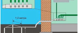
Why are several ground electrodes made?
An electrical installation cannot be equipped with only one ground electrode, since the soil is a non-linear conductor. The ground resistance is strongly dependent on the voltage and area of contact with the inserted working ground pins.
One ground electrode will have insufficient contact area with the soil to ensure uninterrupted operation of the electrical installation. If you install 2 ground electrodes at a distance of several meters from each other, then a sufficient contact area with the ground appears. However, it should be remembered that the metal parts of the grounding cannot be separated too far, since the connection between them will be interrupted.
As a result, only two ground electrodes installed separately in the soil will remain, not connected to each other in any way. The optimal distance between two ground loops is 1-2 meters.
Rules for the construction of electrical installations (PUE)
In connection with the PUE, new electrical installations are being constructed and old ones are being reconstructed. We are talking about structures powered by alternating and direct currents with a voltage of less than 750 kV.
The above rules should be applied to existing structures if this helps to improve the performance and reliability of the electrical structure, and also contributes to the improvement of safety requirements.
The PUE gives instructions for the implementation and repair of all electrical installations, as well as their adjustment and repair.
Using the foundation as a natural grounding device
Preparation for welding steel reinforcing bars before pouring a concrete foundation.
Grounding conductors in the form of reinforced concrete foundations are used only in cases where concrete structures are designed in the form of separate blocks connected to each other. For a more reliable construction, the reinforcing piles are welded together using electric arc welding.
Today, the use of ground electrodes on reinforced concrete foundations of buildings is possible only when the soil moisture content is no more than 3%. Structures can only be affected by slightly aggressive or non-aggressive substances.
Using pipes as a natural grounding conductor
If the pipeline grounding switch is used as a basis, then the connection is made on the pipe valve through a jumper. Using a sewer pipe as a grounding conductor is highly undesirable, since there will be weak electrical contact at the joints of the metal structure.
Water pipes or pipes intended for heating cannot be used as a grounding conductor. There may be non-conductive inserts in the pipeline, which will therefore disrupt electrical contact. Corrosion also affects poor electrical conductivity.
Grounding via reinforced concrete foundation
The choice of such a structure as a grounding device can only be carried out if the physical foundations of the foundation (hydrophilicity of concrete) correspond to the quantitative indicators of soil moisture.
It is permissible to implement such a technological grounding option only if the moisture content of the soil on which the object is located is above 3%. A lower indicator of this soil characteristic will affect the hydrophilicity of concrete: powerful electrical resistance will occur, and the reinforced concrete structure will lose the properties of the ground electrode.
It is more practical to use a natural grounding system using a reinforced concrete foundation under the following conditions:
- the presence of a non-aggressive environment (groundwater with minimal hardness);
- lack of waterproofing;
- the presence of additional foundation protection (bitumen coating).
Regulatory standardization of the use of this type of grounding conductor provides options when it is prohibited to use it in the grounding system of a facility.
Connecting elements in a structure
It doesn’t matter what the structural parts are made of, metal or reinforced concrete, the main thing is that they must be connected in such a way that an electrical circuit is formed in these parts, passing through the metal itself. If the structure is reinforced concrete, then the embedded parts in it should be additionally prepared. They must be present on each floor of the property.
Thanks to these embedded parts, the device can connect electrical or technological equipment that must be grounded. If there are connections in buildings in the form of bolts, rivets or welds, then they will be sufficient to install a permanent electrical circuit. If such connections are not available, then flexible jumpers can be used, which are welded to the structural elements. The cross-section of the jumpers should be from one hundred square millimeters.
What cannot be used from reinforced concrete structures as grounding conductors? If the prefabricated foundation is made of reinforced concrete, then it is better not to connect a natural ground electrode to it. If possible, it is better to first connect the reinforcement of nearby blocks to each other, and only then begin making natural grounding. If such a connection is not possible, then it is best to make an artificial ground loop.
Reinforced concrete structures are connected to each other as follows: if the building’s foundation is made of piles, then the reinforcement of the piles is connected to the foundation blocks or to the grillage reinforcement using electric arc welding. But such welding is not suitable for spatial columns and metal frames. In this case, spot welding is used.
When reinforced concrete structures are not used
Precast concrete foundations have good structural characteristics in both structural strength and durability. It is not prohibited to connect a grounding conductor to such a foundation.
The main thing is to make the correct connection of structural elements. By fastening the reinforcement of adjacent blocks together, you can verify the reliability of the structure, and then begin production of the grounding device.
If it is not possible to make such a connection, it is better to resort to the use of an artificial ground electrode. It is necessary to make connections of this type of structure taking into account the profile standardization of the production of such work.
The principle of connecting reinforced concrete structures
Connections between parts are made based on the formation of an electrical circuit between them (passes through metal). Embedded elements inside reinforced concrete structures are prepared in advance, through which the connection of technological or electrical equipment is realized for subsequent grounding.
The presence of bolts, rivets, welding or similar connections will allow the installation of a permanent electrical switching circuit. In the absence of such connections, there is an option to create similar connections using flexible jumpers. These elements are welded to parts of the structure. The standardization of the cross-section of jumpers is 100 sq. mm and above.