An independent release is not a very suitable device for controlling fire alarm engineering systems.
But its use can be found more and more often - I think because it is the least intellectually expensive.
It’s easiest to add an external control channel to an already established tangle of engineering systems using independent releases.
This is, of course, if you don’t bother with all sorts of integrity controls and feedbacks.
I paid a lot of attention to the issues of using independent releases in articles about methods of controlling the OZK and correctly turning off ventilation, although I was going to go over them in passing, as one of the not the best options.
There seems to be nothing to add to the material presented there. But it seems that the topic will become more and more relevant, and, probably, manufacturers will release more sophisticated equipment for independent releases, and their use will be more formalized in the standards.
So the theory about the use of independent releases will require a separate article.
Everything related to the use of releases in fire systems will be monitored here.
How to send a signal to an independent release from the APS?
Controlling independent releases using an APS (automatic fire alarm) signal entails a number of requirements.
Moreover, these requirements exist not just for the control method itself, but in general for the entire fire protection system (fire protection system).
The independent release control must contain:
1. Integrity monitoring with alarm about its violation
2. Feedback about the state of the controlled machine.
Hence:
1. The APS must have a controlled output capable of controlling an independent release.
2. The APS must contain a technological loop to monitor the state of the machine, controlled by an independent release.
An independent release in circuits used in conjunction with a fire alarm is similar to a valve in fire ventilation systems.
But there is a significant difference - the release has a much lower winding resistance and a much higher current consumption than the valve.
Therefore, the shunt coil cannot be energized forever, like a valve.
There are not so many ways to properly control an independent release with circuit monitoring, if we consider only the correct methods - and in general, I have not seen any methods implemented in reality.
But only three are correct.
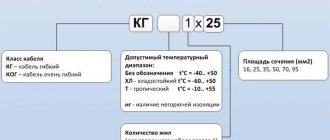
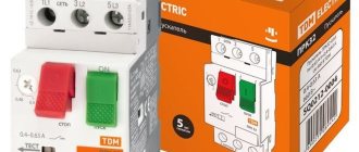
Types of built-in releases
The first type is household ones. Their mechanism is triggered solely by the voltage that passes through the main circuit of the circuit breaker. Such devices are able to work remotely, unlike other protective systems for electrical networks. The release actively helps to disconnect from the network all devices and sources that regularly consume power in the event of a noticeable voltage deviation from the specified norm. However, such an installation also has a drawback, which converts the energy loss into heat generation and conducts it through the insulating conductor. Sometimes this factor leads to incorrect disconnection of the switch.
To the electrician's piggy bank!
Monitor the operating characteristics of the mechanism; in some cases, deviations from the norm may be observed.
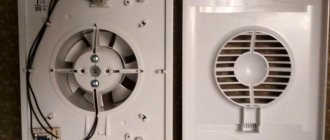
Appearance of the release
In the latest samples and systems, this drawback is eliminated due to the presence of a bimetallic plate, which has not previously been used in the formation of an automatic protective device. This helps prevent the machine from overheating.
What can an independent release be used to control?
An independent release can have only one control effect - turn off the power. You can only turn on the power manually.
I have come across the following options for using an independent release to transmit control action from a fire alarm system:
- Turn off the power supply to the general ventilation.
- Turn off the power supply to the OZK valves.
- Turn off the power of the music broadcast monitor.
I can't imagine any other options.
Perhaps for de-energizing electromagnetic locks of emergency exits.
I once saw an attempt at such a solution, but it turned out that electromagnetic locks use 12V power from a redundant power source with a battery - here turning off the 220V power will not help much.
What types of independent releases are there?
It is not possible to use an arbitrary independent release: the release must be of the same series as the circuit breaker being switched off. Different manufacturers have different series of electrical equipment.
There are independent releases that are triggered by voltages of 12, 24, 60, 110, 220V.
Not all models of independent releases have both high- and low-current versions.
For some independent releases, writing “low-current” does not raise your hand, since the operating current at 12V is stated to be 6A. The “low-voltage” version of the independent release also does not mean 12V - so I may be confused in terms.
Very few models of low-current independent releases have the ability to operate from 12V - 24V independent releases are more common.
A series of electrical equipment, in addition to an independent release, must also contain an additional signal contact.
A release is connected to the machine on the right, and a signal contact is connected to the left.
Or vice versa.
There are also independent releases with an integrated signal contact.
But using this contact to transmit a signal to the alarm system is problematic for some models, since one pole of the contact can be combined with the control line.
The contact is intended for signaling in high voltage circuits. And to stop supplying the control signal after the release is triggered to limit the time the coil is energized.
If any independent release for 220V can be used, then the low-current release must have an operating current of no more than the maximum current of the APS output.
Not all independent releases have accompanying documentation containing the tripping current.
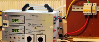
Here are the control signal parameters for the most common “S2C-A” releases for ABB S200 series circuit breakers:
Similar currents are declared for similar independent releases.
Therefore, the question arises when the documentation for the release indicates a significantly lower current - is there a catch here?
Typically, a lower current is required to trip the residual current circuit breakers.
The ABB F2C-A1 release for residual current circuit breakers of the F200 series has the following parameters:
It is already possible to obtain a 12V 0.88A signal from a fire alarm system, but not all equipment can be connected through the F200 series residual current switch.
We will consider specific models of independent releases in the article Independent releases: characteristics and prices.
Automatic network protection switch with electromagnetic release
Having figured out how a machine with a thermal release works, let's move on to the next question. The protective device, the operation of which we have just analyzed, does not operate immediately (it takes at least a second), so it is not able to effectively protect the circuit from short circuit overcurrents. To solve this problem, an electromagnetic release is additionally installed in the AV.
Electromagnetic type circuit breaker releases include an inductor (solenoid) as well as a core. When the circuit is operating normally, the flow of electrons passing through the solenoid creates a weak magnetic field that is unable to influence the function of the network. When a short circuit occurs, the current instantly increases tens of times, and the magnetic field power increases in proportion to it. Under its influence, the ferromagnetic core instantly moves to the side, affecting the shutdown mechanism.
Since the process of strengthening the magnetic field during a short circuit occurs in a fraction of a second, the electromagnetic release under its influence is triggered instantly, turning off the power to the network. This allows you to avoid serious consequences associated with short-circuit overcurrents.
An example of an incorrect, but very popular way to control an independent release.
The EO project contains the following diagram (can be enlarged):
There are several such circuits in the project for different distribution cabinets - as a result, there are about a dozen independent releases.
The directions of electrical equipment to be disconnected are powered through the following group: automatic + independent release:
Moreover, in the EO project they go further and indicate exactly how the independent fire alarm release should operate:
That is, not a single section of the ventilation shutdown circuits is controlled.
But the EO cabinets have already been ordered, assembled and installed.
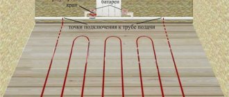
The independent release control circuit in a fire alarm project, corresponding to existing electrical equipment, can only look like this:
Here you can see the efforts to adapt it to the requirements of monitoring the integrity of control circuits.
The source of the control signal will be the control and starting unit “S2000-KPB” with monitoring of the integrity of the circuit to the relay amplifier “UK-VK”:
They even introduce monitoring of the state of the ventilation system machine using the signal loop of the Signal-20M device:
But the section “UK-VK” -> Independent release is not controlled in any way.
Discussion on the forum of comments on the use of independent releases.
Correct ways to control shunt releases.
Addressable APS device for controlling a 220V valve.
Almost all manufacturers of APS equipment include a module for controlling a 220V drive with control of the drive winding.
The module was designed to control reversible drives of smoke exhaust and air pressure valves - in this article we found out that without such modules the valves will be difficult.
MDU-1 (TD Rubezh), S2000-SP4 (Bolid), BR-4 (PSK-Module), ISM-220 (Sigma), MAKS-U (Unitronic), VERS-ASD(U) (VERS), Z- 027 (Z-Line), BUOK (Forind), BR-1+ (Automation Cluster), BUKP-4 (Gulfstream-Avtomatika), BUEP (TDS Pribor), KUPT-06 (Mirten), IMP3 (Liora), Karat BR4 (Siberian Arsenal), BR-1M (Sys PB), ISM220 ISP4 (Rubicon), MS322 (Plasma-T), MAKS-URP (Unitronic), BKPBKP220/RK (Hephaestus), Astra-BRA (Astra-A Teco).
The cost of the modules is 2160-5500 rubles .
Probably all these modules can be used to control an independent release.
Of course, it’s impossible to just pick and choose the module you like.
The security system used at the facility will already be given as a constant - and only the module that is included in it will need to be used.
Here is a diagram for controlling an independent release and monitoring the state of the machine using the equipment of the S2000-SP4 Bolid addressable valve control modules:
I’m not sure about the value of the resistor in the power circuit, and in general, each module will have its own resistors.
The correct circuit for an EO project using monitored output and state monitored modules is:
The use of high-voltage independent releases entails the need for an addressable alarm system.
APS output expander for controlling 12/24V actuators.
The task of controlling 12/24V actuators has been worked out more thoroughly by manufacturers of fire alarm systems.
This is not surprising, because there are many more types of low-current actuators than 220V actuators.
The same voltage outputs of the OK type (open collector) are suitable here as for controlling warning devices and evacuation displays.
Therefore, the task of organizing a control circuit for a low-voltage independent release seems simpler than for a high-voltage one.
There is just one big BUT - the current consumed by the independent release at the moment of operation is quite large.
And the maximum permissible current of the OK type output is limited.
In common addressable systems, “S2000-SP4” expanders and “RM-4K” addressable modules have a maximum output current of 2A.
The highest output current of all APS devices known to me is 2.5A, and has the addressable module “S2000-SP2 ISP.2”.
In the documentation for different independent releases you can find different cut-off currents.
And theoretically, it is possible to select models of low-voltage independent releases suitable for control from a fire alarm.
Although for most independent releases at 12/24V, the current consumed at cutoff is more than 3A.
But all this should happen with the coordinated work of the designers of the EO and APS sections of the project, which sounds like fantasy.
Moreover, a suitable independent release will not be 12V, but 24V - not a very common voltage for APS in Russia. That is, it is necessary to make a decision in advance that the entire APS system will be 24V.
One more BUT - I have never come across a low-voltage independent release. After all, the configuration of the electrical equipment cabinets is indicated in the EO project - and there will be nothing low-current there and no one will bother about some low-current devices with their stupid fire alarms.
The use of low-voltage independent releases should be included in design decisions at the very beginning of the design.
Special addressable APS module for control and monitoring of an independent release.
I have only seen two such devices.
“ISM220” is an addressable executive module for switching loads in 220 V circuits from the Rubicon system.
With one device at a price of 1600 rubles , we control the independent release, monitoring the integrity of the control circuit, and monitor the condition of the circuit breaker controlled by the release.
But to use this gadget, it is necessary that the Rubicon address system be implemented at the facility.
Addressable control module "MAX-U", costing 2740 rubles .
Costs even more than some valve control modules. The MAKS-URP valve control module, part of the same system, costs only 2160 rubles .
Special devices for monitoring and controlling the 220V actuator.
But what to do if the fire alarm is assembled on one monoblock fire alarm device?
There are no address lines - only analog loops.
How to control an independent release, say, from the Signal-20M device?
It will be necessary to involve specialized equipment for transmitting the control signal for fire protection equipment.
This issue is worked out as fully as possible in the composite PPU (firefighter control device) “Hephaestus”, the modules of which can be used both in a single complex and independently.
For our purposes, the control device and communication lines “UKLSiP(S)220”, which costs only 1085 rubles, .
Then all issues with monitoring the integrity of the control circuit will be removed and even two options for transmitting a fault signal will appear.
The independent release here is an actuator device (ED) that is switched on in case of fire.
If there are several independent releases, then it will be necessary to use the switching and diagnostic device “UK-D (02)” as an intermediary, which costs 1120 rubles.
In these connection diagrams, the valve coil will be the independent release coil.
The devices already have a controlled 2220V output.
There are two control devices that have a power output with integrity monitoring.
VERS-PU has an engineering equipment control relay (RUIO) with a built-in power line control device (UKSL):
The control circuit from the VERS-PU operating manual can be changed using an independent release as a control device.
The device costs 7,100 rubles and is designed to control fire extinguishing - its use in an alarm system does not make sense.
The Sprut-2 control device has 5 (10) 220V power outputs, each with integrity monitoring.
Moreover, if the power control circuit breaks, both the “Alarm” signal and the “Automation disabled” signal can be generated.
These are diagrams from the instruction manuals and in them “Relay K” and “Coil 220V” and there will be an independent release in our case.
This device is intended for use in a fire extinguishing system and its cost of 38,000 rubles makes it impossible to use it as part of an fire extinguishing system.
Limiting the duration of the control pulse and monitoring integrity.
If the independent release is connected according to a circuit where the coil is disconnected from the control circuit after activation, then an “Alarm” signal will appear in the fire alarm system as a result of a break in the control circuit.
To avoid this, it is necessary to connect the release coil directly to the PPU, bypassing additional contacts. After all, the activation time of the fire alarm output can be limited when configuring the system.
Perhaps the signal generated by a break will be sufficient to diagnose an emergency situation and there is no need to use an additional signal contact.
Both a break in the control circuit and a physical shutdown of the machine will cause the same “Alarm” signal.
I don’t know if it’s possible to make such a generalization based on GOST R 53325-2012, which says:
7.6.4.1 The device must ensure that the light indication and sound alarm are turned on in the “Fault” mode in the presence of the following events: - detection of a violation of the integrity (break, short circuit) of wired communication lines or a violation of communication between the device and external technical means or between components of the device; Note - It is acceptable that information about a fault in a wired alarm control panel of an addressless control panel is not displayed after receiving information about a fire from this alarm system. — loss or decrease below the permissible value of the power supply voltage at any power supply input; — receiving a fault signal from external technical means interacting with the device; — absence of signals confirming the activation of fire protection means after their activation by the device (in accordance with the operating algorithm of the device); — identification of malfunctions of individual components or units of the device (if the device has a self-test function). 7.6.4.2 Light indication in the “Fault” mode should be carried out by turning on the generalized yellow “Fault” indicator. Interpretation of the direction and type of malfunction should be carried out by yellow single “Fault” indicators in the directions or displayed on the SOTI. Notes 1 Information about the detection of a break or short circuit in a wired communication line may be combined into general information about the malfunction of a given communication line. 2 It is allowed to display information about the malfunction of components or units of the device and software failure using separate generalized single indicators. 3 It is allowed that there is no additional display on the SOTI of information about a power supply fault on the power supply inputs if there are separate indicators displaying the status of each input. 7.6.4.3 Information about the direction and type of fault displayed on the ICT shall be available directly or upon request. 7.6.4.4 Resetting the light indication and sound alarm about a malfunction in devices that have a device for recording and storing event data can be carried out automatically after the malfunction is eliminated. In this case, it must be ensured that information about the registered fault is stored in the recording device. Otherwise, automatic reset of the light indication and sound alarm about a malfunction is not allowed.
Types of switches
All machines are divided according to the type of release. They are divided into 6 types:
- thermal;
- electronic;
- electromagnetic;
- independent;
- combined;
- semiconductor.
They very quickly recognize emergency situations, such as:
- the occurrence of overcurrents - an increase in the current strength in the electrical network that exceeds the rated current of the circuit breaker;
- voltage overload – short circuit in the circuit;
- voltage fluctuations.
At these moments, the contacts in the automatic releases open, which prevents serious consequences in the form of damage to wiring and electrical equipment, which very often leads to fires.
Thermal switch
It consists of a bimetallic plate, one of the ends of which is located next to the release device of the automatic release. The plate is heated by the current passing through it, hence the name. When the current begins to increase, it bends and touches the trigger bar, which opens the contacts in the “machine”.
The mechanism operates even with slight excesses of the rated current and an increased response time. If the load increase is short-term, the switch does not trip, so it is convenient to install it in networks with frequent but short-term overloads.
Advantages of a thermal release:
- absence of contacting and rubbing surfaces;
- vibration stability;
- budget price;
- simple design.
The disadvantages include the fact that its operation largely depends on the temperature regime. It is better to place such machines away from heat sources, otherwise there is a risk of numerous false alarms.
Electronic switch
Its components include:
- measuring devices (current sensors);
- Control block;
- electromagnetic coil (transformer).
At each pole of the electronic circuit breaker there is a transformer that measures the current passing through it. The electronic module that controls the trip processes this information, comparing the obtained result with the specified one. In the event that the resulting indicator is greater than the programmed one, the “machine” will open.
There are three trigger zones:
- Long delay. Here, the electronic release serves as a thermal release, protecting the circuits from overloads.
- Short delay. Provides protection against minor short circuits that usually occur at the end of the protected circuit.
- The working area “instantly” provides protection against high-intensity short circuits.
Pros - a large selection of settings, maximum accuracy of the device to a given plan, the presence of indicators. Cons: sensitivity to electromagnetic fields, high price.
Electromagnetic
This is a solenoid (a coil of wound wire), inside of which there is a core with a spring that acts on the release mechanism. This is an instant action device. As the supercurrent flows through the winding, a magnetic field is generated. It moves the core and, exceeding the force of the spring, acts on the mechanism, turning off the “automatic machine”.
Pros: resistance to vibration and shock, simple design. Cons – forms a magnetic field, triggers instantly.
This is an additional device to automatic releases. With its help, you can turn off both single-phase and three-phase circuit breakers located at a certain distance. To activate the independent release, voltage must be applied to the coil. To return the machine to its original position, you must manually press the “return” button.
Important! The phase conductor must be connected from one phase from under the lower terminals of the switch. If it is connected incorrectly, the independent switch will fail.
Basically, independent automatic machines are used in automation panels in highly ramified power supply devices of many large facilities, where control is transferred to the operator’s console.
Combination switch
It has both thermal and electromagnetic elements and protects the generator from overloads and short circuits. To operate the combined automatic release, the current of the thermal circuit breaker is indicated and selected: the electromagnet is designed for 7–10 times the current, which corresponds to the operation of heating networks.
The electromagnetic elements in the combination switch provide instantaneous protection against short circuits, and the thermal elements protect against overloads with a time delay. The combined machine is switched off when any of the elements is triggered. During short-term overcurrents, none of the types of protection are triggered.
Semiconductor switch
It consists of alternating current transformers, magnetic amplifiers for direct current, a control unit and an electromagnet that functions as an independent automatic release. The control unit helps set the selected contact release program.
Its settings include:
- regulation of the rated current in the device;
- setting the time;
- triggered when a short circuit occurs;
- protective switches against overcurrent and single-phase short circuit.
Pros - a large selection of regulation for different power supply schemes, ensuring selectivity to series-connected circuit breakers with fewer amperes.
Cons: high cost, fragile control components.