An independent release is not a very suitable device for controlling fire alarm engineering systems.
But its use can be found more and more often - I think because it is the least intellectually expensive.
It’s easiest to add an external control channel to an already established tangle of engineering systems using independent releases.
This is, of course, if you don’t bother with all sorts of integrity controls and feedbacks.
I paid a lot of attention to the issues of using independent releases in articles about methods of controlling the OZK and correctly turning off ventilation, although I was going to go over them in passing, as one of the not the best options.
There seems to be nothing to add to the material presented there. But it seems that the topic will become more and more relevant, and, probably, manufacturers will release more sophisticated equipment for independent releases, and their use will be more formalized in the standards.
So the theory about the use of independent releases will require a separate article.
Everything related to the use of releases in fire systems will be monitored here.
How to send a signal to an independent release from the APS?
Controlling independent releases using an APS (automatic fire alarm) signal entails a number of requirements.
Moreover, these requirements exist not just for the control method itself, but in general for the entire fire protection system (fire protection system).
The independent release control must contain:
1. Integrity monitoring with alarm about its violation
2. Feedback about the state of the controlled machine.
Hence:
1. The APS must have a controlled output capable of controlling an independent release.
2. The APS must contain a technological loop to monitor the state of the machine, controlled by an independent release.
An independent release in circuits used in conjunction with a fire alarm is similar to a valve in fire ventilation systems.
But there is a significant difference - the release has a much lower winding resistance and a much higher current consumption than the valve.
Therefore, the shunt coil cannot be energized forever, like a valve.
There are not so many ways to properly control an independent release with circuit monitoring, if we consider only the correct methods - and in general, I have not seen any methods implemented in reality.
But only three are correct.
Checking the functionality of releases
The functionality check includes the following steps:
- Visual inspection of the switch. There should be no mechanical damage on the device body: chips or cracks. Pay attention to the tightness of the parts, the quality of fasteners and clamps. Make a few test manipulations of “on ↔ off” manually. In the on position, the device should click into place and then turn off freely.
- Loading the device. The test consists of determining the response time of the release when power is supplied with an adjustable current strength on a special stand. The obtained result is compared with the typical time-current characteristic of the AB model.
The modern market of electrical equipment offers the consumer a wide range of releases. These devices are equipped with devices of 1-3 phase alternating AC and direct current DC and voltage up to 1000 V.
What can an independent release be used to control?
An independent release can have only one control effect - turn off the power. You can only turn on the power manually.
I have come across the following options for using an independent release to transmit control action from a fire alarm system:
- Turn off the power supply to the general ventilation.
- Turn off the power supply to the OZK valves.
- Turn off the power of the music broadcast monitor.
I can't imagine any other options.
Perhaps for de-energizing electromagnetic locks of emergency exits.
I once saw an attempt at such a solution, but it turned out that electromagnetic locks use 12V power from a redundant power source with a battery - here turning off the 220V power will not help much.
How to properly use an independent release in a fire protection system
An independent release is not a very suitable device for controlling fire alarm engineering systems.
But its use can be found more and more often - I think because it is the least intellectually expensive.
It’s easiest to add an external control channel to an already established tangle of engineering systems using independent releases.
This is, of course, if you don’t bother with all sorts of integrity controls and feedbacks.
I paid a lot of attention to the issues of using independent releases in articles about methods of controlling the OZK and correctly turning off ventilation, although I was going to go over them in passing, as one of the not the best options.
There seems to be nothing to add to the material presented there. But it seems that the topic will become more and more relevant, and, probably, manufacturers will release more sophisticated equipment for independent releases, and their use will be more formalized in the standards.
So the theory about the use of independent releases will require a separate article.
Everything related to the use of releases in fire systems will be monitored here.
What types of independent releases are there?
It is not possible to use an arbitrary independent release: the release must be of the same series as the circuit breaker being switched off. Different manufacturers have different series of electrical equipment.
There are independent releases that are triggered by voltages of 12, 24, 60, 110, 220V.
Not all models of independent releases have both high- and low-current versions.
For some independent releases, writing “low-current” does not raise your hand, since the operating current at 12V is stated to be 6A. The “low-voltage” version of the independent release also does not mean 12V - so I may be confused in terms.
Very few models of low-current independent releases have the ability to operate from 12V - 24V independent releases are more common.
A series of electrical equipment, in addition to an independent release, must also contain an additional signal contact.
A release is connected to the machine on the right, and a signal contact is connected to the left.
Or vice versa.
There are also independent releases with an integrated signal contact.
But using this contact to transmit a signal to the alarm system is problematic for some models, since one pole of the contact can be combined with the control line.
The contact is intended for signaling in high voltage circuits. And to stop supplying the control signal after the release is triggered to limit the time the coil is energized.
If any independent release for 220V can be used, then the low-current release must have an operating current of no more than the maximum current of the APS output.
Not all independent releases have accompanying documentation containing the tripping current.
Here are the control signal parameters for the most common “S2C-A” releases for ABB S200 series circuit breakers:
Similar currents are declared for similar independent releases.
Therefore, the question arises when the documentation for the release indicates a significantly lower current - is there a catch here?
Typically, a lower current is required to trip the residual current circuit breakers.
The ABB F2C-A1 release for residual current circuit breakers of the F200 series has the following parameters:
It is already possible to obtain a 12V 0.88A signal from a fire alarm system, but not all equipment can be connected through the F200 series residual current switch.
We will consider specific models of independent releases in the article Independent releases: characteristics and prices.
Device sensitivity
Before you get acquainted with the types of machines, you need to find out with what sensitivity the devices are suitable for home use, and which ones will be inappropriate. This indicator will indicate how quickly the device will respond to a power surge. It has several markings:
- A – used for super sensitive types of machines. They instantly detect a surge in the network and also react to it instantly. Most often they are used in production to protect expensive equipment. They are practically not suitable for household purposes.
- B - this marking is applied to those types of circuit breakers that respond with a slight delay. Manufacturers of expensive household appliances install them to protect the device itself. If a small failure occurs, the device reacts to it itself and does not turn off the entire network in the house.
- The C markings are for those circuit breakers that are capable of disconnecting the household network when the voltage increases or decreases significantly. If the jump is small, the device may turn off for a while, but then return to normal operation.
- The machine marked D is installed only in the panel that connects the house or apartment to the general system. Its sensitivity to voltage surges is minimal, so it is exclusively a backup option. If the voltage drop is very large, then the entire house or apartment is disconnected from the electrical network.
Classification of machines
There are different types of machines in relation to the type of current, rated voltage or current indicator and other technical characteristics. Therefore, you need to specifically understand each point separately.
Current type
In relation to this characteristic, machines are divided into:
- For operation on AC power;
- For operation in a DC network;
- Universal models.
Everything is clear here and no additional explanation is needed.
Based on rated current
The value of this characteristic will determine in the network what maximum value the circuit breaker can operate with. There are devices that can operate from 1 A to 100 A and more. The minimum value with which machines can be found on sale is 0.5 A.
Rated voltage indicator
This characteristic indicates what voltage this type of circuit breaker can operate with. Some can operate on a network with a voltage of 220 or 380 Volts - these are the most common options for domestic use. But there are machines that will cope well with higher rates.
By ability to limit the flow of electricity
According to this characteristic, the following are distinguished:
- Current-limiting - immediately eliminate the access of electric current to the device. Therefore, during a short circuit, neither the device nor the wiring of the electrical network are damaged.
- Non-current-limiting - operate much slower.
Other characteristics
The number of poles can be from one to four. Accordingly, they are called single-pole, double-pole, and so on.
By structure they are distinguished:
- Air;
- Modular;
- Molded case circuit breakers.
Based on the discharge speed, high-speed, normal and selective devices are produced. They can have a time delay function that can be inversely dependent on the current or independent of it. The time delay may not be set.
Automatic machines also have a drive, which can be manual, connected to a motor or a spring. Switches differ in the presence of free contacts and in the method of connecting conductors.
An important characteristic will be protection from environmental influences. Here we can highlight:
- IP protection;
- From mechanical impact;
- Current conductivity of the material.
All characteristics can be combined in various combinations. It all depends on the model and manufacturer.
Switch types
The machine inside contains a release, which, using a lever, latch, spring or rocker, can instantly disconnect the network from the supply of electricity. Types of circuit breakers are distinguished by the type of release. There are:
- Automatic switch with magnetic release - responds to surges instantly. Well suited for networks where short circuits occur frequently. The release is represented by a solenoid with a movable core. During the jump, the core is retracted and the circuit opens. Reacts in a split second.
- Thermal release switch – protects the electrical network from excessive load. The release is represented by a bimetallic plate. Under the influence of a current with an increased value, the plate heats up and bends, thereby turning off the supply of electricity. These types of machines are capable of responding from a few seconds or up to 1 minute to excess voltage. It all depends on what indicators the device is designed for.
Circuit breakers are much more cost effective than fuses. This is because after cooling, the machine can already be turned on, and it will work as it should if the cause of the overload is eliminated. The fuse needs to be replaced. It may not be available and replacing it may take a long time.
infoelectrik.ru
Topic: what types of electric machines are divided into, their types and classification.
A circuit breaker is an electrical device, the main purpose of which is to switch its operating state when a certain situation occurs.
Electric tomatoes combine two devices: a regular switch and a magnetic (or thermal) release, the task of which is to timely break the electrical circuit if the threshold current value is exceeded. Circuit breakers, like all electrical devices, also have different varieties, which divides them into certain types. Let's take a look at the main classifications of circuit breakers.
1" Classification of machines by number of poles:
a) single-pole circuit breakers
b) single-pole circuit breakers with neutral
c) two-pole circuit breakers
d) three-pole machines
e) three-pole circuit breakers with neutral
e) four-pole machines
2" Classification of automatic machines according to the type of releases.
The design of various types of circuit breakers usually includes 2 main types of releases (breakers) - electromagnetic and thermal. Magnetic circuit breakers are used for electrical protection against short circuits, while thermal circuit breakers are intended mainly to protect electrical circuits against a certain overload current.
3" Classification of circuit breakers by tripping current: V, C, D, (A, K, Z)
GOST R 50345-99, according to instantaneous tripping current, automatic machines are divided into the following types:
a) type “B” - over 3•In to 5•In inclusive (In is the rated current)
b) type “C” - over 5•In up to 10•In inclusive
B) type “D” - over 10•In to 20•In inclusive
Machine manufacturers in Europe have a slightly different classification. For example, they have an additional type “A” (over 2•In to 3•In). Some manufacturers of circuit breakers also have additional switching curves (ABB has circuit breakers with K and Z curves).
4" Classification of machines according to the type of current in the circuit: direct, alternating, both.
Rated electric currents for the main circuits of the release are selected from: 6.3; 10; 16; 20; 25; 32; 40; 63; 100; 160; 250; 400; 630; 1000; 1600; 2500; 4000; 6300 A. Automatic machines are also additionally produced with rated currents of the main electrical circuits of the automatic machines: 1500; 3000; 3200 A.
5" Classification according to the presence of current limitation:
a) current-limiting
b) non-current limiting
6" Classification of automatic machines by types of releases:
a) with overcurrent release
b) with independent release
c) with minimum or zero voltage release
7" Classification of machines according to time delay characteristics:
a) without time delay
b) with a time delay independent of current
c) with a time delay inversely dependent on the current
d) with a combination of the specified characteristics
8" Classification according to the presence of free contacts: with contacts and without contacts.
9" Classification of machines according to the method of connecting external wires:
a) with rear connection
b) with front connection
c) with combined connection
d) with universal connection (both front and rear).
10" Classification by type of drive: manual, motor and spring.
electrohobby.ru
An example of an incorrect, but very popular way to control an independent release.
The EO project contains the following diagram (can be enlarged):
There are several such circuits in the project for different distribution cabinets - as a result, there are about a dozen independent releases.
The directions of electrical equipment to be disconnected are powered through the following group: automatic + independent release:
Moreover, in the EO project they go further and indicate exactly how the independent fire alarm release should operate:
That is, not a single section of the ventilation shutdown circuits is controlled.
But the EO cabinets have already been ordered, assembled and installed.
The independent release control circuit in a fire alarm project, corresponding to existing electrical equipment, can only look like this:
Here you can see the efforts to adapt it to the requirements of monitoring the integrity of control circuits.
The source of the control signal will be the control and starting unit “S2000-KPB” with monitoring of the integrity of the circuit to the relay amplifier “UK-VK”:
They even introduce monitoring of the state of the ventilation system machine using the signal loop of the Signal-20M device:
But the section “UK-VK” -> Independent release is not controlled in any way.
Discussion on the forum of comments on the use of independent releases.
Types of releases
Releases are the main operating components of the automatic circuit breaker. Their task is to break the circuit when the permissible current value is exceeded, thereby stopping the supply of electricity to it. There are two main types of these devices, differing from each other in the principle of tripping:
- Electromagnetic.
- Thermal.
Electromagnetic type releases ensure almost instantaneous operation of the circuit breaker and de-energization of a section of the circuit when a short circuit overcurrent occurs in it.
They are a coil (solenoid) with a core that is drawn inward under the influence of a large current and causes the tripping element to operate.
The main part of the thermal release is a bimetallic plate. When a current exceeding the rated value of the protective device passes through the circuit breaker, the plate begins to heat up and, bending to the side, touches the disconnecting element, which trips and de-energizes the circuit. The time it takes for the thermal release to operate depends on the magnitude of the overload current passing through the plate.
Some modern devices are equipped as an addition with minimum (zero) releases. They perform the function of turning off the AV when the voltage drops below the limit value corresponding to the technical data of the device. There are also remote releases, with the help of which you can not only turn off, but also turn on the AV, without even going to the distribution board.
The presence of these options significantly increases the cost of the device.
Correct ways to control shunt releases.
Addressable APS device for controlling a 220V valve.
Almost all manufacturers of APS equipment include a module for controlling a 220V drive with control of the drive winding.
The module was designed to control reversible drives of smoke exhaust and air pressure valves - in this article we found out that without such modules the valves will be difficult.
MDU-1 (TD Rubezh), S2000-SP4 (Bolid), BR-4 (PSK-Module), ISM-220 (Sigma), MAKS-U (Unitronic), VERS-ASD(U) (VERS), Z- 027 (Z-Line), BUOK (Forind), BR-1+ (Automation Cluster), BUKP-4 (Gulfstream-Avtomatika), BUEP (TDS Pribor), KUPT-06 (Mirten), IMP3 (Liora), Karat BR4 (Siberian Arsenal), BR-1M (Sys PB), ISM220 ISP4 (Rubicon), MS322 (Plasma-T), MAKS-URP (Unitronic), BKPBKP220/RK (Hephaestus), Astra-BRA (Astra-A Teco).
The cost of the modules is 2160-5500 rubles .
Probably all these modules can be used to control an independent release.
Of course, it’s impossible to just pick and choose the module you like.
The security system used at the facility will already be given as a constant - and only the module that is included in it will need to be used.
Here is a diagram for controlling an independent release and monitoring the state of the machine using the equipment of the S2000-SP4 Bolid addressable valve control modules:
I’m not sure about the value of the resistor in the power circuit, and in general, each module will have its own resistors.
The correct circuit for an EO project using monitored output and state monitored modules is:
The use of high-voltage independent releases entails the need for an addressable alarm system.
APS output expander for controlling 12/24V actuators.
The task of controlling 12/24V actuators has been worked out more thoroughly by manufacturers of fire alarm systems.
This is not surprising, because there are many more types of low-current actuators than 220V actuators.
The same voltage outputs of the OK type (open collector) are suitable here as for controlling warning devices and evacuation displays.
Therefore, the task of organizing a control circuit for a low-voltage independent release seems simpler than for a high-voltage one.
There is just one big BUT - the current consumed by the independent release at the moment of operation is quite large.
And the maximum permissible current of the OK type output is limited.
In common addressable systems, “S2000-SP4” expanders and “RM-4K” addressable modules have a maximum output current of 2A.
The highest output current of all APS devices known to me is 2.5A, and has the addressable module “S2000-SP2 ISP.2”.
In the documentation for different independent releases you can find different cut-off currents.
And theoretically, it is possible to select models of low-voltage independent releases suitable for control from a fire alarm.
Although for most independent releases at 12/24V, the current consumed at cutoff is more than 3A.
But all this should happen with the coordinated work of the designers of the EO and APS sections of the project, which sounds like fantasy.
Moreover, a suitable independent release will not be 12V, but 24V - not a very common voltage for APS in Russia. That is, it is necessary to make a decision in advance that the entire APS system will be 24V.
One more BUT - I have never come across a low-voltage independent release. After all, the configuration of the electrical equipment cabinets is indicated in the EO project - and there will be nothing low-current there and no one will bother about some low-current devices with their stupid fire alarms.
The use of low-voltage independent releases should be included in design decisions at the very beginning of the design.
Special addressable APS module for control and monitoring of an independent release.
I have only seen two such devices.
“ISM220” is an addressable executive module for switching loads in 220 V circuits from the Rubicon system.
With one device at a price of 1600 rubles , we control the independent release, monitoring the integrity of the control circuit, and monitor the condition of the circuit breaker controlled by the release.
But to use this gadget, it is necessary that the Rubicon address system be implemented at the facility.
Addressable control module "MAX-U", costing 2740 rubles .
Costs even more than some valve control modules. The MAKS-URP valve control module, part of the same system, costs only 2160 rubles .
Special devices for monitoring and controlling the 220V actuator.
But what to do if the fire alarm is assembled on one monoblock fire alarm device?
There are no address lines - only analog loops.
How to control an independent release, say, from the Signal-20M device?
It will be necessary to involve specialized equipment for transmitting the control signal for fire protection equipment.
This issue is worked out as fully as possible in the composite PPU (firefighter control device) “Hephaestus”, the modules of which can be used both in a single complex and independently.
For our purposes, the control device and communication lines “UKLSiP(S)220”, which costs only 1085 rubles, .
Then all issues with monitoring the integrity of the control circuit will be removed and even two options for transmitting a fault signal will appear.
The independent release here is an actuator device (ED) that is switched on in case of fire.
If there are several independent releases, then it will be necessary to use the switching and diagnostic device “UK-D (02)” as an intermediary, which costs 1120 rubles.
In these connection diagrams, the valve coil will be the independent release coil.
The devices already have a controlled 2220V output.
There are two control devices that have a power output with integrity monitoring.
VERS-PU has an engineering equipment control relay (RUIO) with a built-in power line control device (UKSL):
The control circuit from the VERS-PU operating manual can be changed using an independent release as a control device.
The device costs 7,100 rubles and is designed to control fire extinguishing - its use in an alarm system does not make sense.
The Sprut-2 control device has 5 (10) 220V power outputs, each with integrity monitoring.
Moreover, if the power control circuit breaks, both the “Alarm” signal and the “Automation disabled” signal can be generated.
These are diagrams from the instruction manuals and in them “Relay K” and “Coil 220V” and there will be an independent release in our case.
This device is intended for use in a fire extinguishing system and its cost of 38,000 rubles makes it impossible to use it as part of an fire extinguishing system.
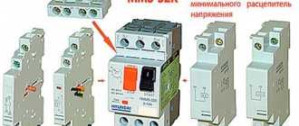
Automatic circuit breaker with independent release - what are its advantages?
The independent release is an addition to the protective device for the electrical network. It is mechanically connected to the circuit breaker. An independent release performs the function of breaking the circuit when factors are detected that can lead to damage to the line and the devices included in it. These include an increase in current strength above the limit that the cable can withstand, a breakdown of electric current to the ground or the body of a device connected to the circuit, as well as a short circuit. This material will help you understand what circuit breaker releases are, what types of this device there are and what the operating principle of each of them is. In addition, we will tell you how to check the functionality of these elements.
Limiting the duration of the control pulse and monitoring integrity.
If the independent release is connected according to a circuit where the coil is disconnected from the control circuit after activation, then an “Alarm” signal will appear in the fire alarm system as a result of a break in the control circuit.
To avoid this, it is necessary to connect the release coil directly to the PPU, bypassing additional contacts. After all, the activation time of the fire alarm output can be limited when configuring the system.
Perhaps the signal generated by a break will be sufficient to diagnose an emergency situation and there is no need to use an additional signal contact.
Both a break in the control circuit and a physical shutdown of the machine will cause the same “Alarm” signal.
I don’t know if it’s possible to make such a generalization based on GOST R 53325-2012, which says:
7.6.4.1 The device must ensure that the light indication and sound alarm are turned on in the “Fault” mode in the presence of the following events: - detection of a violation of the integrity (break, short circuit) of wired communication lines or a violation of communication between the device and external technical means or between components of the device; Note - It is acceptable that information about a fault in a wired alarm control panel of an addressless control panel is not displayed after receiving information about a fire from this alarm system. — loss or decrease below the permissible value of the power supply voltage at any power supply input; — receiving a fault signal from external technical means interacting with the device; — absence of signals confirming the activation of fire protection means after their activation by the device (in accordance with the operating algorithm of the device); — identification of malfunctions of individual components or units of the device (if the device has a self-test function). 7.6.4.2 Light indication in the “Fault” mode should be carried out by turning on the generalized yellow “Fault” indicator. Interpretation of the direction and type of malfunction should be carried out by yellow single “Fault” indicators in the directions or displayed on the SOTI. Notes 1 Information about the detection of a break or short circuit in a wired communication line may be combined into general information about the malfunction of a given communication line. 2 It is allowed to display information about the malfunction of components or units of the device and software failure using separate generalized single indicators. 3 It is allowed that there is no additional display on the SOTI of information about a power supply fault on the power supply inputs if there are separate indicators displaying the status of each input. 7.6.4.3 Information about the direction and type of fault displayed on the ICT shall be available directly or upon request. 7.6.4.4 Resetting the light indication and sound alarm about a malfunction in devices that have a device for recording and storing event data can be carried out automatically after the malfunction is eliminated. In this case, it must be ensured that information about the registered fault is stored in the recording device. Otherwise, automatic reset of the light indication and sound alarm about a malfunction is not allowed.
Features of operation of network protection circuit breakers
Whatever class the circuit breaker belongs to, its main task is always the same - to quickly detect the occurrence of excessive current and de-energize the network before the cable and devices connected to the line are damaged.
Currents that may pose a danger to the network are divided into two types:
- Overload currents. Their appearance most often occurs due to the inclusion of devices in the network, the total power of which exceeds what the line can withstand. Another cause of overload is a malfunction of one or more devices.
- Overcurrents caused by short circuit. A short circuit occurs when the phase and neutral conductors are connected to each other. In normal condition they are connected to the load separately.
The design and principle of operation of the circuit breaker is on video:
Overload currents
Their value most often slightly exceeds the rating of the machine, so the passage of such an electric current through the circuit, if it does not drag on for too long, does not cause damage to the line. In this case, instantaneous de-energization is not required in this case; moreover, the electron flow often quickly returns to normal. Each AV is designed for a certain excess of electric current at which it is triggered.
The response time of the protective circuit breaker depends on the magnitude of the overload: if the norm is slightly exceeded, it can take an hour or more, and if it is significant, it can take several seconds.
A thermal release, the basis of which is a bimetallic plate, is responsible for turning off the power under the influence of a powerful load.
This element heats up under the influence of a powerful current, becomes plastic, bends and triggers the machine.
Short circuit currents
The flow of electrons caused by a short circuit significantly exceeds the rating of the protective device, causing the latter to immediately trip, cutting off the power. An electromagnetic release, which is a solenoid with a core, is responsible for detecting a short circuit and immediate response of the device. The latter, under the influence of overcurrent, instantly affects the circuit breaker, causing it to trip. This process takes a split second.
However, there is one caveat. Sometimes the overload current can also be very large, but not caused by a short circuit. How is the device supposed to determine the difference between them?
In the video about the selectivity of circuit breakers:
Here we smoothly move on to the main issue that our material is devoted to. There are, as we have already said, several classes of AB, differing in time-current characteristics. The most common of them, which are used in household electrical networks, are devices of classes B, C and D. Circuit breakers belonging to category A are much less common. They are the most sensitive and are used to protect high-precision devices.