Key Features:
- Attenuation coefficient, dB/km - depends on the properties of the conductor materials and insulating material. Copper and silver have the best properties (low resistance). The attenuation coefficient also depends on the geometric dimensions of the conductors.
- Propagation speed, km/ms - with increasing frequency, the propagation speed increases, approaching the speed of light in a vacuum of 300 km/ms. This parameter also depends on the properties of the dielectric used in the cable.
- Crosstalk at the near end (Near End Cross Talk, NEXT);
- Characteristic resistance (impedance) (Ohm) - the resistance that an electromagnetic wave encounters when propagating along a homogeneous line without reflection, i.e. provided that the transmission process is not affected by inconsistencies at the ends of the line. The characteristic impedance of a symmetrical cable depends on the specific values of capacitance and inductance of the cable.
- Active resistance is the resistance to direct current in an electrical circuit. Unlike impedance, active resistance does not depend on frequency and increases with cable length.
- Capacitance is the property of metal conductors to accumulate energy. Two electrical conductors in a cable, separated by a dielectric, form a capacitor capable of storing charge. Capacitance is an undesirable quantity, so you should try to keep it as small as possible (sometimes the term "stray capacitance" is used). High capacitance in a cable causes signal distortion and limits the bandwidth of the line.
- Electrical noise is unwanted alternating voltage in a conductor. Electrical noise comes in two types: background and pulsed. Electrical noise can also be divided into low, medium and high frequency. Sources of background electrical noise in the range up to 150 kHz include power lines, telephones and fluorescent lamps; in the range from 150 kHz to 20 MHz - computers, printers, copiers; in the range from 20 MHz to 1 GHz - television and radio transmitters, microwave ovens. The main sources of pulsed electrical noise are motors, switches and welding units. Electrical noise is measured in millivolts.
- The diameter or cross-sectional area of a conductor.
Coaxial cables
Fifteen to twenty years ago, when creating networks, it was mainly coaxial cable that was used, consisting of a transmitting signal of a copper or aluminum core, an insulation layer, a shielding braid of copper wires or aluminum foil and a protective outer winding.
A coaxial cable used a central core to carry the signal, while the braid was grounded to act as an “electrical zero.”
Cables are graded according to the Radio Guide scale. The most common cable categories:
- RG-8 and RG-11 - “Thick Ethernet” (Thicknet), 50 Ohm. Standard 10BASE5;
- RG-58 - “Thin Ethernet” (Thinnet), 50 Ohm. 10BASE2 standard:
- RG-58/U - solid center conductor,
- RG-58A/U - stranded center conductor,
- RG-58C/U - military cable;
- RG-59 - television cable (Broadband/Cable Television), 75 Ohm. Russian analogue of RK-75-x-x (“radio frequency cable”);
- RG-6 - television cable (Broadband/Cable Television), 75 Ohm. RG-6 category cable has several varieties that characterize its type and material. Russian analogue of RK-75-x-x;
- RG-62 - ARCNet, 93 Ohm
A thin coaxial cable - flexible, with a diameter of about 0.5 cm, allows you to transmit data without attenuation over distances of up to 185 m (in real networks even up to 300 m).
To connect the cable to network devices, special BNC type connectors were used.
Simple BNC connectors were mounted at the ends of the cable sections. These sections were spliced using BNC I connectors, and BNCT connectors were used to connect to network adapters and devices.
In order for the reflected signal to be absorbed at the ends of the cable, BNC terminators were installed there, one of which was necessarily grounded. The widespread use of networks built on the basis of coaxial cable was caused by two circumstances: low cost (especially for networks on thin coaxial cable) - the cost of cable and connectors was minimal, and nothing more was required for small networks, and simplicity - it was enough to lay main cable, install terminators at its ends and connect all computers to it - and the network is ready.
Coaxial network cable
The oldest type of cable, which is practically not used in modern computer networks, is a coaxial network cable. Its extinction is due to the high cost and low data transfer speed, however, if you decide to lay a network of coaxial cable, then the most successful would be to implement it with a “bus” topology. Star and passive star topologies are also good choices.
A coaxial network cable consists of two cores: the central core is solid copper (in a very rare standard, multi-core and/or made of alloys, copper with silver plating), which is represented by the core of the cable, wrapped in thick insulation - dielectric, it is polyethylene foam.
Along this insulation there is a weaving of the so-called “external” conductor, which consists of copper, its alloy or aluminum. It is also referred to as a screen. In this case, there may be varieties of cable with a double screen, when one weave is separated from the other by an additional thin layer of insulation.
The protective sheath of the outer conductor is made mainly of polyethylene or polyvinyl chloride, which is resistant to ultraviolet radiation, but there are expensive cables with a Teflon sheath.
The types of coaxial cable are varied and there are many of them, but specifically coaxial cable for a local network differs in two standards for packet data transmission:
- 10BASE-5 (categories RG-11 and RG-8);
- 10BASE-2 (categories RG-58/U, 58A/U).
The 10BASE-5 standard is implemented using a “thick Ethernet” cable, having a total cross-section of 12 mm and a thick solid conductor core, the 11th category has a resistance of 75 Ohms, the 8th - 50. Cables of this standard could transmit data at a speed of 10 Mbit/ sec at a distance of up to 500 m.
The 10BASE-2 standard is implemented using a “thin Ethernet” cable, up to 6 mm in diameter, with a resistance of 50 Ohms. Its category RG-58/U has a solid (solid) copper center conductor, 58A/U is presented with a stranded center conductor. The data transmission length of cables of these categories is within 185 m with a maximum data transmission speed of up to 10 Mbit/s.
The advantages of coaxial cable include its effective shielding, which allows it to be carried over long distances and eliminates interference, as well as its high strength, which reduces the risk of mechanical damage to the cable. In addition, the coaxial cable is easy to install; you can attach plugs, doubles and other parts with ordinary hand tools.
The disadvantages of coaxial cable are its low throughput when used in local computer networks; against this background, a significant disadvantage is the high cost of the cable itself and plugs/doubles/adapters and other components. Plus, network cards for this type of cable are practically no longer produced; switches and hubs for them are considered obsolete.
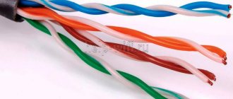
Twisted pair cables
pair is a type of communication cable that consists of one or more pairs of insulated conductors, twisted together (with a small number of turns per unit length), covered with a plastic sheath.
Purposes of twisting conductors:
- increasing the connection of conductors of one pair (electromagnetic interference equally affects both wires of the pair);
- reducing electromagnetic interference from external sources;
- reducing mutual interference when transmitting differential signals.
Types of twisted pair cables:
- unprotected twisted pair (UTP - Unshielded twisted pair) - there is no protective shield around an individual pair;
- foil twisted pair (FTP - Foiled twisted pair) - also known as F/UTP, there is one common external shield in the form of foil;
- protected twisted pair (STP - Shielded twisted pair) - there is protection in the form of a screen for each pair and a common external screen in the form of a mesh;
- foil shielded twisted pair (S/FTP - Screened Foiled twisted pair) - an external screen made of copper braid and each pair in a foil braid;
- unprotected shielded twisted pair (SF/UTP - Screened Foiled Unshielded twisted pair) - double external shield made of copper braid and foil, each twisted pair without protection.
Categories of twisted pair cables
Due to its low cost, ease of installation and versatility, it can be used in most network technologies; unshielded twisted pair is now the most common type of cable used in building local networks. Shielded twisted pair, despite its greater noise immunity, is not widely used due to installation difficulties - it is necessary to take care of grounding, and the cable is more rigid compared to unshielded twisted pair.
The twisted pair cable is connected to the computer and other devices using an eight-pin 8P8C (8 Position 8 Contact) connector. This connector is similar to those used in telephone lines (RJ-11 connector), only slightly larger and is called RJ-45.
Twisted pair cable termination into the 8P8C connector is carried out in accordance with EIA/TIA568A and 568B standards.
The twisted pair cable is inserted into the 8P8C connector using a special crimping tool - a crimper.
Note that the cables used to connect computers to hubs and switches are crimped equally on both sides, i.e. to the same standard. This produces a so-called straight cable. However, a crossover cable (“crossover cable”) is used to directly connect computer network adapters.
Twisted pair network cable
The modern and most commonly used cable for local computer networks is twisted pair cable. It is used in both home and administrative local networks with a star topology and has an excellent price/quality ratio. That is, a network cable for a local network of this type has a relatively high data transfer speed in relation to a coaxial cable, and their cost is not high.
A twisted pair network cable for local networks consists of four pairs of monolithic copper conductors, each with a cross-section of 0.4-0.6 mm. The thickness of the core of such a cable is 0.51 mm, taking into account the thickness of the conductor insulation - 0.2 mm. The insulation material used in budget versions of the cable is polyvinyl chloride (designation - PVX), in more expensive cables polypropylene and polyethylene are used (designations - PP and PE) and the highest quality twisted pair cables are made with foamed polyethylene or Teflon insulation.
According to the degree of protection against interference, there is an unshielded cable and a shielded twisted-pair cable. Shielding can be made of wire mesh, aluminum foil/aluminized film, both individual pairs and the entire bundle together.
There are cables with the following types of shielding:
- twisted pair cable (UTP) not protected by any shield at all;
- unprotected by a common shield with pair shielding with foil (U/STP);
- with foil overall shield without shielding individual pairs (FTP);
- with wire screen of each pair and common screen wire (STP);
- with a foil screen for each pair and a common braided screen (S/FTP);
- with double overall screen made of braided wire and foil (SF/UTP).
At the same time, “TP” is present in all designations - this indicates the type of cable - twisted pair (from English - twisted pair). Those letters that go ahead actually indicate the presence/absence of shielding, the type of shielding, as well as the material from which the shielding is made. Thus, the letter U (Unshielded) indicates the absence of screen protection, F (Foiled) - indicates the presence of a common foil general screen insulation of the entire bundle of pairs, S (Shielded) - a screen in the form of wire braiding of each individual pair, and (Screening) - a screen in the form braids of the entire bundle of twisted pairs.
Depending on the length and signal transmission speed, there are different categories of twisted pair (7 in total), while the intended cable for local computer networks starts from the second category, but today cables from category 5E are used starting.
The main difference between the categories of twisted pair cables was previously the number of cores, but starting from the third category and up to the seventh inclusive, all cables have four pairs (8 cores). So, the main difference was the number of turns per unit length, cross-section of the core and resistance, which is a decisive factor on the length and speed of data transfer.
Modern twisted pair cables are used in the following packet data transmission technology standards:
- 100BASE-TX Ethernet;
- 1000BASE-T Ethernet;
- 10GBASE-T Ethernet;
- 40GbE, 100GbE.
The 100BASE-TX standard was implemented using CAT cable. 5 (twisted pair category 5), which was capable of transmitting 100 Mbit/s over two pairs and 1 Gbit over four.
The 1000BASE-T standard is by far the most widespread and is used in many local computer networks. For such networks, the most popular category of cable is used - CAT. 5e, the difference from the previous one is a slightly higher throughput of high-frequency signals and the presence of modifications with two (100 Mbit/s) and four (1 Gbit) pairs.
The 10GBASE-T standard , on which Fast Ethernet and Gigabit Ethernet networks are built, is implemented using CAT cable. 6, which is capable of transmitting data at a speed of 10 Gbit/s over a distance of 55 m. Gigabit Ethernet can also be implemented on CAT cable. 6a and CAT. 7, which increases the data transmission length to 100m. In this case, the seventh category always has full shielding.
The 40GbE and 100GbE standard are the most modern and high-speed packet data technologies that are designed for a Gigabit Ethernet network with a CAT cable. 7a. At a data transfer rate of 40 Gbit/s, the transmission length is 50 m, at 100 Gbit/s – 15 m.
Fiber optic communication lines
Fiber-optic communication lines (FOCL) have a number of significant advantages compared to communication lines based on metal cables:
- high throughput;
- low attenuation;
- small weight and dimensions;
- high noise immunity;
- reliable safety equipment;
- practically no mutual influences;
- low cost due to the absence of non-ferrous metals in the design.
FOCLs use electromagnetic waves in the optical range. Let us recall that visible optical radiation lies in the wavelength range 380...760 nm. The infrared range has received practical application in fiber-optic communication lines, i.e. radiation with a wavelength greater than 760 nm. Several types of waves (modes) can exist simultaneously in an optical waveguide. Depending on the mode characteristics, optical fiber is divided into two types:
- multimode
- single-mode
A fiber optic cable consists of a central light conductor (core), a glass fiber, surrounded by another layer of glass, a cladding that has a lower refractive index than the core. Spreading throughout the core, light rays do not go beyond its boundaries, reflecting from the covering layer of the shell
The following are used as light sources in fiber optic cables:
- LEDs;
- semiconductor lasers.
Depending on the distribution of the refractive index and the size of the core diameter, the following are distinguished:
- multimode fiber with a step change in refractive index. In a stepped optical fiber, up to a thousand modes with different distributions over the cross-section and length of the optical fiber can be excited and propagated. The modes have different optical paths and therefore different propagation times along the fiber, causing the light pulse to broaden as it travels through the fiber. This phenomenon is called mode-to-mode dispersion and it directly affects the speed of information transmission along the optical fiber.
- multimode fiber with a smooth change in refractive index. It differs from stepwise in that the refractive index of the core smoothly increases from the edge to the center. This leads to the phenomenon of refraction in the core, thereby reducing the influence of intermode dispersion on the distortion of the optical pulse. The refractive index profile of the gradient fiber can be parabolic, triangular, broken, etc.
- single mode fiber. In this optical fiber, only one mode exists and propagates (more precisely, two degenerate modes with orthogonal polarizations), so there is no inter-mode dispersion, which allows signals to be transmitted over a distance of up to 50 km at speeds of up to 2.5 Gbit/s and higher without regeneration.
To connect the optical cable, special connectors are used. SC and ST connectors are considered obsolete today, so FC connectors are most often used in new equipment.
ST and SC connectors have the simplest design and can be used both in backbone networks and in patch cords. They use a push-pull connection mechanism. Unfortunately, their prostate negatively affects reliability.
The FC connector is more reliable because it has a ceramic tip and a union nut to secure the connector to the optical port. This makes it possible to use it not only in backbone networks, but even in conditions of high mobility.
Installation of connectors (embedding a fiber optic cable into a connector) is quite complicated and requires special equipment. However, recently kits have appeared that allow you to seal such connectors at home. However, their use requires precision and patience, as they are made by gluing an optical fiber into a tip and then drying it with a fine grind.
Compared to electrical cables, optical fiber provides unsurpassed noise immunity and protection of the transmitted signal from interception. In addition, when using it, data can be transmitted over significantly longer distances, and the theoretically possible transmission speeds in optical fiber are much higher.
Fiber Transparency Windows
Transparency window is a wavelength range of optical radiation in which there is less attenuation of radiation in the medium, in particular in optical fiber, compared to other ranges. Standard stepped optical fiber SMF has three transparency windows: 850 nm, 1310 nm and 1550 nm. To date, the fourth (1580 nm) and fifth (1400 nm) transparency windows have been developed, as well as optical fibers that have relatively good transparency throughout the near-infrared range.
Initially, in the 70s, fiber optic communication systems used the first transparency window, since the GaAs lasers produced at that time operated at a wavelength of 850 nm. Currently, due to high attenuation, this range is used only in local networks.
In the 80s, lasers based on ternary and quaternary heterostructures were developed, capable of operating at a wavelength of 1310 nm, and the second transparency window began to be used for long-distance communications. The advantage of this range was zero dispersion at this wavelength, which significantly reduced the distortion of optical pulses.
The third window of transparency was mastered in the early 90s. The advantage of the third window is not only the minimum loss, but also the fact that the operating range of erbium fiber amplifiers (EDFA) falls at the wavelength of 1550 nm. This type of amplifier, having the ability to amplify all frequencies of the operating region, predetermined the use of the third transparency window for wavelength division multiplexing (WDM) systems.
The fourth transparency window extends to a wavelength of 1620 nm, increasing the operating range of WDM systems.
The fifth window of transparency appeared as a result of thorough cleaning of the optical fiber from foreign impurities. Thus, AllWave optical fiber was obtained, which has low losses throughout the entire region from 1280 nm to 1650 nm.
DIY optical S/PDIF for PC
Digital interfaces have long been pushing aside their analog ancestors. Middle-class audio systems use sound encoded in one of many standards as a signal source. This could be banal PCM for stereo sound or the Dolby family of standards for their multi-channel relatives. But today we will not talk about encoding methods, but about how exactly the signal is transmitted. There are only two options - optical and coaxial cable. The optics guarantee complete electrical isolation, the coaxial cable is easy to connect. For ten years now, almost every motherboard has been equipped with an optical digital output S/PDIF (aka TOSLINK). But if you look at the back panel you can’t always find it. What's the catch? The manufacturer does not want to install another connector on the rear panel and increase the cost of the board by installing an optical module or a socket for a coaxial cable. If you open the documentation for the motherboard, you will find a typical set of four contacts similar to a socket for connecting a speaker.
On the same page there is a branded bracket with coaxial and optical outputs. Sometimes there are also optical inputs, but the author of the article only read about this on the Internet. Finding an original plank can turn into a non-trivial task - the price at foreign auctions is about $10, excluding delivery. A quick search on Russian-speaking forums finds only requests for its purchase and advice to buy a sound card with the appropriate socket instead.
So, we’ll make the bar ourselves. Despite the potential ease of manufacturing, nothing similar was found on the network for an optical connection. There is more information on coaxial connection - but we want optics. So we start reading the documentation, for example here, S/PDIF Documentation.
According to the specification, the signal level on the motherboard is TTL; we can only guess about the load capacity of the SPDIFOUT output. The same documentation recommends loading it with an LED with a current-limiting resistor - this will be the cheapest connection. I didn’t dare try this option first for two reasons - I felt sorry for the board and the urgent need to plug a standard optical cable somewhere. Later, I nevertheless assembled an emitter follower on one transistor and connected an LED. The interface glowed cheerfully with a red LED, but the optical cable attached to it did not produce sound. The same documentation recommended choosing an ultra-bright LED with a wavelength of 660 nanometers. Perhaps none of the LEDs used were suitable.
The next step is to connect the recommended TOTX173 optical module. The price and availability in online stores are again not encouraging - a little less than the same ten dollars and long delivery. So it's time to look for a donor. After going through the electronics dump at home, we were able to identify only one victim; it turned out to be a Playstation 2, a gift from employees for their last birthday. No hand was raised against the vandalism of the legendary console. At a regional online auction, a Samsung DVD Recorder was caught for the same sacred $10 without delivery. Photos will follow.
S/PDIF on the victim looked like this
Since a search using the code on the case (T2002H7) did not yield anything, the device had to be turned on in a disassembled state to make sure that it was using a five-volt power supply and a TTL signal level.
There are only three contacts, the common one is easily identified, the power is connected directly to the signed 5V plug, leaving the information output connected through a 220 Ohm resistor. Here's a close-up of our newfound module.
All that remains is to connect to the motherboard and assemble it all in the form of a bracket. We connect the common pin to common, power to power, and SPDIFOUT through a 220 Ohm resistor to data. We assemble a PC bracket from a piece of a breadboard and a burnt-out network card, this is what I did.
We install it in the case.
More than two weeks have passed since assembly - everything works perfectly. By ear, of course, the difference is within the limits of the sensations given by psychology. But if there is acoustics that understands optics, why not use a connection made by yourself. In the comments, it would be interesting to hear an opinion about the possible difference in the sound of such an optical output and that obtained from a mid-price range sound card.
After assembly, I made my way to the nearest appliance repair shop. It was there that we should immediately look for a donor - they have a sufficient number of burnt-out DVD players, for about a dollar per fee. For those who want to repeat the design, this will be useful.