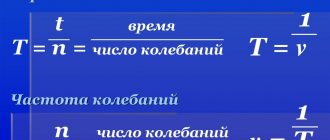
Discovery of the Hall effect
The future physicist Edwin Herbert Hall was born in the American city of Gorham in 1855. Having received his primary education, he entered the university in 1875, where he conducted his first experiments. So, while studying Maxwell's works on electricity and magnetism, Hall became interested in two facts.
The first was that the forces arising in a conductor located transverse to the lines of magnetic induction are applied directly to the substance. The second reported that the value of these forces depends on the speed of movement of the charges. In 1879, the scientist Edmund Hall published an article proving the fact that a magnetic field acts with the same force on both a suspended and a fixed object.
Analyzing what force can control the movement of charged particles, he came to the conclusion that it can only be voltage. For the first experiment, the physicist used a wire bent into a spiral and sandwiched between dielectrics. He placed this structure between two magnets and powered it from a chemical current element. A Wheatstone bridge with a Kelvin galvanometer was used as a recorder. In total, about thirteen experiments and more than four hundred measurements were carried out under different conditions. The results of the experiments were the statement that magnetic flux can change the resistance of a material.
On the advice of Professor Rowland, the direction of a new experiment was developed, concluding as follows:
- An electric current was supplied to the conducting plate.
- The galvanometer was connected to the edges of the conductor.
- The electromagnet was turned on so that the field strength lines lay perpendicular to the plane of the plate.
It was supposed to discover the conditions for changing the flow of current. But the experiment did not work until they tried to use a thin sheet of gold as a plate. The new experiment was successful. The galvanometer clearly recorded the voltage that appeared.
As a result, it was discovered that when an electric current is applied to a conductor, the charge in it is distributed evenly over its entire surface.
But as soon as a magnetic field is applied to the plate, the induction lines of which are perpendicular to the direction of the current, the charge is redistributed to the edges, and a potential difference arises. This is the Hall effect, on the basis of which sensors of the same name were later built.
First Hall sensor
The first Hall sensor was designed by Professor Rowland. In the same form in which the device is used today. Seeing that Edwin's experiments (and his own) did not lead to results, the lecturer proposed an old model of an experiment done years earlier (the design of the Hall sensor is described):
- A conductive disk (or a plate of another shape) is included in the electrical circuit.
- Using a galvanometer, two equipotential points are located on the sides of the figure.
- An electromagnet is turned on, the field strength lines of which lie in a plane perpendicular to the disk.
- Changes in galvanometer readings are recorded.
It was supposed to detect signs of changes when the conditions of current flow change. The experiment used a Hall sensor in its current version, but the experiment was unsuccessful. It is generally accepted that too much disk thickness is to blame. The professor brought this to the attention of Edwin and expressed the opinion that the situation could be corrected if a thin gold sheet mounted on a glass base was used (to prevent the metal from being deformed by the field). The experiment carried out on October 28 was completely successful; it was possible to record a stable deflection of the galvanometer needle under the influence of a magnetic field on a current-carrying plate.
And although the movement turned out to be permanent and quickly disappeared, this could not be attributed to magnetic induction (from Faraday’s experiments). The error introduced by the field of electric solenoids was quickly eliminated. A discovery was clearly looming on the horizon. It is remarkable that when the polarity of the magnet was changed, the effect was inverted. To establish quantitative dependencies, the apparatus was slightly improved:
- Strong contact of the power source was ensured on each side by brass plates, well polished and carefully soldered to gold (9x2 cm).
- There was pure metal left in the center: an area 5.5 cm long and across the entire width. Here, magnetic field lines ran through the gold.
- The contacts of the high-resistance Thomson galvanometer fit along the edges, equidistant from the brass plates.
Hall measurements results
During the experiment, the magnetic field of the solenoids, currents through the plate and galvanometer were measured. The result was presented in the form of a table, shown in the figure, showing that Edwin Hall managed to obtain the first patterns. This happened on November 12, 1879. Even though the expression on the right has values that differ by 8%, it is clear that the order of the numbers is the same. And we will attribute the deviations to errors of experimenters and equipment.
Exact values are not always important. Today, Hall sensors are actively used as indicators of the absence or presence of a magnetic field. For example, in keyboards or washing machine motors.
Physical and mathematical definition
The Hall effect is a phenomenon that can be observed when a substance that conducts electric current is placed under the influence of a magnetic field. Physicist Hall discovered that in a conductor, when a direct current is passed through it, an electromotive force (EMF) appears if it is placed in a transverse magnetic field. Physically, this means the appearance of voltage on the side faces of a conductive substance when a magnet is brought close to it. Using this, magnetic radiation can be detected. The resulting tension depends on three factors:
- current strength;
- field strength;
- type of conductor.
You might be interested in The design of a thermocouple, its types and operating principle
The force with which an electromagnetic field acts on a point charge in a substance is called the Lorentz force. A special case of it is the Ampere force. Mathematically, the electric field strength is described by the expression:
E h = R*H*j*sinα, where:
- H—magnetic field strength;
- j is the current density;
- α is the vector angle between the field lines H and j;
- R is Hall's constant.
If a current is supplied to a rectangular plate having a length L, which will greatly exceed the width b and thickness d, then its value will be determined by the formula: I = j*b*d. When it is moved into a magnetic field directed perpendicular to this current, an emf will appear on the side faces of the plate equal to:
V h = E h* b = R*H*I/d.
Since the effect is explained by the influence of the field on elementary particles (holes or electrons), the force acting on them is described by the Lorentz law: F =e * [H*υ], where υ is the average speed of charge carriers, depending on the concentration and size of the carriers. Under the influence of this force, the carriers begin to be pressed against the side surfaces of the plate perpendicular to j and H. There they accumulate, and the Hall phenomenon occurs, balancing the Lorentz force.
In this case, the Hall coefficient is equal to: R = 1/n*e. For example, for metals it is about 10-3 cm3/C, and for semiconductors from 10 to 105 cm3/C.
The Hall constant can also be expressed in terms of the ability of charge carriers to respond to external influences (mobility). So, it is equal to: R = µ/σ, where: µ is the drift velocity of carriers, and σ is the electrical conductivity. But this is more true for polycrystals. At the same time, for anisotropic conductors the formula will be more accurate: R = r/e*n. Here r is taken equal to one and denotes an estimate of the magnetic field strength.
Theory
Qualitative picture of the phenomenon
Installation for measuring the Hall effect for electrons. Initially, the electrons move in a curved arrow due to the magnetic force (Lorentz force). At some distance from the current-carrying contacts, electrons accumulate on the left side and escape from the right side, which creates an electric field ξy
in the direction of a given
VH
The VH
voltage is negative for some semiconductors where "holes" appear to flow.
In steady state, ξy
will be strong enough to exactly cancel out the Lorentz force, so the electrons move along, on average, along a broken straight arrow.
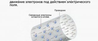
The Hall effect is associated with the nature of current carriers in a conductor. Current is thought of as the directed movement of many tiny charge carriers, usually electrons—negatively charged particles, but other quasiparticles—holes—that carry a positive charge can also appear in a solid. In the presence of a magnetic field, moving charges experience a force called the Lorentz force[8]. When such a magnetic field is absent, charges follow approximately straight paths between collisions with impurities, phonons, and other defects. The time between collisions is called the free path time[9]. When a magnetic field with a component perpendicular to the direction of the current is applied, their paths between collisions are bent, such that in the final sample, charges of a certain sign accumulate on one of its sides, and a charge with the opposite sign accumulates on the other side. The result is an asymmetric distribution of charge density across the sample, resulting from a force perpendicular to both the direction of the current and the applied magnetic field. The separation of charges of opposite sign creates an electric field that prevents diffusion and further accumulation of charge at the boundaries of the sample, therefore a constant electric potential is established while current flows [10].
In classical electromagnetism, electrons move in the direction opposite to the direction of current I
(by convention, “current” describes the theoretical flow of positively charged particles).
In some metals and semiconductors , positively charged particles—
"holes"—seem to flow because the sign of the Hall voltage is opposite to that shown below for electrons.
Play media file
An animation demonstrating a simple principle.
For a simple metal in which there is only one type of charge carrier (electrons), the Hall voltage V
H is obtained using the Lorentz force and the condition that in a stationary state the charges should not move along the
y
.
Thus, the magnetic force acting on each electron in the y-axis direction is
compensated by the electric field along the
y
-axis due to the accumulation of charges.
The term vx
is the drift velocity of the current, which at this point is by convention considered a hole.
The term vxBz
is negative in the
y
-axis direction according to the right-hand rule.
F = q ( E + v × B ) {\displaystyle \mathbf {F} =q{\bigl (}\mathbf {E} +\mathbf {v} \times \mathbf {B} {\bigl )}}
B steady state F
=
0
, so 0 =
Ey
−
vxBz
, where
Ey
is given in the
y
(not with the induced electric field arrow
ξy
as in the image (pointing in the −
y
), which tells where the electron-induced field is pointing).
The wires are leaking electrons instead of holes, so replacements need to be made vx
→ −
vx
and
q
→ −
q
.
Also Ey
= −
V
H
w
VH = vx B zw {\displaystyle V_{\mathrm {H} }=v_{x}B_{z}w}
The usual "hole" current is directed in the negative direction of the electron current and negative electric charge, which gives Ix
=
ntw
(−
vx
)(−
e
) where
n
is the charge carrier density,
tw
is the cross-sectional area, and −
e
is the charge of each electron.
Solving for w {\displaystyle w} and substituting into the above expression gives the Hall voltage: VH = I x B znte {\displaystyle V_{\mathrm {H} }={\frac {I_{x}B_{z}}{nte }}}
If the charge accumulation were positive (as in some metals and semiconductors), then the value of V
H in the image would be negative (a positive charge would form on the other side, the left side).
The Hall coefficient is defined as
RH = E yjx B z {\displaystyle R_{\mathrm {H} }={\frac {E_{y}}{j_{x}B_{z}}}} or E = − RH ( J c × B ) {\displaystyle \mathbf {E} =-R_{\mathrm {H} }(\mathbf {J} _{c}\times \mathbf {B} )}
where j
is the current density of carrier electrons, and
Ey
is the induced electric field.
In SI units this can be written as RH = E yjx B = VH t IB = 1 ne .
{\displaystyle R_{\mathrm {H} }={\frac {E_{y}}{j_{x}B}}={\frac {V_{\mathrm {H} }t}{IB}}={ \frac {1}{ne}}.} (Units R
H is usually expressed in m3/C, Ohm cm/ or other variants. As a result, the Hall effect is very useful as a means of measuring charge carrier density or the magnitude and direction of a magnetic field.
One very important feature of the Hall effect is that it distinguishes between positive charges moving in one direction and negative charges moving in the opposite direction. The diagram above shows the Hall effect with negative charge carriers (electrons). But if, under the same conditions: magnetic field and current, we use a different sign of the current carriers, then the Hall effect will change sign. Of course, the particle must move in the opposite direction of the electron for the current to be the same - down on the diagram, not up like the electron. And thus, mnemonically speaking, your thumb in the Lorentz force law, representing the (conventional) current, will point in the same
direction as before because the current is the same - an electron moving up has the same current as a positive charge moving down.
And with the same fingers (magnetic field), the charge carrier is deflected to the left in the diagram, regardless of whether it is positive or negative.
But if positive carriers are deflected to the left, they create a relatively
positive voltage
on the left, while negative carriers (namely electrons) create a negative voltage on the left, as shown in the diagram. Thus, for the same current and magnetic field, the polarity of the Hall voltage depends on the internal nature of the conductor and is useful for elucidating its charge properties.
This property of the Hall effect provided the first real evidence that electric currents in most metals are carried by moving electrons rather than protons. He also showed that in some substances (especially p-type semiconductors), on the contrary, it is more appropriate to think of the current as moving positive "holes" rather than as negative electrons. A common source of confusion with the Hall effect in such materials is that holes moving in one direction are actually electrons moving in the opposite direction, so the polarity of the Hall voltage can be expected to be the same as if the electrons were carriers charge, as in most metals and n-type semiconductors. However, the opposite polarity of the Hall voltage is observed, indicating that the charge carriers are positive. However, of course, in p-type semiconductors there are no real positrons or other positive elementary particles that carry charge, hence the name "hole". Just as the overly simplified picture of light in glass as photons absorbed and re-emitted to explain refraction collapses on closer inspection, this apparent contradiction can also only be resolved by modern quantum quasiparticle theory, in which the collective quantized motion of multiple particles is possible. in a real physical sense, considered as a separate particle (although not elementary)[11][ clarify
].
Unrelated to this, inhomogeneity in a conductive sample can lead to a false Hall effect signature even with an ideal van der Pauw electrode configuration. For example, the Hall effect, corresponding to positive carriers, was apparently observed in n-type semiconductors[12]. Another source of artifacts in homogeneous materials occurs when the aspect ratio of the length to width of the sample is not large enough: the full Hall voltage occurs only away from the current-carrying contacts, since the transverse voltage is shorted at the contacts.
Hall effect in semiconductors
When a current-carrying semiconductor is in a magnetic field, the charge carriers of the semiconductor experience a force in a direction perpendicular to both the magnetic field and the current. In a state of equilibrium, a Hall voltage appears at the edges of the semiconductor.
The simple formula for the Hall coefficient above is usually a good explanation when conduction is dominated by a single charge carrier. However, for semiconductors and many metals the theory is more complex because in these materials conductivity may involve significant simultaneous contributions from both electrons and holes, which may be present in different concentrations and have different mobilities. For moderate magnetic fields, the Hall coefficient[13][14] is calculated using the formula
RH = p μ h 2 − n μ e 2 e ( p μ h + n μ e ) 2 {\displaystyle R_{\mathrm {H} }={\frac {p\mu _{\mathrm {h} }^ {2}-n\mu _{\mathrm {e} }^{2}}{e(p\mu _{\mathrm {h} }+n\mu _{\mathrm {e} })^{2 }}}}
or equivalent
RH = p − nb 2 e ( p + nb ) 2 {\displaystyle R_{\mathrm {H} }={\frac {p-nb^{2}}{e(p+nb)^{2}}} }
with replacement
b = μ e μ h . {\displaystyle b={\frac {\mu _{\mathrm {e} }}{\mu _{\mathrm {h} }}}.}
where n
is the electron concentration,
p
is the hole concentration,
μ
e is the electron mobility,
μ
h is the hole mobility and
e
is the elementary charge.
For large application fields, a simpler expression is valid, similar to the expression for one media type.
Quantum Hall effect
Main article: Quantum Hall effect
In strong magnetic fields in a flat conductor (that is, in a quasi-two-dimensional electron gas), quantum effects begin to affect the system, which leads to the appearance of the quantum Hall effect: quantization of the Hall resistance. In even stronger magnetic fields, the fractional quantum Hall effect appears, which is associated with a radical restructuring of the internal structure of a two-dimensional electron liquid.
Varieties of the phenomenon
As the effect was studied, a number of features of the appearance of the electric field were discovered that differed from the classical understanding. Thus, scientists have identified factors that lead to the appearance of voltage without passing current through the plate. Such phenomena are called:
- abnormal;
- quantum;
- spin.
For an anomalous effect, a necessary condition is the violation of T-symmetry, that is, the equations that describe physical laws during time reversal. This effect is most often observed in materials that have residual magnetization (ferromagnets).
Quantum deviation arises in a quasi-two-dimensional electron gas, where the Coulomb interaction is neglected. In it, charge carriers have a weak connection with the ions of the crystal lattice. The laws of quantum theories work in such a system.
Moreover, the stronger the magnetic field, the more pronounced the fractional Hall phenomenon associated with the transformation of the structure of the entire electron gas.
In 1971, scientists Dyakonov and Perel, studying the mechanism of spin relaxation, discovered that perpendicular to the direction of the electromagnetic field lines, a deflection of charge carriers with opposite spins is observed. This effect was associated with spin-galvanic scattering and the interaction between spin and orbital magnetic moments.
You might be interested in Calculation and tables for selecting cable cross-sections based on power and current
Ways to use the phenomenon
Based on the Hall effect, devices and instruments are created that have the necessary and often unique properties. These devices occupy an important place in measurement and control technology, automation, radio engineering, etc. Devices that use the Hall phenomenon in their work are called Hall elements (sensors).
These sensors make it possible to measure the strength of the magnetic field, since at a constant current value the electromotive force is directly proportional to the magnetic induction lines. The direct dependence of these quantities for Hall elements is an undeniable advantage over other types of induction meters based on monitoring magnetoresistance.
Hall devices make it possible to measure the electrical and magnetic characteristics of not only metals, but also semiconductors. Due to their simplicity of operation, ease of manufacture, as well as high accuracy and reliability, they are widely used in various branches of science and technology. Sensors are used to measure force, pressure, angles, displacement and other non-electrical quantities. This effect is also used in the manufacture of semiconductors to control the mobility of charge carriers and calculate their concentration.
For this, the Hall effect formula is used: V h = j*B*H / n*q = B*I / (q*n*α) = R*B*I/α,
from which the number of carriers is found as N = (I*B) / (q*α* V h). In this way, it is possible to determine not only the number of media, but also their type (sign).
Hall elements are used in the automotive industry due to their low cost, accuracy of readings, reliability and ability to be independent of environmental conditions. They are used in the design of contactless unipolar and bipolar breakers. Thanks to their miniature design, electronic gadgets can automatically turn on or off the screen when you open or close the magnetic case. They help in GPS navigation by improving geolocation.
Every year the Hall effect finds more and more new applications. Evidence of this is the emergence of a virtual reality device - the Google Card Board, the operation of which is based on the interaction of a magnet with a Hall sensor.
Device and examples of use
The simplest system with a Hall sensor includes the following elements:
- Permanent magnet (its function is to create a magnetic field).
- A movable rotor with blades or teeth.
- A special rod made of magnetic material (magnetic core).
- Plastic case.
In addition, the technical characteristics of the sensor provide for the use of microcircuits involved in the measurement process.
It is possible to understand the operating principle of this device if you familiarize yourself with the detailed diagram of the connection of the Hall sensor in the measurement area. The connection diagram and the essence of the sensor’s operation can be presented as follows:
- The metal rotor blades move in the gap formed by the halves of the magnetic circuit.
- When they rotate, periodic shunting of the magnetic flux occurs.
- The built-in microcircuit provides for determining the zero induction index (at these moments the voltage at its output is maximum).
- Based on the frequency of such bursts, counted by the same microcircuit, the rotation speed of the controlled object (the motor shaft in a motorcycle, for example) is judged.
For this process to proceed normally, when connecting the sensor to the measuring circuit, the pinout of the given sample must be taken into account (it can be different).
Summarizing the considered scheme, it should be assumed that sensors of this class are capable of measuring the crankshaft rotation speed of any moving vehicle. The versatility of the sensor, which does not exclude the possibility of its installation in a scooter, for example, allows the Hall sensor to be used not only in complex technical devices, but also in ordinary household appliances.
Application in ignition system and washing machines
When using a Hall sensor in a car's ignition system, it can be used to detect the moment the distributor opens. In this case, it works as an analog converter that determines when the on-board power supply is interrupted. Its use in the working modules of a washing machine is based on the same principle, which makes it possible to determine the increase in the weight of the laundry by the speed of rotation of the drum.
Hall sensors are also installed in some types of measuring equipment. Most often, they are equipped with non-contact clamps used to measure current in conductors. The built-in device responds to changes in the electromagnetic field generated around the power cable. In addition, it fits the throttle handle of an electric bicycle, allowing you to control its rotation angle.
At home
In computer keyboards, these devices provide a non-contact way to read information. The sensor included in a household PC cooler is capable of controlling the polarity of the rotor windings, that is, changing the direction of its rotation.
When using such an element in a smartphone, in particular, it ensures that the device is turned off when it is placed in a case with a “magnetic” clasp.
Considering the areas of application of Hall sensors, in simple words we can say that its use in the technical field is practically unlimited. In the electronic designer Arduino, for example, there is a kit with such a sensor, which allows you to illustrate the Hall effect in practice.
This is not the only example of its use for training purposes, helping novice users understand how to connect and use field structure sensors.
In conclusion, we note that the disadvantages of Hall sensors include their sensitivity to electromagnetic interference, which often occurs in operating circuits. In addition, the use of complex electronic modules in the design of the device to some extent affects its reliability, somewhat reducing it. These disadvantages of the sensor are not considered as its defects, but are simply taken into account when working with the equipment.
Now you know what a Hall sensor is, how it works and why it is needed. We hope the information provided was useful and interesting!
Magnetic sensors
The main advantage of using magnetic field sensors is their non-contact operation. They are analog and discrete. The first type is considered classic. It is based on the principle that the stronger the magnetic field, the greater the voltage. In modern instruments and devices, this type is practically no longer used due to its significant size. The digital sensor is built on the “key” operating mode and has two stable positions. If the induction force is insufficient, it does not work.
You may be interested in Formula for determining the electric field strength
Discrete Hall elements are divided into two types:
- unipolar - the operation of which depends on the pole of the magnetic field;
- bipolar - the sensor state switches when the magnetic pole changes;
- omnipolar - react to the action of magnetic induction in any direction.
Structurally, the sensor is an electronic device with three terminals. It can be produced either in a standard DIP, DFN or SOT version, or in a sealed version: for example, 1GT101DC (sealed), A1391SEHLT-T (DNF6), SS39ET (SOT), 2SS52M (DIP).
Device characteristics
Manufactured sensors using the Hall phenomenon, like any electronic radio components, are characterized by their own parameters. The main ones are the type of device and supply voltage. But, besides this, the following technical characteristics are distinguished:
- The magnitude of the measured induction. It is measured in gauss or millitesla.
- Sensitivity - determined by the value of the magnetic flux to which the sensor responds, the unit of measurement is mV/Gauss or mV/mT.
- Zero magnetic field voltage is the value of the potential difference corresponding to the absence of a magnetic field.
- Zero drift is a change in voltage that depends on temperature. Indicated as a percentage deviation from a temperature of 25 °C.
- Sensitivity drift is a change in sensitivity caused by a change in temperature.
- Bandwidth - level of sensitivity reduction in 3 dB steps.
- On and off induction is the field strength value at which the sensor operates stably.
- Hysteresis is the difference between the inductions of on and off;
- Response time - characterized by the time interval of transition from one stable state to another.
Manufacturing of devices
The material from which the Hall element is made must have high mobility of charge carriers. To obtain the highest voltage value, the substance should not have high electrical conductivity. Therefore, in the production of devices the following are used: selenide, mercury telluride, indium antimonide. Thin-film sensors are produced by evaporating a substance and depositing it on a substrate. It is used as mica or ceramics.
Sensors are also made from semiconductors - germanium and silicon. They are doped with arsenic or phosphorus antimony. Such devices have a low dependence on temperature changes, and the magnitude of the emf generated by them can reach one volt.
A typical manufacturing process for a Hall plate sensor consists of the following steps:
- cutting the plate to the required size;
- surface grinding;
- formation of symmetrical leads by soldering or welding;
- sealing.
Thus, the application of the Hall effect has found wide application in magnetometry, smartphones, cars, switches and security systems.
One of the main advantages of sensors made using this effect is electrical isolation (galvanic isolation), which makes their use convenient and safe.