Squirrel cage type windings
1. Design.
Squirrel cage-type squirrel-cage windings include the rotor windings of squirrel-cage asynchronous motors, damper (quiescent) windings of synchronous generators and starting windings of synchronous motors. The winding is formed from rods closed on both sides by a short circuit and rings. In asynchronous machines, an equal-pitch, or full, squirrel cage is used, in which the distances between adjacent rods are the same (Fig. 16-23). In synchronous machines (salient poles), an unequal pitch, or incomplete, squirrel cage is used, the rods of which are located, as a rule, only in the pole piece and are absent in the interpolar space (Fig. 16-24). The squirrel cages of the rotors of asynchronous motors with a power of up to 200 kW (in some cases - up to 400 kW) are made of cast aluminum (Fig. 16-23). » Pure primary aluminum is used to fill the rotors of general purpose electric motors. The chemical composition of the cast squirrel cage must correspond to the composition of primary aluminum grade A5 or A6 (no more than 0.5% impurities). Cast squirrel cages are technologically advanced and reliable. Squirrel cages with a diameter of up to 550 mm and a length of up to 700 mm are produced using the casting method. Cast squirrel cages are used, in particular, in electric motors of the single series A, AO, A2, AO2 up to size 11. The rods of cast squirrel cages are located in closed or semi-closed grooves of various shapes (deep with parallel walls, deep trapezoidal, wedge-shaped, scapular - Fig. 16-25, a-d). The short-circuited windings of large induction motors (with a power of approximately over 200 kW) and salient-pole synchronous machines are welded, usually from copper or brass rods and copper (brass, sometimes steel) short-circuit rings or segments. Welded short-circuited windings of asynchronous motors can have rods of round, rectangular (deep groove, Fig. 16-25, f) or special (flask-shaped, wedge-shaped - Fig. 16-25, e, g) profile; double squirrel cages are also used, when the rods of both windings are located in semi-closed grooves at different depths (Fig. 16-25, h). In asynchronous motors with a double squirrel cage, usually the rods of the working (inner) cage are copper, and the starting (external) cage is brass (less often, bronze). Large asynchronous motors of the A and A3 series produced by domestic industry (power from 200 to 1,250 kW) have a squirrel cage with rods of a predominantly flask-shaped profile. The squirrel cage rods of synchronous machines usually have a circular cross-section and are made of copper or brass. The rods are located in the grooves of the pole pieces. The rods of each pole are soldered on both sides to the segments, the segments of adjacent poles are connected to each other with bolts (Figure 16-24). The connection of rods with short-circuiting rings (segments) in welded squirrel cages is carried out by soldering with hard solders (mainly grades PSr-15, PSr-45 and PMF-7) using a gas welding torch. Rice. 16-23. Cast aluminum squirrel cage (ventilation blades located on short-circuiting rings are cast at the same time as the cage).
Rice. 16-24. Rotor of a synchronous machine with damper winding.
Rice. 16-25. Grooves and rods of short-circuited windings of asynchronous motors.
Rice. 16-26. To calculate e. d.s. and n. With. equal-paced squirrel cage.
Source
Three-phase squirrel-cage asynchronous motor
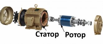
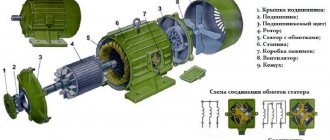
Construction of an asynchronous electric motor
Stator
consists of a body and a core with a winding. The stator core is assembled from thin sheet technical steel, usually 0.5 mm thick, coated with insulating varnish. The laminated core design contributes to a significant reduction in eddy currents arising during the process of magnetization reversal of the core by a rotating magnetic field. The stator windings are located in the slots of the core.
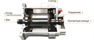
Rotor
consists of a core with a short-circuited winding and a shaft. The rotor core also has a laminated design. In this case, the rotor sheets are not varnished, since the current has a low frequency and the oxide film is sufficient to limit eddy currents.
Principle of operation. Rotating magnetic field
The operating principle of a three-phase asynchronous electric motor is based on the ability of a three-phase winding to create a rotating magnetic field when connected to a three-phase current network.
The rotation frequency of this field, or the synchronous rotation frequency, is directly proportional to the frequency of the alternating current f1 and inversely proportional to the number of pole pairs p of the three-phase winding.
,
Rotating magnetic field concept
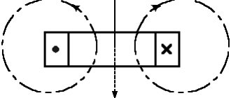
To understand the rotating magnetic field phenomenon better, consider a simplified three-phase winding with three turns. Current flowing through a conductor creates a magnetic field around it. The figure below shows the field created by three-phase alternating current at a specific point in time
The components of alternating current will change over time, causing the magnetic field they create to change. In this case, the resulting magnetic field of the three-phase winding will take different orientations, while maintaining the same amplitude.
The effect of a rotating magnetic field on a closed loop
Now let's place a closed conductor inside a rotating magnetic field. According to the law of electromagnetic induction, a changing magnetic field will give rise to an electromotive force (EMF) in the conductor. In turn, the EMF will cause a current in the conductor. Thus, in a magnetic field there will be a closed conductor with a current, on which, according to Ampere’s law, a force will act, as a result of which the circuit will begin to rotate.
The influence of a rotating magnetic field on a closed conductor carrying current
Anchor
The electrical engineering term armature usually refers to one of the parts of electrical machines that have windings. However, this term may also refer to the moving part of the magnetic circuit of a relay or electromagnet. In electric machines, the armature can be either a stator or a rotor. It all depends on the circumstances. GOST 27471-87 (Rotating electric machines. Definitions) gives the armature this designation
The part of a DC commutator machine or an AC synchronous machine in which an emf is induced and a load current flows.
Typically, in practice, the concept of armature refers to the part of the electric motor through the windings of which the electric current of the network flows during operation. That is, the armature is that part of the electric motor to the windings of which power is connected (working winding). For a generator, the armature means that part from which the generated voltage is removed. For example, in a brushed DC motor the armature is the rotor. And in a brushless DC motor, the armature will be the stator. For synchronous alternating current generators, most often the armature is the stator. Although in some low-power generators, the armature is a rotor from which the generated voltage is removed through brushes.
Asynchronous motor control
Direct connection to mains power
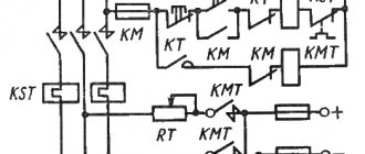
The use of magnetic starters allows you to control asynchronous electric motors by directly connecting the motor to an alternating current network.
Using magnetic starters you can implement the following circuit:
The use of a thermal relay makes it possible to protect the electric motor from current values much higher than the rated value.
Non-reversible circuit
Reversible circuit
The disadvantage of direct commutation of the windings of an asynchronous electric motor with the network is the presence of large starting currents when starting the electric motor.
Smooth start of an asynchronous electric motor
In tasks where it is not necessary to adjust the speed of the electric motor during operation, a soft starter is used to reduce starting currents.
The soft starter protects the asynchronous electric motor from damage caused by a sharp increase in energy consumption during starting by limiting the starting currents. The soft start device allows for smooth acceleration and braking of an asynchronous electric motor.
A soft starter is cheaper and more compact than a frequency converter. Used where adjustment of rotation speed and torque is required only during startup.
Frequency control of an asynchronous electric motor
To regulate the rotation speed and torque of an asynchronous motor, a frequency converter is used. The operating principle of a frequency converter is based on changing the frequency and voltage of alternating current.
Scalar control of an asynchronous motor with a speed sensor
Vector control
used in tasks where it is necessary to independently control the speed and torque of an electric motor (for example, an elevator), which, in particular, makes it possible to maintain a constant rotation speed with a changing load torque. At the same time, vector control is the most effective control in terms of efficiency and increasing the operating time of the electric motor.
Three-phase asynchronous motor with wound rotor
Before the widespread use of frequency converters, medium and high power asynchronous motors were made with a wound rotor. Three-phase slip-rotor induction motors (ASMs) are typically used in applications with severe starting conditions, such as AC crane motors, or to drive devices requiring continuously variable speed control.
ADFR design
Slip rotor
Structurally, the phase rotor is a three-phase winding (similar to the stator winding) placed in the slots of the phase rotor core. The ends of the phases of such a rotor winding are usually connected in a “star”, and the beginnings are connected to slip rings isolated from each other and from the shaft. A three-phase starting or control rheostat is usually connected to the slip rings through brushes. Asynchronous motors with a wound rotor have a more complex design than motors with a squirrel-cage rotor, but have better starting and control properties.
Slip rotor
ADFR stator
The stator of an asynchronous motor with a wound rotor is no different in design from the stator of an asynchronous motor with a squirrel-cage rotor.
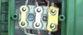
Designation of the terminals of the secondary windings of a three-phase ADDF
| Winding connection diagram, name of phase and output | Pin designation | |
| Start | End | |
| Open circuit (number of pins 6) | ||
| first phase | K1 | K2 |
| second phase | L1 | L2 |
| third phase | M1 | M2 |
| Star connection (number of pins 3 or 4) | ||
| first phase | K | |
| second phase | L | |
| third phase | M | |
| star point (zero point) | Q | |
| Delta connection (number of pins 3) | ||
| first conclusion | K | |
| second conclusion | L | |
| third conclusion | M | |
| Winding connection diagram, name of phase and output | Pin designation | |
| Star connection (number of pins 3 or 4) | ||
| first phase | P1 | |
| second phase | P2 | |
| third phase | P3 | |
| zero point | ||
| Delta connection (number of pins 3) | ||
| first conclusion | P1 | |
| second conclusion | P2 | |
| third conclusion | P3 | |
Start ADFR
Starting of motors with a wound rotor is carried out using a starting rheostat in the rotor circuit.
Wire and liquid rheostats are used.
Metal rheostats
are stepped, and switching from one stage to another is carried out either manually using a controller handle, the essential element of which is a shaft with contacts mounted on it, or automatically using contactors or an electrically driven controller.
Liquid rheostat
is a vessel with electrolyte in which electrodes are lowered. The resistance of the rheostat is adjusted by changing the immersion depth of the electrodes [3].
To increase efficiency and reduce brush wear, some ADFRs contain a special device (short-circuit mechanism), which, after starting, raises the brushes and closes the rings.
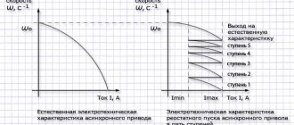
With rheostatic starting, favorable starting characteristics are achieved, since high torque values are achieved at low starting current values. Currently, ADDFs are being replaced by a combination of a squirrel-cage induction motor and a frequency converter.
Source
What is a squirrel cage induction motor
Why does the rotor of an asynchronous motor need a squirrel cage? And does everyone need one? cage motor rotor
Asynchronous brushless motors have two main designs: with a squirrel-cage rotor winding and with a phase-phase rotor winding. The short-circuited rotor winding is otherwise called a “squirrel cage”, because it is externally. resembles a squirrel wheel. The working wires of this winding (rods) are laid uninsulated in the grooves of the rotor, which ensures good use of the groove area and good heat transfer from the rods to the active steel. Asynchronous motors with a wound rotor do not have a “squirrel cage”. Asynchronous motors with a wound rotor usually have semi-closed slots on the rotor, into which a three-phase winding usually fits.
A squirrel-cage motor has no moving contacts. Due to this, such engines are highly reliable. Dolivo-Dobrovolsky was the first to create an engine with a squirrel-cage rotor and study its properties. He found out that such engines have a very serious drawback - limited starting torque. Dolivo-Dobrovolsky named the reason for this shortcoming - a heavily shorted rotor. He also proposed the design of an engine with a wound rotor, which is more efficient.
Because the first phase of starting a synchronous motor is carried out in asynchronous mode. I won't answer in more detail. You have the entire Internet in your pocket. At one time, we sorted through dozens of books (and they are fucking expensive and rare) so that we could now lay everything out for you on a platter. Have a conscience)))))
A squirrel cage is needed by squirrels, and in engines with power up to 100 kW, squirrel cage rods are usually obtained by pouring molten aluminum into the grooves of the rotor core (Fig. 256, c). Together with the rods of the squirrel cage, the end short-circuit rings connecting them are also cast.
not a cage but a wheel, in it an EMF is excited by the alternating magnetic field of the stator, from the EMF in the squirrel-cage rotor its own magnetic field arises, the magnetic fields of the rotor and stator are linked and the engine rotates, the rotor rotates slower than the magnetic field of the stator.
Well. but what about. A friend of mine called himself a carburetor of the 30s, so with his proteins only the cage helped. Even Pushkin wrote about this, remember the Tale of Tsar Saltan: the “squirrel” sings songs and gnaws difficult nuts, but the servants guard the squirrel “(orderlies, that is)
What?)))). Well, if the stator of an asynchronous motor is taken as a “squirrel wheel” (in appearance it still looks more like a wheel than a cage:), then the motor rotor without it, well, it’s absolutely not like a squirrel in it))) But does everyone need it? I think no
A rotating magnetic field is excited in the motor stator; in a short-circuited “squirrel cage” rotor, an oppositely directed field is induced, the rotor rotates, in short. Not everyone has motors with wound rotors.
A rotating magnetic field is excited in the motor stator; in a short-circuited “squirrel cage” rotor, an oppositely directed field is induced, the rotor rotates, in short. Not everyone has motors with wound rotors.
Squirrel cage or squirrel wheel is just an imaginary name. In fact, it is a path without end. That is, a ring along which the magnetic field runs in steps of 60 degrees and carries the rotor along with it.
The short-circuited rotor winding, often called a “squirrel cage” due to the external similarity of the design, consists of copper or aluminum rods short-circuited at the ends with two rings.
Good question, but then why does the stator need a protein in a cage, always late for the moment. Apparently they can’t live without each other. This is the law of movement and drive in our world, full of movement and drive.
Definition and a little history
The author of the asynchronous motor is considered to be Mikhail Osipovich Dolivo-Dobrovolsky, who in 1889 received a patent for a motor with a “Squirrel Cage” type rotor, and in 1890 for a motor with a wound rotor, which are still used today without any special changes in design. And the first research and developments in this direction were carried out in 1888 by Galileo Ferraris and Nikola Tesla independently of each other.
The main difference between Dolivo-Dobrovolsky’s development and Tesla’s development was the use of a three-phase rather than two-phase stator design. The demonstration of the first engines took place at the International Electrotechnical Exhibition in Frankfurt am Main in September 1891. Three three-phase asynchronous electric motors were presented there, the most powerful of which was 1.5 kW. The design of these machines turned out to be so successful that it has not undergone significant changes to this day.
The definition of an asynchronous machine is as follows:
An asynchronous electric machine is an alternating current machine in which the rotor speed is not equal to the speed of the magnetic field created by the stator windings.
Mechanical characteristic of asynchronous motor, slip s
Asynchronous motors are always characterized by slip s, which occurs due to the fact that the synchronous frequency of the rotating magnetic field n1 of the stator is higher than the actual rotor speed n2.
Sliding occurs because the EMF induced in the rods can only occur when the rods move relative to the magnetic field. That is, the rotor is always forced, at least a little, to lag behind the stator’s magnetic field in speed. The amount of slip is s = (n1-n2)/n1.
If the rotor rotated at the synchronous frequency of the stator's magnetic field, then no current would be induced in the rotor bars, and the rotor simply would not rotate. Therefore, the rotor in an asynchronous motor never reaches the synchronous rotation speed of the stator magnetic field, and always lags at least a little behind the synchronous frequency in rotation frequency.
Slip s is measured as a percentage, and at idle it practically approaches 0, when there is almost no counter torque from the rotor. In case of a short circuit (the rotor is locked), the slip is equal to 1.
In general, slip in squirrel-cage asynchronous motors depends on the load and is measured as a percentage. Rated slip is the slip at the rated mechanical load on the shaft under conditions where the supply voltage corresponds to the motor rating.
Three-phase squirrel-cage asynchronous motor
, in which the rotor is made with a short-circuited winding in the form of a squirrel cage
Construction of an asynchronous electric motor
A three-phase asynchronous electric motor, like any electric motor, consists of two main parts - a stator and a rotor. The stator is the stationary part, the rotor is the rotating part. The rotor is placed inside the stator. There is a small distance between the rotor and stator, called an air gap, usually 0.5-2 mm.
Stator
consists of a body and a core with a winding. The stator core is assembled from thin sheet technical steel, usually 0.5 mm thick, coated with insulating varnish. The laminated core design contributes to a significant reduction in eddy currents arising during the process of magnetization reversal of the core by a rotating magnetic field. The stator windings are located in the slots of the core.
Rotor
consists of a core with a short-circuited winding and a shaft. The rotor core also has a laminated design. In this case, the rotor sheets are not varnished, since the current has a low frequency and the oxide film is sufficient to limit eddy currents.
Principle of operation. Rotating magnetic field
The operating principle of a three-phase asynchronous electric motor is based on the ability of a three-phase winding to create a rotating magnetic field when connected to a three-phase current network.
A rotating magnetic field is the basic concept of electric motors and generators.
Rotating magnetic field of an asynchronous electric motor
The rotation frequency of this field, or the synchronous rotation frequency, is directly proportional to the frequency of the alternating current f1 and inversely proportional to the number of pole pairs p of the three-phase winding.
,
Rotating magnetic field concept
To understand the rotating magnetic field phenomenon better, consider a simplified three-phase winding with three turns. Current flowing through a conductor creates a magnetic field around it. The figure below shows the field created by three-phase alternating current at a specific point in time
Repair of squirrel-cage rotors
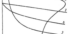
In squirrel-cage rotors of asynchronous electric motors, damage to the squirrel cage is most often observed, which is expressed in the weakening of the rods in the groove, loss of contact at the points where the rod is soldered to the short-circuiting rings, the formation of cracks and breaks of the rods. Loosening the fastening of the rod in the groove leads to an increase in its vibration, which causes alternating deformations, as a result of which cracks form at the point where the rod exits the groove and at the connection points with the short-circuit rings. These cracks can lead to the rod breaking, and the torn ends of the rod, bending under the action of centrifugal forces, can damage the insulation of the frontal parts. Such damage is typical for electric motors that have a large number of starts. Some types of electric motors experience an increase in vibration due to loosening or breakage of the spacer wedges of the rotor winding rods. These defects are identified when disassembling the electric motor. When the electric motor is running, the following signs indicate the presence of broken rods in the squirrel cage.