Single-phase 220V motor - problem statement
Let's assume that an asynchronous single-phase motor, already connected using a starting-charging capacity, initially has a shaft rotation directed clockwise, as in the picture below (single-phase motor 220V)
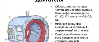
Single-phase motor connection diagram
Let's clarify the important points:
- Point A marks the beginning of the starting winding, and point B marks its end. A brown wire is connected to the starting terminal A, and a green wire is connected to the ending terminal.
- Point C marks the beginning of the working winding, and point D marks its end. A red wire is connected to the initial contact, and a blue wire is connected to the final contact.
- The direction of rotation of the rotor is indicated by arrows.
We set ourselves the task of reversing a single-phase motor without opening its housing so that the rotor begins to rotate in the other direction (in this example, against the movement of the clock hand). It can be solved in three ways. Let's take a closer look at them.
Option 1: reconnection of the working winding (single-phase motor 220V)
To change the direction of rotation of the motor, you can only swap the beginning and end of the working (permanently on) winding, as shown in the figure. You might think that to do this you would have to open the case, take out the winding and turn it over. There is no need to do this, because it is enough to work with the contacts from the outside:
- There should be four wires coming out of the housing. 2 of them correspond to the beginnings of the working and starting windings, and 2 to their ends. Determine which pair belongs only to the working winding.
- You will see that two lines are connected to this pair: phase and zero. With the motor turned off, reverse the phase by changing the phase from the initial winding contact to the final one, and zero - from the final to the initial one. Or vice versa.
Connection diagram for a single-phase motor
As a result, we get a diagram where points C and D change places. Now the rotor of the asynchronous motor will rotate in the other direction.
Why is engine reverse needed?
Many mechanical actions in household and industrial devices are carried out using an asynchronous engine. In connection with this, there is often a need to change the direction of movement, based on the tasks being performed. Sometimes the reverse function for a mechanism is permanent, and sometimes it is temporary.
- The first type includes all lifting mechanisms, cranes, electric drives of shut-off and control devices and actuators operating in the “open/close” mode.
- Another type of reverse includes mechanisms in which this function is used very rarely, usually in emergency situations: conveyors, escalators, pumping units.
The reverse function in an electric motor is sometimes used for braking, since when it is disconnected from the electrical network, the rotor, having significant inertia, continues to operate. Such a short-term start of reverse causes the engine to slow down. This method is also called counter-inclusion.
Subscribe to the newsletter
In order for mechanisms in production or at home, be it wood or metalworking machines, a cantilever pump, a conveyor belt, a crane beam, a sharpening machine, an electric lawn mower, a feed chopper or another device to work without breakdowns, it is necessary, first of all, for the electric motor shaft to rotate in the right direction.
In order to avoid mistakes and prevent rotation of the mechanism shaft in the opposite direction, in accordance with paragraph 2.5.3 of the “Rules for the technical operation of consumer electrical installations,” arrows in the direction of rotation of the electric motor .
Motor shaft rotation direction
The direction of rotation of the electric motor is determined from the single end of the shaft. If the engine has two shaft ends, then rotation is determined from the side of the shaft, which has a larger diameter. According to GOST 26772-85, the right direction corresponds to clockwise shaft movement. For the most common three-phase motors with a squirrel-cage rotor, the shaft will rotate to the right if the sequence of phases through which voltage is supplied to the ends of the stator windings corresponds to the alphabetical sequence of their markings - U1, V1, W1.
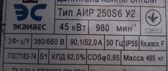
Model overview
One of the most popular are electric motors of the AIR series. There are models made on feet 1081, and models of combined design - feet + flange 2081.
Electric motors in the foot + flange design will cost about 5% more than similar ones with feet.
As a rule, manufacturers provide a warranty of 12 months.
Read also: What types of manual metal scissors are there?
For electric motors with a rotation height of 56-80 mm, the frame is made of aluminum. Motors with a rotation height of more than 90 mm are available in cast iron.
Models differ in power, rotation speed, height of the rotation axis, and efficiency.
The more powerful the engine, the higher its cost:
- An engine with a power of 0.18 kW can be purchased for 3 thousand rubles (electric motor AIRE 56 B2).
- A model with a power of 3 kW will cost about 10 thousand rubles (AIRE 90 LB2).
The height of the rotation axis for motors with 1 phase varies from 56 mm to 90 mm and directly depends on the power: the more powerful the engine, the greater the height of the rotation axis, and therefore the price.
Different models have different efficiencies, typically ranging from 67% to 75%. Greater efficiency corresponds to a higher cost of the model.
You should also pay attention to engines produced by the Italian company AACO, founded in 1982:
- Thus, the AACO series 53 electric motor is designed specifically for use in gas burners. These motors can also be used in washing installations, warm air generators, and central heating systems.
- Electric motors of the 60, 63, 71 series are designed for use in water supply installations. Also, the company offers universal motors of the 110 and 110 compact series, which are distinguished by a diverse range of applications: burners, fans, pumps, lifting devices and other equipment.
You can buy motors produced by AACO for a price starting from 4,600 rubles.
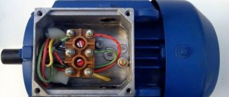
Single-phase asynchronous electric motors
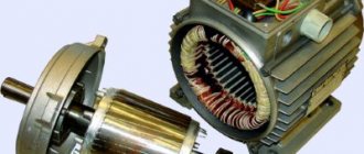
Device and principle of operation
The power of such a single-phase 220V motor can, depending on the design, range from 5 W to 10 kW. Its rotor is usually a short-circuited winding (“squirrel cage”) - copper or aluminum rods closed at the ends.
Such a single-phase motor usually has two windings offset by 90° relative to each other. The working (main) one occupies most of the stator slots, and the starting (auxiliary) one occupies the remaining part. And it is called single-phase because it has only one working winding.
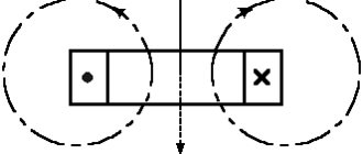
Alternating current flowing through the main winding creates a periodically changing magnetic field. It can be considered to consist of two circular ones with the same amplitude, rotating towards each other.
According to the law of electromagnetic induction, in closed turns of the rotor, a changing magnetic flux creates an induced current that interacts with the field that generates it. If the rotor is stationary, the moments of the forces acting on it are the same, as a result of which the rotor remains stationary.
If the rotor begins to rotate, then the equality of the moments of these forces will be violated, since the sliding of its turns relative to the rotating magnetic fields will become different. As a consequence, the Ampere force acting on the rotor turns from the direct magnetic field will be significantly greater than from the reverse one.
An induced current in the rotor turns can only arise when they cross the magnetic field lines. And to do this, they must rotate at a speed slightly lower than the field rotation frequency (with one pair of poles - 3000 rpm). Hence the name that such electric motors received, asynchronous.
Basic faults
The sparking that occurs between the brushes and the commutator is the most important issue that requires attention. To avoid more serious malfunctions, such as peeling and deformation of the lamellas or overheating of the lamellas, a worn-out brush must be replaced.
In addition, a short circuit between the armature and stator windings is possible, causing strong sparking at the commutator-brush junction or a significant drop in the magnetic field.
To extend the service life of the engine, two conditions must be met - a professional manufacturer and a competent user, i.e. strict adherence to operating hours.
Video: Brushed electric motor
We are returning again to the world of entertaining things - like electrical engineering , because I think that we all simply need this knowledge in our daily lives.
Read also: Why the soldering iron does not heat up
Reverse movement principle
To change the direction of rotation of an AC motor, you need to change the magnetic fields that cause movement in the opposite direction. Since in magnetic fields each wire is connected to a positive and negative current, replacing the main and starting wires will cause the motor to rotate in the opposite direction. This simple method of switching wires works by reversing the polarity of the magnetic field.
Option 2: reconnecting the starting winding
The second way to organize the reverse of a 220 Volt asynchronous motor is to swap the beginning and end of the starting winding. This is done by analogy with the first option:
- Of the four wires coming out of the motor box, find out which of them correspond to the starter winding taps.
- Initially, end B of the starting winding was connected to the beginning C of the working winding, and beginning A was connected to the starting-charging capacitor. You can reverse a single-phase motor by connecting the capacitance to terminal B, and the beginning of C to the beginning of A.
Topic: DSR-10/120 engine from MEO gearbox
Quick link Technical office Up
- Navigation
- Cabinet
- Private messages
- Subscriptions
- Who's on the site
- Search the forum
- Forum home page
- Forum
- TECHNICAL FORUMS ON CQHAM.RU
- Transceivers, HF/VHF receivers Kenwood TS-50
- TS-140
- TS-430
- TS-440
- TS-450
- TS-480
- TS-520
- TS-570
- TS-590
- TS-680
- TS-690
- TS-790
- TS-830
- TS-850
- TS-870
- TS-930
- TS-940
- TS-950
- TS-990
- TS-2000
- Icom
- IC-746 (IC-7400)
- IC-756
- IC-706
- IC-775, IC-775DSP, IC-775DX2
- IC-7600
- IC-7800
- IC-7700
- IC-910
- IC-703
- IC-7000
- IC-780, 781
- IC-7200
- IC-718 (IC-78)
- IC-760 (IC-761)
- Yaesu
- FT-100
- FT-101
- FT-450
- FT-757
- FT-767
- FT-817
- FT-840
- FT-847
- FT-857
- FT-890
- FT-897
- FT-900
- FT-920
- FT-950
- FT-990
- FT-1000
- FT-2000
- FT-DX3000
- FT-DX5000
- FT-DX9000
- Ten-Tec
- Elecraft
- Alinco
- UW3DI
- UA1FA
- RA3AO
- S.W.
- Power amplifiers
- HF amplifiers
- VHF amplifiers
- Antennas
- HF Antennas
- VHF Antennas
- Matching devices
- Antenna devices
- Antenna mechanics
- Direct conversion technique
- Technical office
- Measurements
- Technologies
- Interference
- Untested ideas
- Modification of radio stations
- Microcontroller designs for radio amateurs
- Old Radio (Tube Souls)
- History of radio communications
- Household appliances, my car
- Office equipment
- TV
- Auto-Moto
- Power supplies
- AMATEUR RADIO FORUMS
- For HF fans DX news
- Expeditions
- Competitions
- Diplomas
- Walkthrough
- For VHF lovers
- VHF equipment
- VHF antennas
- VHF competitions, diplomas
- Programs for VHF
- Tropo, Aurora and Es
- EME communications
- MS communications
- SAT communications
- For fans of QRP and QRPP
- Hiking
- Software
- Software for mobile devices
- Groups and Radio
- Silent Keys
- Legal workshop for radio amateur
- For beginners
- NEW IN AMATEUR RADIO COMMUNICATIONS
- Digital communications New technologies in electronics and communications
- Software Defined Radio (SDR), Digital Radio Mondiale (DRM)
- APRS and other types of packet communications News and events
- Application of APRS on HF and VHF
- APRS equipment
- Homemade APRS equipment
- Software
- Various Applications of APRS
- Digital communications for data transmission
- Amateur radio cards
- CQHAM.RU USER SUPPORT
- About the forums on CQHAM.RU
- Test forum
- OFF-TOPIC
- Topics not included in other sections of the forum
- Work for a radio amateur
- Sellers, buyers...
- I am looking for you
- QRZ.RU
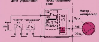
Reversing diagram of a three-phase motor in a single-phase network
Since a three-phase asynchronous motor will lack two phases, they need to be compensated with capacitors - starting and running, to which both windings are switched. The torsion of the shaft in one direction or another depends on where to attach the third.
The diagram below shows that winding number 3 is connected through a working capacitor to a three-position toggle switch, which is responsible for the forward/reverse engine operating modes. Its other two contacts are combined with windings 2 and 1.
When turning on the engine, you must adhere to the following algorithm of actions:
- Apply power to the circuit through a plug or switch.
- Move the toggle switch to switch operating modes to forward or reverse (reverse).
- Set the power switch to the ON position.
- Press the “Start” button for a time not exceeding three seconds to start the engine.
Reversing three-phase asynchronous machines
The direction of movement of the rotating magnetic field of asynchronous electric motors depends on the order of the phases, regardless of whether its stator windings are connected by a star or a triangle. For example, if phases A, B, C are applied to input terminals 1, 2 and 3, respectively, then the rotation will go (supposedly) clockwise, and if to terminals 2, 1, and 3, then counterclockwise. The connection diagram via a magnetic starter will save you from the need to unscrew the nuts in the terminal box and physically rearrange the wires.
Three-phase asynchronous machines at 380 volts are usually connected with a magnetic starter, in which three contacts are located on the same frame and close simultaneously, subject to the action of the so-called retractor coil - a magnetic solenoid operating on both 380 and 220 volts. This saves the operator from close contact with live parts, which can be unsafe at currents above 20 amperes.
For reverse starting, a pair of starters is used. The supply voltage terminals at the input are connected in a direct manner: 1–1, 2–2, 3–3. And at the exit counter: 4–5, 5–4, 6–6. To avoid a short circuit when accidentally pressing two “Start” buttons on the control panel simultaneously, voltage is supplied to the retractor coils through additional contacts of opposite starters. So that when the main group of contacts is closed, the line that goes to the solenoid of the adjacent device is open.
The control panel is equipped with a three-button post with single-position – one action per press – buttons: one “Stop” and two “Start”. The wiring in it is as follows:
- one phase wire is fed to the “Stop” button (it is always normally closed) and jumpers from it to the “Start” buttons, which are always normally open.
- From the “Stop” button there are two wires to additional contacts of the starters, which close when they are triggered. This ensures blocking.
- From the “Start” buttons, cross one wire to the additional contacts of the starters, which open when they are triggered.
Read more about connection diagrams for magnetic starters for three-phase electric motors here.
Normative references
This standard uses normative references to the following standard:
GOST 23851-79 Gas turbine aviation engines. Terms and Definitions
Note - When using this standard, it is advisable to check the validity of the reference standards in the public information system - on the official website of the national body of the Russian Federation for standardization on the Internet or according to the annually published information index “National Standards”, published as of January 1 of the current year, and according to the corresponding monthly information indexes published in the current year. If the reference document is replaced (changed), then when using this standard you should be guided by the replacing (changed) document. If the reference document is canceled without replacement, then the provision in which a reference to it is given applies to the part that does not affect this reference.
Connection features
As mentioned above, not every frequency converter can work with a single-phase motor, since when it is connected, the third (unconnected) phase will actually be open, which will cause an error. Therefore, it is necessary to carefully read the documentation for the inverter - the manufacturer must clearly indicate that it is possible to connect and operate a single-phase load.
Since a single-phase motor contains a capacitor, when changing the operating frequency it will not be possible to provide the required phase shift, and the motor will overheat at lower frequencies (less than 30 Hz). This should be taken into account when choosing the operating frequency range and the drive cooling method.
When a single-phase motor is connected, operational reverse via the control panel or inverter settings is not possible. You can change the direction of rotation by changing the wiring diagram of the windings inside the motor.
Option 3: changing the starting winding to the working winding, and vice versa
It is possible to organize the reverse of a single-phase 220V motor using the methods described above only if taps from both windings with all beginnings and ends come out of the housing: A, B, C and D. But there are often motors in which the manufacturer intentionally left them outside only 3 contacts. In this way, he protected the device from various “homemade products”. But still there is a way out.
Changing the starting winding to the working winding, and vice versa
The figure above shows a diagram of such a “problematic” motor. It only has three wires coming out of the housing. They are marked with brown, blue and purple colors. The green and red lines corresponding to the end B of the starting winding and the beginning C of the working winding are interconnected internally. We will not be able to access them without disassembling the engine. Therefore, it is not possible to change the rotor rotation using one of the first two options.
In this case, do this:
- Remove the capacitor from the initial terminal A;
- Connect it to the final terminal D;
- From wires A and D, as well as the phase, taps are made (you can reverse it using a key).
Single-phase motor connection diagram
Look at the picture above. Now, if you connect the phase to tap D, the rotor rotates in one direction. If the phase wire is transferred to branch A, then the direction of rotation can be changed in the opposite direction. Reversing can be done by manually disconnecting and connecting the wires. Using a key will help make the job easier.