Subscribe to the newsletter
Modern electric motors are reliable power units. They can work for decades with timely maintenance and repair. To do this, it is necessary to regularly lubricate the bearings, replace them on time, and also monitor the condition of the stator windings.
Why check the insulation resistance of an electric motor?
Even if the equipment has not been operating for some time, it is necessary to measure the insulation resistance, since it is hygroscopic and can change its properties under the influence of air humidity. The reduction in resistance can be quite significant, so before connecting the machine to the network, the insulation resistance of the electric motor must be checked. According to the requirements of the rules for technical operation of consumer electrical installations (PTEEP), such a procedure is carried out before putting the electric motor into operation, after routine and major repairs, as well as during scheduled tests once every three years. Insulation resistance is measured after routine and scheduled repairs to control the quality of its implementation.
What devices are needed
The resistance of each winding relative to the housing is checked, as well as the resistance between the windings. To change the insulation resistance of the stator windings of an electric motor relative to the housing, a megohmmeter is used, a convenient and compact device consisting of an ohmmeter and a magnetoelectric DC generator. To check the resistance between the windings, use a multimeter in ohmmeter mode. The resistance between the windings must be the same. The insulation resistance of an electric motor with a rated voltage of up to 660V should be measured at a voltage of 500V. If the resistance of the windings of a machine with a rated voltage of up to 3000 V is monitored, then megohmmeters with a voltage of 1000 V are used. To measure the winding resistance of an electric motor with a rated voltage of more than 3000V, instruments with a value of 2500V are used. If the motor under test has a phase-shifting capacitor, then it must be disconnected from the winding before measurement.
How to correctly measure insulation resistance
Measurements must be made at an air temperature not lower than +5°C. Before research you must:
• de-energize the electric motor; • remove residual charges from it by grounding the windings for 2-3 minutes.
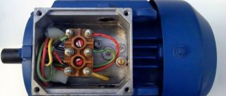
The measuring wire with a clamp from the “L” (or “MΩ”) socket is connected to one of the winding terminals, and the wire from the “Z” (or “–”) socket is connected to the grounding screw in the terminal box or to the motor housing. To carry out the measurement, you need to rotate the generator handle at a speed of about 120 rpm. Measurement data is recorded after the needle has settled in place after 15 and after 60 seconds. Only if these conditions are met can the obtained result be considered reliable. After the measurement has been made, the engine being tested must be discharged. When carrying out tests, the temperature at which the resistance of the electric motor windings was measured must be taken into account. The results obtained must comply with the standards specified in PTEEP Appendix 3, paragraph 23, as well as Table No. 28 of Appendix 3.1 (for motors with voltages over 1 kV). At an insulation temperature equal to the ambient temperature, the motor winding resistance must be at least 1 MOhm. The resistance of the motor winding of a DC machine is at least 0.5 MOhm.
Source: cable.ru
Types of electric motors
The most common electric motors are;
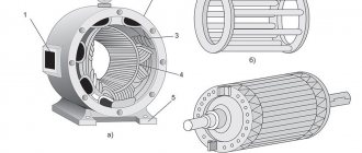
Three-phase asynchronous squirrel-cage motor
— asynchronous three-phase motor with a squirrel-cage rotor. Three motor windings are laid in the stator slots; — asynchronous single-phase motor with a squirrel-cage rotor. It is mainly used in household electrical appliances in vacuum cleaners, washing machines, hoods, fans, air conditioners; — brushed DC motors are installed in the electrical equipment of the car (fans, window regulators, pumps); - AC commutator motor is used in electrical tools. Such tools include electric drills, grinders, hammer drills, meat grinders; — an asynchronous motor with a wound rotor has a fairly powerful starting torque. Therefore, such motors are installed in lift drives, cranes, and elevators.
Winding insulation resistance measurement
To test a motor for insulation resistance, electricians use a megger with a test voltage of 500 V or 1000 V. This device measures the insulation resistance of motor windings designed for an operating voltage of 220 V or 380 V.
For electric motors with a rated voltage of 12V, 24V, a tester is used, since the insulation of these windings is not designed for testing under the high voltage of 500 V megger. Typically, the motor data sheet indicates the test voltage when measuring the insulation resistance of the coils.
Insulation resistance is usually checked with a megger
Before measuring the insulation resistance, you need to familiarize yourself with the connection diagram of the electric motor, since some star connections of the windings are connected at a midpoint to the motor housing. If the winding has one or more connection points, delta, star, single-phase motor with starting and running windings, then the insulation is checked between any connection point of the windings and the housing.
If the insulation resistance is significantly less than 20 MΩ, the windings are disconnected and each is checked separately. For a complete motor, the insulation resistance between the coils and the metal casing must be at least 20 MΩ. If the motor has been operated or stored in damp conditions, then the insulation resistance may be below 20 MΩ.
Then the electric motor is disassembled and dried for several hours with a 60 W incandescent lamp placed in the stator housing. When measuring insulation resistance with a multimeter, set the measurement limit to the maximum resistance, megohms.
Measurement - Ohmic Resistance - Winding
The ohmic resistance of the windings is measured using the resistance method (voltmeter and ammeter), which, when using devices of class 0 2 or 0 5, ensures high accuracy. A voltmeter that measures the voltage drop is connected directly to the terminals of the winding being measured. The voltmeter is connected to the armature winding with special probes installed on the commutator plates located between the brushes. Ohmic resistance is measured before testing the machines (in a practically cold state); the resulting value is recalculated to a temperature of 20 C. The resistance should not differ from the nominal (certificate) value by 10% for repaired machines. [1]
The ohmic resistance of the windings is measured using a bridge, as described in Chapter X. [2]
How to test an electric motor for broken windings and interturn short circuits
Turn-to-turn short circuits in the windings can be checked with an ohm multimeter. If there are three windings, then it is enough to compare their resistance. The difference in the resistance of one winding indicates an interturn short circuit. The interturn short circuit of single-phase motors is more difficult to determine, since there are only different windings - this is the starting and operating winding, which has less resistance.
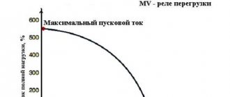
There is no way to compare them. You can detect the interturn short circuit of the windings of three-phase and single-phase motors using clamp meters, comparing the winding currents with their passport data. When there is an interturn short circuit in the windings, their rated current increases, and the starting torque decreases, the engine starts with difficulty or does not start at all, but only hums.
FAQ on electric motors
1. What electric motors are used most often?
The most common are asynchronous electric motors with a squirrel-cage rotor. They have a relatively simple design and are relatively inexpensive.
To operate an asynchronous motor, a three-phase voltage is required, which creates a rotating magnetic field on the stator windings. This field drives the motor rotor, which transmits torque to a load, such as a fan propeller or conveyor gearbox. By changing the configuration of the stator windings, you can change the main characteristics of the drive - speed and shaft power. When an asynchronous electric motor operates in a single-phase network, phase-shifting and starting capacitors are used.
DC motors are also currently being used
. These drives have brushes that are subject to wear and sparking. In addition, a bias (excitation) winding is required, to which a constant voltage is applied. Despite these disadvantages, DC motors are used where rapid speed changes and torque control are required, as well as for powers above 100 kW.
In everyday life, commutator (brush) AC motors are also used, which have low reliability compared to asynchronous ones.
2. What methods of controlling electric motors are used in practice?
Controlling an electric motor implies the ability to change its speed and power. So, if a voltage of a given magnitude and frequency is applied to an asynchronous motor, it will rotate at the rated speed and will be able to provide power on the shaft no more than the nominal value. If you need to lower or increase the speed of the electric motor, frequency converters are used. The inverter can provide the required acceleration and deceleration modes, and will also allow you to quickly control the operating frequency.
To ensure the required acceleration and deceleration without changing the operating frequency, a soft start device (SPD) is used. If you only need to control engine acceleration, use a star-delta connection circuit.
To start motors without inverters and soft starters, contactors are widely used, which allow remote control of start, stop and reverse.
3. How to ring an electric motor and determine its resistance?
An asynchronous electric motor usually has three windings. Each winding has two terminals, which must be marked in the motor terminal box. If the terminals of the windings are known, then you can easily ring each of them and compare the resistance value with the other windings. If the resistance values differ by no more than 1%, then most likely the windings are working.
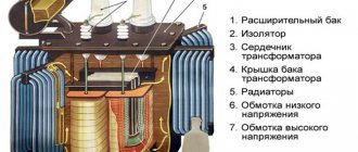
The resistance of the motor windings is measured using an ohmmeter, just like the resistance of the transformer windings. The greater the engine power, the lower the resistance of its windings, and vice versa.
4. How to determine the power of an electric motor?
The easiest way to determine the rated power of an electric motor is by looking at the nameplate. It indicates the mechanical power (shaft power), the value of which is always less than the power consumption due to losses due to friction and heating. However, if there is no nameplate on the motor housing, you can very roughly estimate the characteristics of the drive based on its dimensions. With the same power, an engine with a larger shaft diameter will have higher shaft power and a lower speed.
Also, power can be determined by the load and by the settings of the protective devices through which the engine is powered (automatic motor, thermal relay).
Another way is to turn on the engine at rated power, ensuring the required load on the shaft. After this, we measure the current with a current clamp, which should be the same in all windings. To roughly estimate the power of an asynchronous motor connected in a star configuration, you need to divide the rated measured current by 2.
5. How to increase or decrease the speed of the electric motor?
Controlling the engine rotation speed is necessary in three operating modes - during acceleration, braking, and in operating mode.
The most universal way to control speed is to use a frequency converter. By adjusting the inverter settings, you can achieve any rotation speed within the technical limits. At the same time, you can control other parameters of the electric motor, as well as monitor its condition during operation. The frequency can be changed either smoothly or stepwise.
Controlling engine speed in acceleration and deceleration modes is possible using a soft starter. This device allows you to significantly reduce the starting current due to smooth acceleration with a slow increase in speed.
How to check the motor winding on the stator: general recommendations
The three-phase stator has three built-in windings. There are six wires coming out of it. In some designs you can find 3 or 4 terminals, when the triangle or star connection is assembled inside the housing. But this is rarely done.
Testing them with a multimeter in ohmmeter mode allows you to determine whether the ends are connected to the windings. You just need to place one probe on an arbitrary pin, and use the other one to alternately measure the active resistance on all the others.
The pair of wires on which resistance in Ohms is detected will belong to the same winding. They should be visually separated and marked, for example, with the number 1. Do the same with other wires.
Here we must clearly understand that, according to Ohm’s law, the current in the winding is created under the influence of the applied voltage, which is counteracted by the total resistance, and not by the active one measured by us.
We take into account that the windings are wound from the same wire with the same number of turns, creating equal inductive reactance. If the wire is short-circuited or torn during operation, its active component, as well as its full value, will be disrupted.
The interturn short circuit also affects the value of the active component.
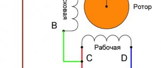
Single-phase asynchronous motor: features of stator windings
Such models are created with two windings: working and starting, like, for example, a washing machine. In the vast majority of cases, the active resistance of the working chain is always less.
Therefore, when only three ends are removed from the stator, this means that the resistance must be measured between all of them. The results of three measurements will show:
How to find the beginning and end of each winding
The method only allows you to identify the general winding direction of each wire. But for practical operation of the electric motor this is more than enough.
The stator is considered as an ordinary transformer, which in principle is what it actually is: the same processes occur in it.
To operate, you will need a small constant voltage source (a regular battery) and a sensitive voltmeter. Better than a pointer. It displays information more clearly. It is difficult to monitor the change in sign of a rapidly changing pulse on a digital multimeter.
A voltmeter is connected to one winding, and voltage from the battery is briefly applied to the other winding and immediately removed. The deviation of the arrow is assessed.
If, when applying a “plus” to the first winding, an electromagnetic pulse was transformed into the second, deflecting the arrow to the right, and when it is turned off, it moves to the left, then it is concluded that the wires have the same direction when the “+” of the device and the source coincide.
Otherwise, you need to switch the voltmeter or battery - that is, change the ends of one of the windings. The next third chain is checked in the same way.
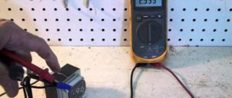
And then I simply took my working asynchronous engine with a multimeter and showed with photographs the method for evaluating it.
Personal experience: checking the stator windings of an asynchronous electric motor
For this article I used my new Mestek MT102 pocket multimeter. At the same time, I continue to identify the shortcomings of its design, which I already showed in the article earlier.
Electrical tests were carried out on a three-phase motor connected to a single-phase network through capacitors in a star configuration.
General assessment of the winding insulation condition
Since all the windings are already assembled together at the terminal terminals, I started taking measurements by checking their insulation resistance relative to the housing. One probe is located on the terminal block of the zero assembly, and the second is on the socket of the cover fastening screw. My Mestek showed no leaks.
I didn't expect any other result. This method of measuring the insulation condition is very inaccurate and it simply cannot detect most damage: 3 volt battery power is clearly not enough.
But it’s still better to do at least this way than to completely neglect such a check.
To fully analyze the dielectric layer of conductors, it is necessary to use the high voltage that megohmmeters produce. Its value usually starts from 500 volts and above. The home master does not have such devices.
You can do it indirectly, using a household network. To do this, a voltage of 220 volts is supplied to the winding and housing terminals through an incandescent test lamp with a power of about 75 watts (a current-limiting resistance that excludes the supply of phase potential to the circuit) and a series-connected ammeter.
The expected leakage current through normal insulation will not exceed microamps or their fractions, but you need to count on emergency mode and start measuring within amperes. By measuring the current and voltage, the insulation resistance is calculated.
When using this method, keep in mind that:
Measurement of winding resistance
Here you need to disassemble the wiring diagram and remove all jumpers. I switch the multimeter to ohmmeter mode and determine the active resistance of each winding.
This is one of the disadvantages of this multimeter. The probe does not fit well into the crocodile groove, and besides, the thin metal of the clamp moves apart. I immediately had to tighten it with pliers.
1.8.15. AC motors
| Home // Our library // Norms, rules, standards // Rules for the construction of electrical installations (PUE) // PUE. Chapter 1.8. Seventh edition // 1.8.15. AC motors | 1.8.15. AC motors AC electric motors with voltage up to 1 kV are tested according to paragraphs. 2, 4b, 5, 6. AC electric motors with voltages above 1 kV are tested according to paragraphs. 1-6. 1. Determining the possibility of switching on electric motors with voltages above 1 kV without drying. AC electric motors are switched on without drying if the insulation resistance and absorption coefficient are not lower than those indicated in the table. 1.8.9. Acceptable values of insulation resistance and absorption coefficient for stator windings of electric motors | Not less than 1.3 at a temperature of 10-30 °C |
| 2. Power 5 MW and below, voltage above 1 kV, thermosetting insulation | ||
| 3. Motors with mica compound insulation, voltage above 1 kV, power from 1 to 5 MW inclusive, as well as motors of lower power for outdoor installation with the same insulation with voltage above 1 kV | Not lower than the values specified in table 1.8.10. | Not less than 1.2 |
| 4. Motors with mica compound insulation, voltage above 1 kV, power more than 1 MW, except for those specified in clause 3 | Not lower than the values specified in table 1.8.10. | – |
| 5. Voltage below 1 kV, all types of insulation | Not lower than 1.0 MΩ at a temperature of 10-30 °C | – |
| 6. Rotor winding | 0,2 | – |
| 7. Thermal indicators with connecting wires, bearings | In accordance with manufacturers' instructions | |
2. Insulation resistance measurement.
Permissible values of insulation resistance of electric motors with voltages above 1 kV must comply with the standards given in Table 1.8.10.
The lowest permissible values of insulation resistance for electric motors (Table 1.8.9, paragraphs 3, 4)
| Winding temperature, °C | Insulation resistance R60″, MOhm, at rated winding voltage, kV | ||
| 3-3,15 | 6-6,3 | 10-10,5 | |
| 10 | 30 | 60 | 100 |
| 20 | 20 | 40 | 70 |
| 30 | 15 | 30 | 50 |
| 40 | 10 | 20 | 35 |
| 50 | 7 | 15 | 25 |
| 60 | 5 | 10 | 17 |
| 75 | 3 | 6 | 10 |
For synchronous electric motors and electric motors with a wound rotor for a voltage of 3 kV and higher or a power of more than 1 MW, the rotor insulation resistance is measured with a megohmmeter for a voltage of 1000 V. The measured resistance value must be at least 0.2 MOhm.
3. Power frequency high voltage test.
Produced on a fully assembled electric motor. The stator winding is tested for each phase separately relative to the housing with the other two connected to the housing. For motors that do not have terminals for each phase separately, it is allowed to test the entire winding relative to the housing. The test voltage values are given in Table 1.8.11. The duration of test voltage application is 1 min.
Power frequency test voltages for AC motor windings
| Test element | Electric motor power, kW | Rated voltage of the electric motor, kV | Test voltage, kV |
| 1. Stator winding | Less than 1.0 From 1.0 and up to 1000 From 1000 and more From 1000 and more From 1000 and more | Below 0.1 Below 0.1 Above 0.1 Up to 3.3 inclusive Over 3.3 up to 6.6 inclusive Over 6.6 | 0.8 (2Unom. + 0.5) 0.8 (2Unom. + 1) 0.8 (2Unom. + 1), but not less than 1.2 0.8 (2Unom. + 1) 0.8 (2Unom. + 3) |
| 2. Rotor winding of synchronous electric motors intended for direct starting, with an excitation winding closed to a resistor or power source. | 8 times Unom. excitation systems, but not less than 1.2 and not more than 2.8 | ||
| 3. Rotor winding of an electric motor with a wound rotor. | – | – | 1.5 Up*, but not less than 1.0 |
| 4. Resistor of the field damping circuit of synchronous motors. | – | – | 2,0 |
| 5. Rheostats and ballast resistors. | – | – | 1.5 Up*, but not less than 1.0 |
_____________ * voltage on the rings with the stationary rotor open and the rated voltage on the stator.
4. DC resistance measurement.
The measurement is taken when the machine is practically cold.
a) Stator and rotor windings*
______________ * The DC resistance of the rotor winding is measured for synchronous electric motors and asynchronous electric motors with a wound rotor.
The measurement is carried out for electric motors with voltages of 3 kV and higher. Reduced to the same temperature, the measured values of the resistance of the various phases of the windings, as well as the field windings of synchronous motors, should not differ from each other and from the original data by more than 2%.
b) Rheostats and starting resistors For rheostats and starting resistors installed on electric motors with voltages of 3 kV and above, the resistance is measured on all branches. For electric motors with voltages below 3 kV, the total resistance of the rheostats and starting resistors is measured and the integrity of the taps is checked. Resistance values should not differ from the original values by more than 10%.
5. Checking the operation of the electric motor at idle or with the mechanism unloaded.
The duration of the test is at least 1 hour.
6. Checking the operation of the electric motor under load.
Produced at the load provided by the process equipment at the time of commissioning. In this case, for an electric motor with adjustable rotation speed, control limits are determined. The thermal and vibration condition of the engine is checked.
Source: www.sonel.ru
Measuring the resistance of DC windings in a cold state
The measurement is carried out in a practically cold state, in which the temperature of any part of the electrical machine differs from the ambient temperature by no more than . The accuracy of determining a number of important quantities depends on the accuracy of measuring the resistance of windings in a cold state. During industrial testing of electrical machines, only those resistance measurement methods that satisfy the following requirements can be used:
Sufficient measurement accuracy. The method must provide an error in measuring the winding resistance that does not exceed that with which its temperature is measured in a practically cold state. For tests that have less stringent requirements, the resistance measurement error can be allowed up to 1%.
Fast measurements. In some cases, the moment of measurement must be clearly oriented in time, which is impossible if the measurement requires painstaking operations.
Measurements in accordance with GOST 11828-86 and GOST 3484-88 are recommended to be carried out:
—voltmeter and ammeter method;
—single (Winston) or double (Thomson) bridge method;
—by the ohmmeter method of the ratiometric system.
To measure the resistance of transformer windings, the first two methods are used.
The voltmeter and ammeter method best suits all requirements; provided that instruments of the appropriate class are used, it provides the required accuracy, provides greater speed of measurements and easily adapts to the requirements of the mobility of the measuring device. For the method to give sufficiently correct results, a number of conditions must be met:
1. The voltmeter must be connected directly to the terminals of the measured object; if needles are used for connection, they must be well sharpened and made of hardened steel in order to pierce the oxide film on the surface of the metals.
2. The number of detachable contacts in the circuit should be minimal, and all permanent ones should be reliably soldered.
3. The DC source must be a well-charged battery.
4. Each resistance should be measured at several different current values, moving from higher to lower. Normally, the number of measurements is taken to be three; when testing increased accuracy, it is recommended to take at least five, but during acceptance testing of machines with a power of up to 100 kW, a single measurement is allowed. The results of measurements of the same resistance should not differ from the average of them by more than 0.5%, and the arithmetic mean of the results of all measurements that satisfy this requirement is taken as the actual value.
5. Readings on both instruments must be made simultaneously upon a command given by an observer on a voltmeter, the readings of which are less stable than those of an ammeter due to the inductance inherent in the windings of electrical machines.
6. When measuring the same resistance, you should, if possible, not change the measurement limits of the instruments.
7. To avoid heating the winding by the measuring current, the value of the latter should be selected according to the winding data so that the adiabatic increase in the temperature of the winding during the measurement does not exceed 1 K; if the winding data is unknown, then the value of the measuring current should be no higher than 20% of the rated winding current, and the measurement duration should be no more than 1 minute. If the order of the measured resistance is known, then the measurement limits of both instruments can be set in advance, but the voltmeter circuit must be open at the moment the current circuit is closed. When connecting the device to an unknown measurement object and closing the current circuit, the ammeter and voltmeter must first be turned on to the highest measurement limits. After closing the circuit, the device that regulates the current is placed in the position of the highest measuring current. If the ammeter reading is less than 40% of its full scale, then it is necessary to move to the next lower measurement limit, and so on until a satisfactory deviation is obtained; selection of the measurement limit of the voltmeter is carried out in the same way. When the scale limits of both instruments are established, the readings begin. After each reading, the current is slightly reduced by the regulating device and the next reading is made, etc. If the winding has a strong inductance, then at the time of each transition from the highest stage of the measuring current to the lowest, it is necessary to open the voltmeter circuit, otherwise it can be damaged by pulses induced by a sharp decrease in measuring current.
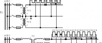
Schemes for measuring resistance using this method are shown in Fig. 4
Fig.4. Schemes for measuring winding resistance using the voltmeter and ammeter method:
a – separate winding; b – with scheme Y; c – with ∆ scheme
If the resistance of the voltmeter differs from the measured resistance by less than 100 times, then to eliminate methodological errors, the true value of the resistance is calculated using formula (1):
,
where U
– measured voltage drop, V;
I
– measured current, A;
r
in – input resistance of the voltmeter, Ohm.
Measurement of the resistance of multiphase windings in the presence of terminals of the beginnings and ends of the phases is carried out phase by phase, and in the presence of separate terminals from parts of the phases - separately for each part.
If there are no terminals for the beginnings and ends of the phases, then the resistance should be measured between each pair of linear terminals. When connecting the phases in a star (Fig. 4, b), the phase resistance r
1 adjacent to pin C1 is determined by formula (2):
r
1 = (
r
31+
r
12 –
r
23)/2,
where r
31,
r
12,
r
23 – resistances measured respectively between terminals C3 and C1, C1 and C2, C2 and C3, Ohm.
When connecting the phases in a triangle, the phase resistance r
1 between terminals C1 and C2 (Fig. 4, c) is determined by formula (3):
.
Using similar formulas with circular rearrangement of the corresponding indices, the resistances of other phases are calculated.
When the resistance of the voltmeter circuit at a given measurement limit is so large compared to the measured resistance that the current consumption in the voltmeter can be neglected, the required resistance R can be found:
R=U/I.
When using a single bridge for measurements, the resistance of the contacts and connecting wires is added to the desired winding resistance, and therefore a single bridge is recommended for use when measuring resistances exceeding 1 Ohm. The use of a double bridge ensures the highest accuracy of resistance measurements.
The thermal state of various parts of the winding is monitored using temperature sensors installed on the winding. In this case, the arithmetic mean value of the sensor readings is taken as the winding temperature if these readings change by no more than 1°C per hour and differ from the average value by no more than 2°C.
Determination of winding resistance to direct current in a practically cold state is provided for by the acceptance test program, although most electrical machines are not equipped with winding temperature sensors. In this case, the temperature of the windings is determined in the following ways:
in an electric machine equipped with temperature sensors for its individual parts, the arithmetic mean value of the sensor readings is taken as the winding temperature if it does not change by more than 10C in 4 hours when the winding resistance changes by no more than 0.5%;
in an electric machine not equipped with temperature sensors, the winding temperature is taken equal to the temperature of the surface of the machine (casing), if this temperature changes by no more than 10 C in 8 hours when the winding resistance changes by no more than 0.5% during the same time;
in an electric machine not equipped with temperature sensors, the winding temperature is taken equal to the ambient temperature during measurements, if before that the machine was inoperative for a long time, during which the ambient temperature changed by no more than 50 C.
MEASUREMENT OF INSULATION RESISTANCE OF ELECTRIC MOTOR WINDINGS.
If the motor is not put into operation immediately after delivery, it must be protected from external factors such as humidity, temperature and contamination to prevent damage to the insulation. Before turning on the motor after long-term storage, the insulation resistance should be measured.
If the motor is stored in high humidity conditions, regular measurements should be taken. It is practically impossible to formulate any standards for the minimum actual insulation resistance of an electric motor, since the resistance depends on the design features of the electric motor, the insulating material used and the rated voltage. Based on operating experience, the minimum insulation resistance can be taken equal to 10 MΩ.
Insulation resistance measurement is carried out using a megohmmeter - an ohmmeter with a high resistance range. The resistance is measured: between the windings and the “ground” of the electric motor, to which a constant voltage of 500 or 1000 V is applied. During the measurement and immediately after it, dangerous voltage may be present at the terminals, they CANNOT BE TOUCHED.
Insulation resistance:
The minimum insulation resistance of new windings or windings after cleaning or repair to ground is 10 MΩ or more.
The minimum insulation resistance, R, is calculated by multiplying the rated voltage, U n, by a constant factor of 0.5 MΩ/kV. For example: if the rated voltage is 690 V = 0.69 kV, the minimum insulation resistance is: 0.69 kV ½ 0.5 megohm / kV = 0.35 megohm
Motor insulation resistance measurement:
The minimum insulation resistance of the windings to ground is measured from 500 V DC. The winding temperature should be 25°C +/– 15°C.
The maximum insulation resistance should be measured from 500 V DC at an operating winding temperature of 80 -120°C depending on the motor type and efficiency.
Checking the insulation resistance of the motor windings:
If the insulation resistance of a new electric motor, an electric motor after cleaning or repair, which has not been used for some time, is less than 10 MOhm, this can be explained by the fact that moisture has entered the windings and they need to be dried.
If the motor is operated for a long period of time, the minimum insulation resistance may drop to a critical level. The engine remains operational if its insulation resistance has dropped to the minimum design value. However, if such a drop in resistance is detected, the electric motor must be stopped to eliminate the possibility of injury to operating personnel from stray currents.
Source: energo.ucoz.ua
Insulation resistance standards for electrical machines
The PUE (electrical installation rules) regulates the insulation resistance of electric motors depending on the design and power of the device.
Permissible resistance when testing the insulation of asynchronous electric machines
When measuring the insulation of asynchronous motors, the star or delta connection of the stator windings must be disassembled and each coil must be checked relative to the housing and to each other. Tests are carried out at a machine temperature of 10-30°C.
The insulation resistance should be:
- in the stator no less than 0.5 mOhm;
- in a wound rotor no less than 0.2 mOhm;
- The minimum insulation resistance of temperature sensors is not standardized.
In order not to use the reference book, the usually acceptable resistance is considered to be 1 mOhm. Smaller values indicate minor violations that will eventually lead to failure of the electric machine.
Important! In order to avoid such a situation, it is advisable to send the device to a specialized enterprise for medium repairs.
DC Motor Insulation
To check the insulation in DC machines, it is necessary to remove the brushes from the brush holders or place insulating material under them.
The measurement is carried out between different parts of the electrical machine circuit:
- field windings and armature commutator;
- brush holder and device body;
- armature commutator and housing;
- field windings and electrical machine housing.
Important! If possible, the field winding coils are disconnected from each other and checked separately.
The minimum permissible insulation resistance depends on the temperature and rated voltage of the electrical machine. At 20°C it is:
- 220V - 1.85 mOhm;
- 440V - 3.7 mOhm;
- 660V - 5.45 mOhm.
In addition to the windings and armature, the resistance of the excitation and armature winding bands is measured. It is checked between the bandage itself and the body, as well as the winding secured by it. It should not be less than 0.5 mOhm.