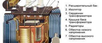
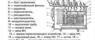
Clamp meter
Electrical clamps for electrical installations with voltages up to 0-66 kV are tested with a voltage of 2 kV for 5 minutes, clamps up to 10 kV with a voltage of 40 kV once every 24 months.
| Working with insulating pliers.| Current clamp type Ts-90. |
Electrical clamps are designed for short-term measurement of current or active power in alternating current circuits without breaking the electrical circuit. They are a complete device consisting of a current transformer with a detachable magnetic core and one secondary winding and a measuring instrument - an ammeter or wattmeter. The primary winding of this current transformer is a current-carrying conductor, covered by a detachable magnetic core when measuring current. The secondary winding, located on the magnetic core, is connected to an ammeter or to the current winding of a wattmeter.
| Electrical clamps from APRA. |
Electrical clamps are used to measure current without breaking the electrical circuit.
Electrical clamps are designed to measure current, voltage and power in electrical circuits without damaging their integrity.
| AC current clamp meter. |
An electrical clamp is a device designed to measure electrical quantities: current, voltage, power, phase angle, etc. - without breaking the current circuit or disrupting its operation. According to the measured values, clamp-on ammeters, ampere-voltmeters, wattmeters and phase meters are used.
Electrical clamps are used in installations up to 10 kV inclusive.
Electrical clamps for installations of 2 - 10 kV have an insulating part length of at least 38 cm, and handles - at least 13 cm. The dimensions of clamps up to 1000 V are not standardized.
Electrical clamps are designed to measure current, voltage and power in electrical circuits without damaging their integrity.
Electrical clamps can be used in closed electrical installations, as well as in open ones in dry weather.
Electrical clamps are designed to measure current, voltage and power in electrical circuits without damaging their integrity.
Electrical clamps D90 are designed for measuring power without breaking the current circuit in low-voltage alternating current circuits of industrial frequency.
Electrical clamp meters are designed to measure current, voltage and power in electrical circuits without disturbing the... The principle of operation of clamps is that the current is measured by a transformer, the secondary winding of which is closed to the measuring circuit. The primary winding is a bus or wire carrying the current being measured.
The principle of action of ticks
The first current measuring instruments of this kind were a kind of transformers, to which an ordinary ammeter was connected. The clothespins themselves, which are the visible part of the device, also represent the primary winding of the transformer. When a conductor carrying current is placed in it, due to its electromagnetic field it will be induced into this winding. After this, the electric current will go to the secondary winding. Indicators will be taken from it.
The process of measuring electric current in the panel using the multifunctional device AKTAKOM - ATK-4001
Important! The first types of these devices were a simple addition to measuring instruments and helped to more conveniently fix the wire being measured.
The values that the ammeter showed had to be calculated additionally, since it was necessary to take into account the transformation ratio. One more nuance: work only with alternating current, since transformers do not work with constant values.
You may be interested in this Features of wire strippers
Modern current clamps can work with any type of electric current, but to measure constant values, instead of an ammeter, they use a Hall sensor, which allows them to record the electromagnetic field and its strength.
Device complete with instruction manual
Varieties
This tool allows you to measure almost all electrical parameters, for example voltage or current. In this case, the operation of the network does not change during the process, and it does not break. Devices are divided into several types depending on the measured quantities:
- ampere-voltmeter;
- wattmeter;
- ammeter;
- phase meter;
- ohmmeter
The most popular are current clamps, which are necessary to determine the alternating current in a conductor. They take into account the physical processes of a current transformer, which has two windings. The first is a bus with measured parameters, and the second is connected to a special magnetic circuit.
Types of current clamps
Depending on the circuit used and even the appearance of the device itself, electrical clamps are divided into several types:
- Switches. An analog type device, the active part of which is a single-turn AC transformer, and the measuring device is connected to its secondary winding. These are one of the first models of current clamp meters - they are distinguished by their low cost and clear display of measurement results in the case of variable current. A common disadvantage of such devices is their high sensitivity to mechanical vibrations - if the device is not placed on a hard surface, the measurement result may be displayed incorrectly. Also, to use such devices you need a certain skill - you often have to manually convert the ammeter readings into real values in accordance with the transformation ratio. This device is also designed for a certain frequency of electric current.
- Digital. The display of readings on such a device is determined by a microcontroller, which automatically performs all the necessary calculations and (depending on the model) can be configured to directly display current or power.
- Multimeter. A universal all-in-one device - the measuring clamps are built directly into the body of the device, which makes it easy to use. The number of functions and measurement methods is determined by the model of the multimeter, so the correct name for the device would not be an electric clamp with a multimeter, but vice versa. Often such devices work with a Hall sensor, so they can be used as DC current clamps.
- High voltage. The main application is electrical circuits with standard frequency current and voltage exceeding 1 kV. Such devices have increased insulation resistance and can additionally be mounted on a dielectric rod so that the operator does not come close to the conductor from which measurements are taken. This is a specialized professional device that is designed for only one single function - measuring alternating current. If it is necessary to measure the direct current, other devices and methods are used.
How to use a clamp meter
To make the necessary measurements, you need to perform the following steps: using the function switch, select the measurement mode; then open the pliers by pressing the bracket. Then we grasp only one conductor, while placing the pliers perpendicular to the plane of the conductor; release the clamp, closing the pliers and closing the magnetic circuit of the device; look at the readings on the display.
The data lock button helps when working in hard-to-reach places. Clicking on it records the result of the latest measurements.
For example, to measure the load on a 220V network in an apartment, the range switch in the current clamp is set to AC mode with a value of 200. Then, at the input, we wrap the clamps around the insulated conductor. We record the readings that appear on the display. We multiply this value by the voltage in the network - 220V. For example, the value 10A appeared on the display. We calculate the load in the network using the formula: P = I ×U, P = 10 × 220 = 2200 W = 2.2 kW. The resulting value can be used to check the operation of the electric meter.
If you grasp several wires, the device will show the sum of the currents covered by the clamps. For example, if you capture the phase and neutral wires at the same time, the device will show a zero value, since the currents of these conductors are equal in magnitude, but opposite in direction. The appearance of other values indicates a current leakage equal to this value.
The appearance of the number “1” on the display during measurements indicates that the current value in the conductor is outside the set measurement range. Therefore, using a switch it is necessary to increase the range of current measurements.
If you need to measure a small current value, you can make several turns of the conductor around the open clamps. Set the range switch to the minimum value. The number that appears on the display must be divided by the number of turns of the conductor - this will be the actual value of the current.
We recommend to your attention: using a voltage indicator.
Current clamps: how to use
If you know how to use a multimeter, then it would seem that it could be difficult when working with current clamps. However, there are still some difficulties, as it turns out. And if you are one of those who just bought pliers and when you try to use them, you get a zero value on the screen, then join the instructions that will help you learn how to use the tool correctly. First, let's look at some features on which correct operation depends:
- If several conductors of a three-phase circuit are placed inside the magnetic circuit, the device will display the total current value.
- It is necessary to measure the current in a single-phase circuit for one wire. If you place several wires inside at once (phase and neutral), the value on the display will be zero. You've probably already encountered this when you tried to check the current strength in the wire from an electric kettle or other household devices.
- If you place three wires of a three-phase circuit inside the magnetic circuit at once, the result will also be zero.
Having found out the features of using current clamps, you can resort to their operation. This is done in the following way:
- Inside the magnetic circuit ring there is one of the wires that powers the electrical equipment. It is very important that exactly one wire of a single-phase circuit is located inside, since otherwise it will not be possible to carry out measurements.
- Close the magnetic circuit ring.
- Set the rotary indicator on the device to the ACA or DCA position, depending on the type of circuit. What value should the pointer be set to? Beginners are often confused about this issue. So, the device usually has several current values for measurements. This can be up to 20A, 200A or 1000A. To find out what value you need to set the pointer to, we estimate the power of the equipment whose current you need to know. If this is a 2 kW kettle, then it should be 2000 W / 220V, and we get a value of 9A. This means that the device can set the measurement value in the range of up to 20A, and thereby obtain the most correct result. In order not to carry out calculations, we set the pointer to the maximum value and measure. Based on the results obtained, we move the regulator to a smaller range.
To avoid any difficulties, we will learn how to use current clamps using an example.
- We use a 50 liter water heater/boiler as electrical equipment.
- The boiler has a power setting of 1.5 kW. We need this value to check the accuracy of the measurements and the error of the device.
- To find out the current that the water heater consumes, you need to place the power wires in a current clamp. To do this, remove the protective cover from the circuit breaker and gain access to the required wire.
- The blue wire goes through the circuit breaker, and the black wire is used to check the current strength. We set the appropriate measurement range on the device (in this particular case we use clamps of the Clamp Meter 266 model) up to 200A.
- Next, we place the conductor inside the magnetic circuit of the device.
- And we turn on the water heater to the network. We take the obtained values.
- This is the value of the current consumed by a single-phase boiler with a power of 1.5 kW. We remember it using the Data Hold key.
- Now, in order not to forget this value, you can write it down on paper.
With these simple steps we were able to calculate the amount of current consumed by the boiler. We make sure that these values are correct. To do this, the boiler power of 1500 watts must be divided by the network voltage of 220 volts. We get a value of 6.8 Amperes. A slight error in tenths of Amperes is due to voltage drops. To get more accurate results, you should also measure the voltage in the circuit with the boiler on.
In this way you can determine the current strength for any household electrical appliance or construction tool. When using current clamps, it is important to consider the following features:
- To get the most accurate readings, it is necessary to place the wire inside the clamp so that it touches the magnetic core.
- If the power of the equipment whose current is measured is very low, then several turns of wire should be made around the magnetic core of the device. The result obtained should be divided by the number of turns in order to ultimately find out the correct current value.
The video below shows a simple video instruction on how to learn how to use current clamps.
It is also worth noting that the lower the current in the conductor, the higher the degree of error. If during a measurement the value “1” is displayed on the instrument display, this indicates that the current strength in the conductor is higher than the range set on the instrument. To do this, you need to move the switch to the next measurement boundary.
This is interesting! It is recommended to check the instrument before taking measurements. To do this, inspect the device for integrity. Turn it on and make sure it works. Measure the current value on electrical equipment whose amperage is known to ensure that the reading is correct. Only then proceed to measurements.
Construction and tension
Depending on the voltage of the electrical networks in which current clamps are used for measurements, the design of these devices can be adapted accordingly. Thus, in electrical networks up to 1000 volts, electrical clamps are used with “jaws” controlled with one hand.
But in electrical networks up to 10,000 volts, two-handed current clamps are used. This is caused by the need to remove the hands at a safe distance (from 38 cm and more) from live parts that are under high voltage. Such “jaws” are no longer a multimeter, but simply an ammeter. Moreover, many models use an analog dial gauge. Working with clamp meters at high voltage is associated with an increased risk of electric shock.
Current clamps Model of measuring “jaws” for electrical networks with voltages up to 1000 V Model of measuring “jaws” for electrical networks with voltages up to 10 kV
For this reason, only two people work with these meters in power networks up to 10 kV, and if this happens outside, then in the absence of precipitation (fog). One person holds the electrical clamp with hands wearing dielectric gloves, standing on a dielectric mat or other surface with reliable insulation. He manipulates them, and another person looks at the ammeter built into this device, standing nearby. It is prohibited to use high-voltage current-measuring “jaws” under a voltage of 2–10 kV in any other manner.
Design
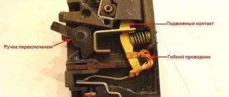
Modern current clamp meters, regardless of manufacturer and modification, contain the following elements: magnetic circuits with a movable bracket-lever, a switch for measurement ranges, a screen, output connectors for probes (in this case, the clamps can be used as a regular multimeter) and a button for fixing current measurements (photo below ).
Figure 1 – TK S-line DT 266 FT
Most modern current meters also include an internal diode bridge transformer. In this case, the terminals of the secondary winding are connected via a shunt. Depending on the range of measured currents, current clamps can be one-handed (for voltages up to 1000 V) or two-handed with additional insulated handles (for voltages from 2 to 10 kV inclusive). Current measuring devices intended for measurements of more than 1 kV have an insulator length of less than 38 cm, and handles of at least 13 cm.
As a rule, the safety category and the maximum measured current are indicated on the device body. For example:
- CAT III 600 V - this means that the device is protected from short-term voltage surges inside the equipment when operating in fixed networks with voltages up to 600 V.
- CATIV 300 V - this means that the device is protected from voltage surges inside primary power supply equipment with voltages up to 300 V. An example of such equipment is a conventional electric meter.
What it is
Electric clamps directly serve specialists for prompt and reliable measurement of various parameters of electric current: its voltage, power and others. In this case, there is no need to break the chain or disrupt its operation. Depending on what values need to be measured, the following mites are distinguished:
- Ammeter;
- Ampere-voltmeter;
- Wattmeter;
- Phase meter.
Current clamps
This measuring device in any configuration - from the simplest to the most professional - consists of a magnetic core, a button that records measurement data, a switch (for selecting the measurement range and the necessary additional functions of the device), various connectors for additional connection of probes and a small built-in monitor/ display.
Current clamps
The most popular and also easily applicable are clamp-on ammeters, used to obtain the parameters and characteristics of alternating current; they are also called current meters. Let's figure out why current clamps are needed.
Electrical clamps easily allow you to:
- Determine and control actual loads in electrical networks;
- Measure the power of various electrical appliances;
- Monitor the operation of electricity meters and its consumption (for example, to verify electrical meter readings).
Important! Such current clamps can be used at voltages up to 10 kilovolts
Instructions for use
Almost all current clamps on the market today are digital. Let's take a closer look at how to use a clamp meter. Let's look at this using the example of a digital and analog device.
Digital clamps M266
The device is professional. It consists of a digital display on liquid crystals, which displays all measured indicators, and a circular rotary switch. Its scale shows the main parameters of the measurement limits and their values in the required range. The main working part of the device is the pliers themselves (the pliers are the transformer).
The picture above shows the control panel of the M266 digital clamp meter.
And the figure below shows the supplied equipment of this device.
The device has current measurement limits of 20A, 200A and 1000A. Digital measuring clamps M266 are equipped with a multimeter with probes. With their help, you can measure voltages up to 1000 Volts DC and 750 Volts AC. The device can be used to check the serviceability of semiconductor diodes, use the device to test electrical circuits, and measure temperature. These current clamps can also measure the insulation resistance of conductors up to 2000 MOhm.
About the M266 clamp meter, watch the video below:
Analog clamps Ts4501
This measuring device uses the same principles of physics to take measurements as a digital clamp meter, but its functionality is slightly lower. The device has measurement limits for current - 10A, 25A, 100A, 250A and 500A, for voltage 30V and 600V, for resistance 2 kOhm. But it cannot measure insulation resistance and temperature. In all other respects, it is not inferior to a digital device.
How to take measurements
In order to carry out a measurement with a digital current clamp, you must perform the following operations:
- Turn on the device and set the rotary switch to the desired sector of the measurement limit;
- Insert a conductor between the magnetic-carrying transformer clamps;
- Wait for the measurement results to appear on the display.
When carrying out work on measuring voltage and current in electrical networks using current clamps, it is necessary to remember the following subtleties of such work:
- If the parameters displayed on the device display are not correct, make sure that you have chosen the correct measuring range for working with the device. When taking measurements with a dial gauge, the needle may go off scale;
- In order for the use of a measuring device to give the most accurate results, it is recommended to use the following measurement method: take several turns of the conductor being measured in a pliers (this must be done by first de-energizing this conductor and checking the absence of voltage with an indicator), and after applying voltage, divide the obtained measurement results by the number of turns , thus, the result obtained will most accurately reflect the actual operating current;
- Strictly follow all safety precautions when working with live circuits.
Clamp meter
Hello, dear readers and guests of the Electrician's Notes website.
In previous articles, we got acquainted with insulating mites. Today I will tell you in detail about electrical clamps.
Please do not confuse these two phrases, because they are not the same thing. However, you will see this for yourself now.
Electrical clamps are used to measure current in electrical installations with voltages up to 10 (kV), as well as to measure voltage in electrical installations up to 1000 (V) without breaking the controlled circuit.
Electrical clamps apply ONLY to the main means of protection in electrical installations up to and above 1000 (V).
Design of electrical clamps
Almost every electrician probably knows what an electrical clamp looks like.
Electrical clamp meters have a built-in current transformer. The current transformer has a detachable magnetic circuit.
The primary winding is a conductor carrying the measured current. An electrical measuring device is used as the secondary winding.
Currently, there are a large number of electrical clamps of various types and models. Depending on the type and model of the clamp, the electrical measuring device can be either analog (pointer) or digital.
In this article, as an example, I use the M266 electrical clamp from my list of tools. I like them for their simplicity and reliability.
Electrical clamps up to 1000 (V) consist of a working part and a housing. The working part is used:
The body itself with a stop and a handle is used as the insulating part of the pliers.
Clamp meters above 1000 (V) consist of:
- working part
- insulating part
- handles
The working part of the pliers is a magnetic circuit, a winding and an electrical measuring device, which can be either removable or built-in in an electrically insulating housing.
The insulating part of electrical clamps above 1000 (V) must have a length of at least 38 (cm), and the handle must be at least 13 (cm).
Clamp meter testing
During operation of electrical clamps, it is necessary to carry out electrical tests on them. According to the Instructions for the Use and Testing of Protective Equipment Used in Electrical Installations (IPISZ), Appendix 8, the frequency of testing electrical clamps is once every 2 years (24 months), and the test duration is 5 minutes.
A test voltage of 40 (kV) is supplied between the magnetic core and a temporary electrode, which is installed near the limiting stop on the side of the insulating part. This applies to clamp meters up to 10 (kV).
For clamps up to 1000 (V), a test voltage of 2 (kV) is applied between the magnetic core and the base of the handle.
How to use?
When measuring circuit parameters, the electrical clamps must be kept suspended. It is forbidden to lean towards the electrical clamp meter to take readings.
In an electrical installation up to 10 (kV), it is prohibited to use remote devices, as well as switch measurement limits. To switch the limit, you need to remove the clamps from the live part.
It is prohibited to use electrical clamps on overhead line supports up to 1000 (V), unless the clamps are specifically designed for this.
Let me give you a clear example. Let's say that we need to measure the magnitude of alternating current. To do this, you need to switch the clamp limit to “ASA”, separate the magnetic circuit and wrap around the conductor (wire) going to the load of interest to us. A clamp meter will show us the amount of current in this conductor.
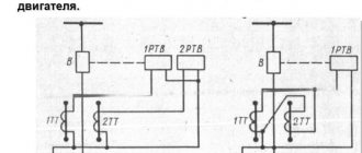
In my example, I did it a little differently. On a test bench to test relay protection, using a current source, I induced about 5 (A) in the conductor. This can be seen on the ammeter.
Now let’s check the current in this conductor using an electrical clamp.
The measured current using an electrical clamp was 5 (A), which corresponds to the value of the previously induced current.
Instead of electrical clamps, you can use a multimeter, or “tester”, as many call it. To do this, I have prepared a whole course for you, consisting of 3 parts:
{SOURCE}
Structural elements of current clamps
Electrical clamps include the following main elements:
- connectors into which the corresponding probes are connected;
- display showing the measurement result;
- mode switch;
- tool release button;
- magnetic circuit (the clamps themselves).
When measuring direct current, the device circuit includes:
- electric current transformer;
- rectification bridge.
The secondary winding is connected to the switches with a set of shunts.
Current clamps are divided into one- and two-handed. One-handed designs combine a handle and an insulating part. Opening is carried out by a push lever. The work is done with one hand.
For two-handed devices, the size of the handles exceeds 13 cm, and the insulating part is 38 cm or more. A design feature is their use with 2 hands.
When purchasing, they are determined by choosing how to choose the necessary tool. In retail outlets there is a large assortment of these devices with different functionality, which determines their price. When purchasing, the consumer must decide on the necessary functionality, some of which may be unnecessary.
Question of price
Again, differences in price are especially clear when comparing Russian and foreign products. In the lines of budget solutions of domestic companies you can find models for 1-2 thousand rubles. Higher quality equipment that can be used to solve professional problems is estimated at 3-4 thousand rubles. By the way, budget foreign measuring clamps are in the same range. The price of professional devices from Fluke or Sturm can reach 6-7 thousand. This is the level of the same wireless technology, which is distinguished by both high measurement accuracy and durability.
Measurement modes
There are 2 methods for determining current strength:
- direct;
- indirect (inductive) measurement.
The first method is carried out by connecting an ammeter to an open circuit. An electric current passes through the device, information about the value of the I value appears on the display.
Advantages of this method:
- measurement accuracy depending on the class of equipment;
- ease and accessibility of measurements.
Flaws:
- it is impossible to measure large amounts of electric currents due to the design features;
- without a break it is impossible to measure the parameters of the circuit;
- measurements are performed only in the circuit that is connected to the device.
If the electrical clamp acts as a current transformer in the role of a secondary coil, then the inductive method is used.
Its advantages:
- safety;
- measurements of large values of electricity are carried out;
- there is no need to break the circuit to carry out measurements;
- mobility of measurements performed.
But it is not without its drawbacks:
- measurements cannot be performed in hard-to-reach places;
- for small values of the parameters being determined, there is a large error.
When using this tool, it is useful for an electrician to know some nuances that improve the quality of the operations performed.
When considering how to use current clamps when the value of I in the conductor is too small, which is not accurately detected by the tester, you need to use winding the conductor on one of the working parts of the device. The display shows information about the total indicator; the exact value is determined by the ratio of the obtained value to the number of turns.
If the electric current value is greater than the maximum possible for the tester, “1” appears on the screen. The range of measurements taken increases and they are repeated.
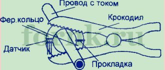
The leakage current is detected by searching for it on the grounding wire, as well as by grasping it with clamps to measure the zero and phase current. If a number other than “0” appears on the screen, then there is a leak; an insulation breakdown should be looked for on the housing.
If there is a “Hold” button, the current clamp model can measure electric current in hard-to-reach places. When performing such an action, the current clamps cover the wire, after which this button is pressed, which leads to the fixation of the value on the screen, after which it is viewed in any accessible place.
The measurement mode switch can be in different positions depending on what indicator is being measured. So, when determining direct current, it is placed in the “DCA” position, and voltage - “DCV”, for variable types - “ACA” and “ACV”, respectively. The switch also allows for continuity testing, diode and resistance testing.
The probes are connected through multi-colored connectors with different alphabetic symbols. The red wire is connected to the same connector labeled “VΩ”. The connector of the same color “EXT” is intended for connecting an insulation meter. The neutral wire is connected to a one-color connector with the symbol “COM”.
Usage example
Let's give an example of how to use current clamps when measuring load on a 220 V network, for example in an apartment. In this case, the switch must be set to position AC 200. Next, you need to grasp the insulated conductor with a current clamp and take readings. After this, the resulting current value must be multiplied by the network voltage of 220 V. For example, if the device shows 5 A, then the power consumption in the network will be P = U * I = 5 * 220 = 1100 W or 1.1 kW. The obtained value can be used to check the operation of electricity meters.
Finally, we suggest watching a video that clearly shows how to use the DT-266 and Fluke 302+ current clamps, which are quite popular today:
DT-266 Fluke 302+
That's all the instructions on how to use current clamps yourself. As you can see, there is nothing complicated. The main thing is to follow safety measures and take measurements carefully. We hope that our tips and visual video instructions clearly explained the procedure to you!
It will be interesting to read:
- How to use a multimeter - instructions for dummies
- How to check if your electricity meter is working correctly
- List of electrician's tools
Correct use of the DT-266 Fluke 302+ tool Material taken from the site: https://samelectrik.ru/
Operating principle of clamp meters
When using any method, the main principle is measurement. It is similar when using multimeters for everyday use (up to 1000 V) and professional ones (above 1000 V). Household measuring clamps are one-handed, while professional ones are mostly two-handed. It makes sense to purchase professional devices when working with high-voltage networks.
Electrical clamps connected to a multimeter allow you to perform the measurement process in the following sequence:
- a wire for measuring electric current is detected (the instrument's grasping of several wires during measurement contributes to obtaining an incorrect result);
- the range and mode of the tester are selected - if the value of I is unknown, measurements begin with the largest scale;
- place in the current clamp the conductor in which it is necessary to measure I (to achieve an accurate measurement, the wire is placed in the center perpendicular to the body of the device).
Using a simple example, you can demonstrate how to check the load on a 220 V network. The position of the clamp switch in order to measure the current is AC 200, the clamps grip the conductor, and then take readings. Find the product of the measured value and voltage. The calculated value can be compared with the values of electricity meters.
Repair and adjustment of current clamps
First of all, it should be noted that it is possible to repair current clamps if you not only have the necessary skills to work with a soldering iron, but also knowledge of electronics. A measuring instrument can fail for various reasons:
- fall from height and other mechanical damage;
- incorrect connection of the device to the circuit when measuring the corresponding quantities, for example, the switch is set to current measurement mode, and the probes are connected to the socket to measure the potential difference (voltage);
- oxidation of the battery, which floods the board, damaging parts.
Repair of current clamps depends on the nature of the fault. If a capacitor or resistor fails, they can be replaced using a soldering iron or hair dryer. You can determine the faulty element visually or by checking with a multimeter. If the microcontroller fails, then there is no point in repairing the device. In this case, it will be easier to buy new current clamps.
Regarding current clamps, it should be noted that each model comes with instructions and a corresponding technical description. Error values must be indicated between the lines. These must be taken into account to obtain accurate readings. Sometimes the error may be greater, which is also acceptable. In this case, you need to adjust the device yourself; for this, there are corresponding regulators on the board. The photo below shows what they look like.
Below is a detailed video about whether you need to buy clamp meters, or you can get by with a multimeter.
To summarize, it should be noted that learning how to use a clamp meter is not difficult, but be sure to follow safety precautions when working with the tool. Although the device eliminates the need to include it in the circuit, during measurements the possibility of a break in a conductor that can be touched by hand cannot be ruled out. If you work in networks with high voltages over 220V, it is definitely recommended to use dielectric gloves.
Recommendations for selection
To ensure that none of the workers subsequently becomes a victim of electric shock and the culprit of an accident at an electrical installation, adhere to the following recommendations.
- To purchase current clamps, contact a specialized electrical and electronics store, where experienced consultants will tell you which clamps are suitable for solving specific problems. Their experience can prevent mistakes, the consequences of which could be disastrous.
- First of all, decide what kind of current you will work with. AC/DC markers indicate that the tool is universal, DC is only for direct current on the line, AC is only for alternating current.
- Decide what power range you will be working in. Perhaps your choice is in circuits and lines with a maximum power of, say, up to 25 kW, then you are unlikely to need current clamps with a power of 500 kW if there is a product on sale for 50-100 kW.
- Decide what the diameter of the wires on which the power is measured is. Perhaps you will work on wires with a cross-section of up to 15 mm2, then you do not need larger pliers, where the cross-section size reaches 50-100 mm2, if the size on sale is 15-25 mm2.
- If we are talking about digital clamps or a device model for direct current, decide how it is more convenient for you to read the measured current: by reading in milliamps, millivolts or volts.
- Make sure that the materials of the insulating handles and the coating of the pliers do not conduct current. It should be high quality plastic, rubber or composite.
- Check the warranty service life of the pliers, make sure that in the instructions the manufacturer has indicated parameters whose value ranges include those that you need for safe and trouble-free operation.
- Refrain from purchasing pliers at too high a price - not all of their functions may be useful to you.
- If the work is mainly carried out in garage-domestic conditions, and not in production, then give preference to inexpensive pliers, from which you only need to successfully solve your specific problems. Pliers in a low price range are equipped with the function of testing lines and sections of chains.
- Avoid cheap Chinese counterfeits, which have a strong plastic smell. In some areas of the same clamps there may be extra gaps and cracks in the dielectric coating.
- If the seller has the opportunity to test the device with a current clamp, make sure that it does not exceed the stated error of the measured current, voltage and resistance in the test line.
- If you have to carry out measurements and tests in electrical installations around which there is excessive humidity, high or excessively low temperatures, choose a product that meets your specific needs.
- Focus on reviews from real customers. If you suspect that positive reviews may have been written at the request of the manufacturer itself in order to increase the rating of the product, look for reviews from other users on similar sites. Even the marketplace where you order these pliers will not provide a 100% guarantee of protection from unrealistic reviews.
- For thin wires, lightweight pliers are used. If your work does not involve contact of the device with a voltage of more than 220 volts, and the consumed currents hardly exceed 20 A, then use lightweight clamps, the cross-section of the wire soldered to the claws is equal to the ammeter shunt in a conventional multimeter.
- Make sure that the batteries in the digital device (to power the multitester) are easy and quick to replace.
Make sure the clamp device provides:
- measurement of current and voltage surges when starting powerful engines;
- automatic switching of measurement ranges, which saves time when taking measurements;
- if the display is large enough and backlit, this allows you to work on the line even at night.
Security measures
When working with such equipment, you should adhere to the general safety rules for operating electrical measuring instruments, despite the fact that the use of current clamps is a safe procedure. It is prohibited to exceed the value of the selected electric current range and change the range during the measurement process. You should also not hold bare probes with unprotected hands that are not protected by a dielectric.
A lamp is an example of a device operating at alternating current from 220 V
Before using any device, you should carefully study the operating manual and all instructions. This helps not only not to expose yourself to danger, but also to extend the life of the device. This is very important, since the manual describes the setup of the device, its operating modes, and the principles of its safe use. Moreover, such manuals tell you how long and how to calibrate the device. It is done in specialized centers, and is needed to increase the accuracy of the measured parameters.
You may be interested in Checking the Ku202n thyristor
Current meter with protective handles for high voltage networks
Thus, a DC current clamp meter is a convenient and practical tool for determining the strength of electric current without breaking the wires, as is done with an ammeter or multimeter. With its help, you can measure the electric current in a car and its wiring, at home and at sites where the electrical network is laid, installed or maintained at any time.
Insulating and electrical clamps
Insulating and electrical clamps are divided into two main types depending on the power of the electrical network in which they are planned to be used. So, one-handed ones are used for networks up to 1 kV, two-handed ones - for networks over one and up to 10 kV. The use of two-handed electrical clamps allows you to take measurements without disconnecting the network. Special requirements are imposed on two-handed pliers: for example, the insulating part in them must be no shorter than 0.38 m, and the length of the handles cannot be less than 13 cm. For one-handed clamps used for networks up to 1 kV, there are no such strict standards.
How do clamp meters work and how to use them?
You need to open the pliers and wrap them around one wire (this can be either phase or zero). Close the clamps and look at the resulting value of the measured value on the screen. In cases where it is necessary to measure current in a hard-to-reach place, a button is used that allows you to record the readings of the device. This means that the value can be viewed after the pliers are removed from a hard-to-reach place. These pliers can be used in both open and closed installations. If measurements are made for equipment located outside, the weather should be dry, without precipitation.
When working with pliers, be sure to use dielectric gloves. In addition, the person taking the measurements must be on a current-insulating surface. During intensive use, pliers must undergo a high-voltage test once every two years.
If you are purchasing pliers for home use, pay attention to the manufacturer's inspection stamps. But according to the rules for operating electrical installations, only specially trained people with a safety group of at least fourth have access to working with electrical clamps
It is optimal when two people take part in the measurements: the first one takes measurements, and the second one reads and records the readings of the device.
When choosing electrical clamps, you should pay attention to the quality of the materials from which they are made. As a rule, Chinese equipment costs much less, but it is usually made from low-quality plastic and rubber, which have a strong unpleasant odor
Such a device is unlikely to serve you for a long time. On the other hand, if you are purchasing a device for home use, you should not get hung up on a large number of functions, in this case the device will cost more, and you are unlikely to use it to its fullest. A device that can determine current strength, resistance and voltage is sufficient for the home.
← Previous page Next page →
How to measure correctly with current clamps
The error when measuring small currents is quite large, and it is larger for automatic clamps. However, when the current exceeds 1 A, this error decreases. From this we can conclude: it is better to check small currents with a multimeter, and large ones with clamps.
Those who do not know how to use a clamp meter can measure an entire cable and get a result that is almost zero, although in fact there is current flowing through the cable.
This happens because the same current flows through the phase and neutral wires Due to this, their magnetic fields oppose each other, resulting in a zero. Therefore, the measurement is performed on only one conductor.
This is a significant drawback, since it is not always possible to find a disconnected cable. Typically, disconnection occurs in machines and at the input.
In all other cases, you can use a small extension cord with the wires disconnected. The device under test is connected through an extension cord and measurements are taken. This is especially convenient when you need to measure too little current.
Kinds
Today in the electrical equipment markets you can find a great variety of variations and modifications of current clamps. However, here you should not be guided by the principle “what is more expensive is better”, because the most expensive models are stuffed up and down with a great variety of functions, the purpose of which even professional electricians, let alone ordinary people, do not know. For everyday use at home, it is enough to purchase a device that can measure current, voltage and resistance. However, you shouldn’t save too much on such a device, because you can end up with a low-quality Chinese copy, which may have a high measurement error, a bad case with an unpleasant odor and sticking glue. Let's see what types of devices can be found in stores and what they can be suitable for.
Various models of electric pliers
High voltage current clamps
Of course, in everyday life the most common models are current clamps that are capable of measuring current up to 1 thousand volts. However, in industrial conditions there is often a need to study current parameters above 1000 V. It is for such situations that high-voltage current clamps were made. In essence, their design is no different from other models of these devices, but they have very high and reliable insulation to protect the person measuring from injury.
Current clamp with multimeter
This device is perhaps the most modern of all electrical appliances currently available on the market. This is like 3in1 coffee, only from the world of electricity! This small device contains a great variety of functions: in addition to basic current measurement, it is capable of obtaining data on voltage, capacitance, frequency, and resistance. In such devices, as a rule, the measurement error is minimal. They can measure current over very wide ranges. If there is a need to monitor the waveform, this device provides an analog output for connecting oscilloscopes.
Clamp multimeters
Digital current clamps
This device has a high degree of automation. This means that it is capable of determining the necessary modes itself depending on external conditions, as well as setting precise measurement limits. As a rule, they have a non-contact voltage tester and a convenient digital display with backlight function, and are manufactured in a reliable rubberized case.
Some of these devices are also capable, like the previous type, of receiving data on voltage, capacitance, frequency, resistance, temperature, duty cycle, checking diodes, and “testing” circuits. They have a “Data hold” function: you can save the measurements obtained after opening the clamps and keep a data log
They run on regular batteries and are very small in size and weight (about 200-300 grams). Ideal for electrical installation work.
Current clamps with dial indicator
Such electric pliers can rightfully be called the forefathers of all the subspecies described above. This device was the first to use the transformer principle to measure direct and alternating current. In them, instead of a convenient digital display, the data is displayed on a pointer mechanical panel, which is why they significantly lose in convenience and ease of use. However, they have a small measurement error, which is why they have not lost their popularity and competitiveness in the market in our age of digital devices.
Switch clamps