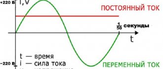
Connection diagrams for voltage transformers in open and open delta
An open delta connection means that the equipment is connected between the sides of two phases. In this case, electric current is conducted from the outside, from the secondary windings of a number proportional to this indicator. The relay and the main load are connected between the secondary network, which allows you to obtain the desired level of resistance.
This circuit allows you to connect three sources at a time. It should be noted that the supply is organized in a linear manner, and the passage of current from the first to the third source and vice versa must be avoided.
The open type of connection is used in rectifier equipment. Using a type connection, a current of triple frequency is achieved, which is impossible when working with a star or open symmetrical. An option is used when three transformers with one phase are connected to a device that increases proportionally the three operating frequencies.
Using the figure under consideration, a zero sequence is obtained, that is, in the normal functional UP will be equal to zero.
The neutral of the primary winding must be grounded, and for the secondary winding, parameters of at least 100 Volts are selected, if grounded. For an isolated one, the coefficient is taken to be 100 to 3 V. The coefficient is three times, therefore, the secondary windings sum up the transformation coefficient also three times. Therefore, for the example described above, it is 6 thousand to one hundred to three. The peak is obtained from the transformer windings of the outer surface, since the supply is carried out through the secondary. Grounding is required.
On the contrary, there is a risk not for the device, but for the personnel who service it. In production, it is strictly prohibited to install protective or switching equipment between devices of this type.
B) Connection diagram of voltage transformer windings in an open delta
Consequently, a voltage proportional to the zero-sequence voltage is obtained at the terminals of the open delta.
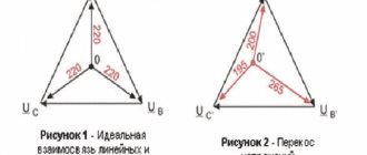
Under normal conditions, the phase voltages are symmetrical and equal to zero in total. Therefore, in normal mode Uр = 0.
With short circuit without ground, the sum of the phase voltages is always zero, because in this case the voltage vectors do not contain a zero-sequence component. Therefore, the voltage U in this case is also zero. And only in case of ground faults the geometric sum of the phase voltages relative to the ground is not equal to zero due to the appearance of the U 0 component in them.
As a result, a residual voltage appears at the terminals of the open triangle equal to U p
=
3 U 0 /mon.
The direct and negative sequence voltages form symmetrical stars and therefore, when summed in an open triangle circuit, they always give zero at its terminals.
Thus, the considered circuit is a filter that passes only zero-sequence voltage. The considered connection diagram is very convenient and has become widespread in practice.
A necessary condition for the operation of the considered circuit as a filter U 0 is the grounding of the neutral of the primary winding of the VT.
In the absence of grounding to the primary windings of the VT
instead of phase voltages relative to the ground, phase voltages relative to the isolated neutral will be supplied (see § 6-3, a).
These voltages do not contain U 0 ,
and their sum is always zero. Therefore, during a ground fault, there will be no voltage at the output of the circuit.
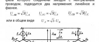
Using single-phase voltage transformers with two secondary windings, you can connect one secondary winding in a star circuit, and the second in an open delta (Fig. 6-11) and thus obtain three types of voltage from one voltage transformer: phase, phase-to-phase and zero sequence .
The rated secondary voltage of the winding intended for connection in an open delta is assumed to be equal for networks with a grounded neutral of 100 V and for networks with an isolated neutral of 100/3 V.
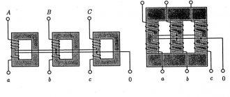
d) Connection diagram of the windings of three-phase voltage transformers into a zero-sequence voltage filter
To obtain zero sequence voltage from a three-phase five-rod transformer (Fig. 6-8) on each of its main rods 1, 2 and 3
an additional (third) winding is performed, connected, as in the previous case, according to an open triangle circuit. The voltage at the terminals of this winding appears, as in the previous case, only during a short circuit. to the ground when zero-sequence magnetic fluxes arise, closing along the fourth and fifth magnetic cores.
Circuits with a five-rod transformer shown in Fig. 6-8, make it possible to obtain phase and phase-to-phase voltages simultaneously with the zero-sequence voltage.
Difference between connections
The main difference between an open triangle and an open one is that it can be used to obtain a zero-sequence voltage. In the case of an open connection, the values of the secondary terminals are always proportional to the phase-to-phase value.
But in any case, circuit breakers and fuses are used to protect transformers with such a circuit. If a phase is broken, a short circuit occurs.
Blocking with the help of automatic machines will avoid a surge, which leads to winding malfunctions. Control is carried out with the possibility of measurement.
In what cases is it used?
The schematic construction of an open-loop version for a transformer is used quite often in production. The fact is that thanks to it you can use synchronization on power vehicles. Used to connect transformers with one phase if it is not possible to install a three-phase one. Protects mechanisms, including electric motors, from supplying two if there is no voltage in one of the phases. The only acceptable assembly scheme is if the rotor is installed in the stator bore.
Open triangle. Open triangle
Publication date: July 17, 2013. Category: Articles.
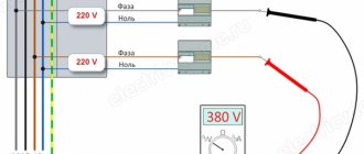
It is necessary to distinguish a connection into an open triangle (Figure 1, a) from a connection into an open triangle (Figure 1, b), sometimes called V-shaped. Let's look at a few typical examples of their areas of application.
Figure 1. Difference between connections into open (a) and open (b) triangles. Examples of using open delta connections: frequency tripler (c) and zero sequence voltage filter (d).
Open triangle
An open triangle is used, for example, in rectifier installations to produce a triple-frequency current that biases an equalizing reactor (see the article “Six-phase star and double zigzag”, Figure 3, a) For this purpose, a frequency tripler , which consists of three single-phase transformers with highly saturated magnetic circuits. The primary windings of the frequency tripler are connected in a star with an insulated neutral, the secondary windings are connected in an open triangle (Figure 1, c). The strong saturation of the magnetic circuits, their low magnetic resistance, the impassability of the neutral of the primary winding for third harmonic currents - all this ensures the appearance in the secondary windings of an electromotive force (emf) of triple frequency, coinciding in time for all phases (see the article “The Concept of magnetic equilibrium of the transformer"). Therefore, a triple-frequency current passes through the UR, which closes the circuit of the secondary windings of the frequency tripler, which is what is required in this case (see the article “Six-phase star and double zigzag”).
Scheme - open triangle
To monitor the insulation resistance and power supply of the protection triggered during a ground fault, there are additional windings that are connected according to the open delta circuit ADHD.
In symmetrical mode, the sum of the EMF induced in these windings is zero. If one of the wires is grounded, the EMF balance is disrupted and a voltage appears at the terminals of the open triangle, which is supplied to the sound alarm. [16] To supply the power direction relay with a voltage equal to the sum Ob - - Oc, an additional terminal I, provided in an open delta circuit, is usually used. For the purpose of convenience of checking the protection using an additional (test) conductor during installation, terminal I is connected to the clamping row of this panel. [17]
At the same time, the refusal of accurate measurement in case of double ground faults simplifies the protection circuit and allows us to limit ourselves to installing two current transformers per line and two single-phase voltage transformers connected according to an open delta circuit. [19]
The rated current of a non-selective circuit breaker installed in a circuit of remote loads is recommended to be 2 5 A. The rated current of a circuit breaker installed in the wires and additional VT windings connected in an open delta circuit (see Fig. 4.4) is also assumed to be 2 5 A. [20]
This protection kit can be connected using a step finder 9 to the zero sequence current transformers of each line. The stepper finder is started using a voltage relay 10 connected to the auxiliary winding of the voltage transformer 11, connected according to an open delta circuit. [22]
Grounded single-phase voltage transformers, which are used in networks with an isolated and compensated (connected to the ground through an arc suppression reactor) neutral, find themselves in special conditions. Due to the single-phase ground faults characteristic of such networks, they have, as indicated, auxiliary windings connected according to an open delta circuit. [23]
The electric motors of machine tools are protected from short circuits using fuses. To protect electric motors from operating on two phases in the event of a voltage failure in one of the phases, the installation of two intermediate relays is provided, connected after each group of fuses according to an open delta circuit. [24]
In the first case, the middle point of the linear windings of the power transformer is grounded through the linear winding of the communication transformer 2, and the telemechanics modem 3 is connected to the secondary winding of the communication transformer. When using a three-phase measuring voltage transformer, for example NTMI-10 (Fig. 4.11 6), as a connection element, the telemechanics modem 3 is connected to the secondary windings 9, connected in an open delta circuit. In the diagram in Fig. 4.11 and the signal from the output of modem 3 through the linear winding of the communication transformer 2 is supplied to the phase wires of the overhead line through the midpoint of the linear windings 6 of the power transformer /, connected in a star configuration. In the diagram in Fig. 4.11 6 the signal from the output of the modem is supplied to the secondary windings 9 of the measuring transformer 4 and is transformed through the linear windings 8 to each phase wire of the overhead line. [26]
The voltage 3U0 under normal conditions is created artificially - by eliminating one of the phases of the voltage transformer. However, this is not always possible due to local conditions. Therefore, they are often limited to excluding from the open delta circuit one of the additional secondary windings directly at the LV terminals of the voltage transformer. [27]
In Fig. XI.3 shows the connection diagram for single-phase three-winding voltage transformers. The zero of the HV windings in these circuits is grounded, and both phase-to-phase and phase-to-phase voltages can be obtained from star-connected transformers. Additional windings of transformers are connected according to an open delta circuit. [28]
Open triangle
Open delta is rarely used in power electrical installations, but is widely used in measurement, metering and complex relay protection circuits.
In Figure 2, a two single-phase power transformers are connected in an open triangle. This is equivalent to simply disconnecting one transformer from a three-phase group, but leaving all external terminals on both the primary and secondary sides. The features of such a connection are as follows: 1. In phases ab and ac, linear currents pass, shifted in phase during an active load relative to the corresponding phase voltages by 30°. This means that each transformer with an active load operates with cos φ = 0.866 (and not cos φ = 1). Therefore, the output power of two transformers connected in an open delta is not 2/3, but only 58% (2/3 of 86.6%) of the power that would be with a closed delta.
Figure 2. Examples of open delta connections.
2. Different resistances for line currents break the symmetry under load.
Another example (Figure 2, b) shows an open triangle connection of voltage windings 2 of a three-phase meter for three-wire three-phase current networks (Aron circuit). Current windings 1 are included in phases a and c. The voltage windings are supplied with voltage between phases ab and bc. The letters G and N stand for “generator” and “load” respectively. The beginnings of the windings are marked with asterisks (see the article “Examples of instrument transformer connections”).
The third example (Figure 2, c) shows an open delta connection of two single-phase voltage transformers. This connection is used in high voltage electrical installations, if it is sufficient to control the line voltages UAB, UBC, UCA 2. The secondary windings of the voltage transformers are grounded to ensure safety.
1 Direct, negative and zero sequences are terms of the method of symmetrical components, with the help of which circuits with an asymmetrical load are calculated. 2 UAB = k × Uab, UBC = k × Ubc, UCA = k × Uca, where k is the transformation ratio of the voltage transformer, in our example 10000: 100 = 100. Voltmeters are calibrated in kilovolts.
Source: Kaminsky E. A., “Star, triangle, zigzag” - 4th edition, revised - Moscow: Energy, 1977 - 104 p.
Source
Operation of a transformer in an open delta circuit
The transformer included in the circuit ensures practical symmetry of line currents and voltages even when the primary and secondary windings of one phase are removed from the circuit. Let's compare the operating conditions of a transformer with closed and open triangles, adding two more to the assumptions given in 6.1 to simplify the analysis: the load is symmetrical and active in nature, we neglect the voltage drop. The operating diagram of the transformer with the circuit is shown in Fig. 6.13, a
.
In the diagram fig. 6.13, b
constructed for a closed triangle, the vectors , and represent a symmetrical system of primary line voltages and are also the primary phase voltages , and . With an active load, phase currents , and coincide with their corresponding phase voltages, and line currents represent the geometric difference of two phase currents:
, (6.40)
, (6.41)
, (6.42)
We can make similar ratios of voltages and currents for the secondary circuit.
Let's see how the operation of the transformer changes if we open the primary and secondary triangles by removing a phase from the circuit (Fig. 6.14, a
). Since, according to the condition, the primary linear voltages , and, accordingly, the phase voltages , and do not change, then, according to the condition of equilibrium of the EMF, neither the primary EMF of the phases and , nor the magnetic fluxes necessary to create these EMFs can change.
In the absence of voltage drops , and , that is, the secondary voltages and also do not change either in magnitude or in phase. Since , the voltage remains unchanged (Fig. 6.14, b
).
Thus, if any load is connected to the secondary circuit ( ), then with an open triangle and no voltage drops, the same voltage remains on it as in a closed triangle. Therefore, linear secondary and, accordingly, primary currents remain unchanged, but phase currents change both in magnitude and phase. Indeed, from (6.41) the current remains unchanged. Hence. The phase current increases to linear, increasing in and changing its phase by +300 (Fig. 6.14, b
).
Similarly, when there is a current, the current in the line cannot change either. This means that the magnitude of the phase current will change by a factor of 300 and its phase will change by - 300 (Fig. 6.14, b
).
To prevent overheating of the windings, the total load of the transformer switched to open delta operation must be reduced by a factor and not exceed 58% of the rated one.
Due to the inevitable voltage drops across the winding resistances, the symmetry of the secondary voltages in the open delta circuit will be somewhat disrupted (within the limits of the short circuit voltage).
Open delta operation of the transformer is used in transmission lines with light loads or when, if one of the three transformers in the group fails, continuous operation at a reduced load is still needed. In addition, instrument transformers are connected according to an open delta circuit.