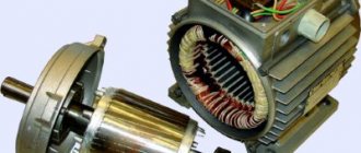
Stator in different types of electric motors
The stator is an integral component of an electric machine that remains stationary while the engine is running. The rotor is the rotating part of an electric motor that transmits mechanical energy to the output shaft. Another name for a rotor is an armature.
Synchronous or commutator motor
Electric current is transmitted to the commutator lamellas by graphite brushes. Such an electric motor will operate in both direct and alternating current networks. The pulsating magnetic field generated by the stator windings will interact with the pulsating magnetic field generated by the armature windings. The rotor will begin to rotate. Such electric motors are widely used in various household and industrial appliances: electric drills, vacuum cleaners, power drives of machine tools, and electric vehicles.
Interesting. Motors of this type have another name - synchronous. This means that the rotation speed of the rotor is equal to the rotation speed of the electromagnetic field arising in the motor.
Asynchronous motors
The overwhelming majority of electric motors used both in industry and in everyday life are asynchronous electric motors with squirrel-cage rotors. Such motors are used in three-phase and single-phase AC networks.
Asynchronous motor
The stator structure is assembled from a large number of steel plates and is located in a base housing cast from non-magnetic metals: cast iron or aluminum.
Stacked motor stator
Plate material – electrical steel. The plates are insulated from each other with a special dielectric varnish. The stator has longitudinal grooves where three windings are placed, shifted relative to the axis of rotation of the electric motor by 120 degrees from each other. The rotor is also made of insulated electrical steel plates. Rods made of aluminum, less often copper, are placed in the grooves of the rotor, connected at the ends by slip rings. Hence the name - squirrel-cage rotor. This design, called a “squirrel wheel,” plays the role of a rotor winding.
Below is a cross-sectional view of an asynchronous electric motor. You can clearly see what a stacked stator is.
Sectional view of an asynchronous motor
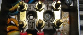
The motor windings can be connected to a three-phase electrical network in a delta or star configuration.
Three-phase motor connection options
The circuit is switched in the motor terminal box, called born or brno.
When three-phase voltage is applied, pulsating currents arise in the stator windings, which cause the appearance of a rotating magnetic field in the stator. This field crosses the conductive rods of the rotor, in which secondary pulsating currents are induced. The result is the appearance of a magnetic field in the rotor. The magnetic fields of the stator and rotor interact and cause the rods of the “squirrel wheel” to rotate, along with the rotor itself. The armature rotates at a speed slightly lower than the magnetic field of the stator.
The magnitude of this difference is called slip and can range from 2 to 8%. Due to the presence of slip, motors of this design are called asynchronous . The sliding effect is physically necessary for the operation of an asynchronous motor - there will be no lag in the rotation of the rotor from the magnetic field of the stator, no current will be induced in the rotor rods, and the magnetic field in the armature causing the rotor to rotate will disappear.
Electric motor stator
The stator of electric motors is a stationary part within which the rotor (armature) rotates on bearings.
Structurally, the stator consists of a frame and a core fixed inside it with screws. The frame is a cast or welded body made of cast iron or aluminum. The stator core of synchronous and asynchronous motors has a cylindrical shape and is formed from profiled sheets of electrical steel with a thickness of 0.35 to 0.5 mm, pre-annealed and insulated with varnish. Such plates are fastened together with longitudinal seams or staples in such a way that the profile cutouts form longitudinal grooves into which a winding consisting of a number of insulated and parallel-connected conductors is placed. This core design allows eddy currents to be weakened. The stator of a high and medium power DC motor is called an inductor and is assembled from main poles formed from sheets of electrical steel and monolithic additional poles. In low-power DC motors, the stator function is usually performed by permanent magnets.
Electric motor stator winding: main features
The relative arrangement and number of groups of stator windings of synchronous and asynchronous motors depends on their type and the required rotor speed. If only one side of a coil of one phase fits into each slot, then such a winding is called single-layer. If two coil sides belonging to different phases are placed in one groove, then the winding is called two-layer. Engines can have a different number of groups of coils, which are connected in series to each other. In three-phase synchronous and asynchronous electric motors, the stator windings are arranged in 120° increments, which allows the creation of a rotating magnetic field. Depending on the magnitude of the supply voltage, the stator windings are connected in a star or delta configuration.
In single-phase motors there are two groups of windings, shifted in space relative to each other by 90°. The phase shift is carried out thanks to capacitors installed in parallel with one of the windings.
Depending on the operating conditions, wires with different thermal insulation resistance are used to make the stator windings:
The original article is posted on our website cable.ru
.
If this material was useful to you, please share
them on social networks!
And in order not to miss the release of new articles, click “Like”
and
subscribe
to our channel:
Kabel.RF: all about electrics
.
Source
Stator material
Operating principle of the electric motor
Stator and rotor assemblies are assembled from insulated electrical steel plates with a thickness of 0.2 to 0.5 mm. This steel contains an increased amount of silicon (3-4.5%). As a result, the alloy receives increased electrical resistance and improved magnetic characteristics. The thin plate thickness and high resistivity significantly reduce parasitic Foucault eddy currents in the stator and rotor. This allows you to reduce the heating of components and parts of the electric motor and increase its electrical efficiency.
Motor rotor
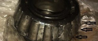
Electric motors use so-called “squirrel wheels” (squirrel-cage rotors), the design of which resembles squirrel drums.
When the stator rotates, the magnetic field moves perpendicular to the windings of the rotor conductors; current appears. This current circulates through the windings of the conductors and creates magnetic fields around each rotor conductor. Since the magnetic field in the stator is constantly changing, the field in the rotor also changes. This interaction causes the rotor to move. Like the stator, the rotor is made of electrical steel plates. But, unlike the stator, with windings made of copper wire, the rotor windings are made of cast aluminum or silumin, which act as conductors.
Read also: Why do you need flux when soldering?
Stator rewinding technology
Rotor - what is it?
Indicators of abnormal operation of the electric motor are:
- Power reduction;
- Increased heating of the case;
- “Breaking through” voltage to ground.
In this case, you should diagnose the stator malfunction. It is necessary to determine how to check the stator for an interturn short circuit with a multimeter. The winding resistance value is indicated in the reference literature for a specific motor. By checking the resistance of each winding with a multimeter, you can determine which one is defective. After which it is necessary to rewind one or all stator windings.
Basic operations:
- Removing old windings from the stator slots;
- Cleaning the grooves from the remains of old electrical and thermal insulation;
- Installation of new insulation in the stator slots;
- Laying new windings;
- Impregnation of windings with dielectric varnish and drying it;
- Checking the electrical parameters of new stator windings.
If repairs are carried out correctly, the electric motor will restore its original characteristics.
Stator device
- Frame. Must be made of non-magnetic material - cast iron or aluminum. If the engine dimensions are large, welding is used in the manufacture of the housing. Engines of this type are air-cooled. To increase heat transfer, fins are located on the surface of the housing. Bearing shields, fan casing and terminal box are also installed externally. The feet or flanges on the motor housing serve to secure it.
- Core. It is assembled from plates made of electrical steel with a thickness of about 0.5 mm. This reduces eddy currents. The core plates collected in packages are fastened with staples or seams and covered with several layers of insulating varnish. The core is secured in the frame using locking bolts.
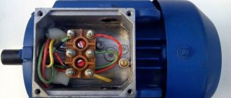
- Stator windings. Windings shifted relative to each other by 120 degrees (usually 3 pieces) are inserted into grooves on the inside of the core. They are made mainly from insulated copper and sometimes aluminum wire of round or square cross-section. The electric motor is connected to a three-phase network through a terminal box to which the ends of the windings are led out.
There are two ways to connect windings in stators:
- star, when the ends of all windings are connected at one point to connect the motor to a 380V network;
- triangle, when the windings are connected in series in a closed circuit to connect the engine to a 220V network.
It should be borne in mind that a plate is attached to the housing of each specific motor, which indicates its operating voltages. The smallest of the indicated voltages is connected with a triangle, and the highest with a star. If this rule is violated, the stator windings will burn out quite quickly, and the motor will have to be repaired.
So, knowing the structure and operating principle of the stator of an asynchronous motor and taking into account everything stated above, you will be able to make the right choice when purchasing an electric motor.
Source
Checking the commutator motor armature
Operating principle of a synchronous generator
There are two main types of faults that need to be checked at the armature of a commutator motor:
- Mechanical;
- Electrical.
On a note. Mechanical failures, as a rule, include the depletion of bearing life. There is a lot of noise when the engine is running, heating of the bearings, and longitudinal and radial play of the armature.
Electrical faults include:
- Broken wire in the winding;
- Interturn closure;
- Breakdown of the winding on the armature housing and the motor itself;
- Wear of the contact lamellas of the collector.
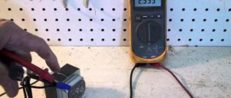
You should consider how to check the armature for an interturn short circuit. It is convenient to do this using a digital multimeter or, in its absence, a dial tester.
Electronic multimeter
How to ring an anchor? You should measure the resistance of the armature windings one by one, touching the opposite commutator lamellas with the multimeter probes. A significant deviation in the resistance value will allow you to recognize the faulty winding. Breakdown to the housing is checked with a multimeter in the resistance range of 20 kOhm. One probe is attached to the rotor shaft, the other touches the commutator lamellas in turn. The device should show the “break” state. By reading a multimeter of less than 20 kOhm, you can find out about a winding malfunction, and, therefore, the need to repair the armature.
Checking the health of the stator
Some beginners are increasingly concerned with the question of how to check whether all parts of the generator are in working order. To do this, you will need special small equipment in the form of a multimeter (popularly just a tseshka). You can use an autotester or another device that has an ohmmeter mode. As a last resort, a 12 V light bulb with wires soldered to it will do.
First you need to remove the generator from the car and disassemble it. Depending on the brand of car, there may be difficulties, since on some Lexus brand models the power source is located in a hard-to-reach place. Having reached the stator and removed it, it is necessary to clean it from dirt. Then you can proceed to the verification itself.
Electric motor repair
Repairing electric motors, such as rewinding the stator or rotor, is a responsible and painstaking operation. Certain knowledge, skills and experience are required. The easiest way to fix mechanical faults is to replace the bearings and restore the geometry of the manifold or completely replace it. It may also be necessary to change the hewn graphite brushes that supply current to the armature windings.
When repairing the electrical part of the engine, special materials, winding wire of the required brand, special tools and equipment will be required. If we are talking about repairing a limited number of electric motors, then it is better to contact a specialized repair company. This is advisable, both from the point of view of the quality of repairs and economics.
To carry out repair work in large quantities, it is necessary to create a specialized repair area, select personnel, maintain a certain amount of equipment, materials and components, and have reference literature.
Stator thermal insulation
During operation, the electric motor is subject to quite strong heating - up to 100-145 0C. To maintain operability and protect parts and assemblies from overheating, there is a fan impeller on the motor shaft that blows air over the rotor and stator. In addition, various thermal insulating materials are used to protect the stator windings, such as:
- Gaskets based on mica components and special cardboards;
- Thermal insulating materials made of fiberglass;
- Heat-resistant impregnating varnishes.
Correct technological application of such heat-insulating components ensures long-term reliable and uninterrupted operation of electric motors.
Operating principle of the electric motor
- Detailed description of the operating principle of different types of electric motors:
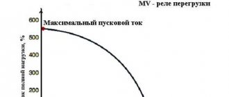
Stator protection with thermal relay
During operation, the electric motor may consume increased current from the network and experience strong heating. The reasons may be different, for example, too much load on the shaft, frequent turning on and off of the motor, increased ambient temperature. Such abnormal operating conditions can lead to overheating of the stator windings and their failure. To prevent damage to the electric motor, one or two bimetallic thermal relays are installed in the stator system - these are thermal switches called klixons.
Klixon thermal switch
When the stator temperature rises above the set value, the bimetallic klixon contact opens. The thermal switch opens the power supply circuit to the control coil of the power contactor, which supplies voltage to the electric motor. The contactor disconnects the electric motor from the power supply. Further switching on of the contactor and, therefore, the electric motor is possible only after cooling the stator windings and closing the bimetallic pair of the thermal switch.
Basic parameters of the electric motor
- Motor torque
- Motor power
- Efficiency
- Rated speed
- Rotor moment of inertia
- Rated voltage
- Electrical time constant
- Mechanical characteristics
Motor torque
Torque (synonyms: torque, torque, moment of force) is a vector physical quantity equal to the product of the radius of the vector drawn from the axis of rotation to the point of application of the force and the vector of this force.
,
- where M is torque, Nm,
- F – force, N,
- r – radius vector, m
,
- where Pnom is the rated power of the engine, W,
- nnom - rated rotation speed, min -1 [4]
Initial starting torque is the torque of the electric motor at start-up.
1 oz = 1/16 lb = 0.2780139 N (N) 1 lb = 4.448222 N (N)
torque is measured in ounce-force per inch (oz∙in) or pound-force per inch (lb∙in)
1 oz∙in = 0.007062 Nm (Nm) 1 lb∙in = 0.112985 Nm (Nm)
Motor power
Motor power is the useful mechanical power at the motor shaft.
Mechanical power
Power is a physical quantity that shows how much work a mechanism does per unit of time.
,
- where P is power, W,
- A – work, J,
- t—time, s
Work is a scalar physical quantity equal to the product of the projection of the force on the direction F and the path s traversed by the point of application of the force [2].
,
- where s – distance, m
For rotational movement
,
- where is the angle, rad,
,
- where is the angular velocity, rad/s,
In this way, you can calculate the value of mechanical power on the shaft of a rotating electric motor
Electric motor efficiency
The efficiency of an electric motor is a characteristic of the machine’s efficiency in converting electrical energy into mechanical energy.
,
- where is the efficiency of the electric motor,
- P1 — supplied power (electric), W,
- P2 - useful power (mechanical), W
- Wherein losses in electric motors
- electrical losses - in the form of heat as a result of heating current-carrying conductors;
- magnetic losses - losses due to magnetization reversal of the core: losses due to eddy currents, hysteresis and magnetic aftereffects;
- mechanical losses - friction losses in bearings, ventilation, brushes (if any);
- additional losses - losses caused by higher harmonics of magnetic fields arising due to the gear structure of the stator, rotor and the presence of higher harmonics of the magnetomotive force of the windings.
due to:
Electric motor efficiency can vary from 10 to 99% depending on the type and design.
The International Electrotechnical Commission defines the efficiency requirements for electric motors. According to the IEC 60034-31:2010 standard, four efficiency classes are defined for synchronous and asynchronous motors: IE1, IE2, IE3 and IE4.
Rotation frequency
- where n is the rotation speed of the electric motor, rpm
Rotor moment of inertia
The moment of inertia is a scalar physical quantity, which is a measure of the inertia of a body in rotational motion around an axis, equal to the sum of the products of the masses of material points by the squares of their distances from the axis
,
- where J is the moment of inertia, kg∙m 2,
- m—mass, kg
1 oz∙in∙s 2 = 0.007062 kg∙m 2 (kg∙m 2)
The moment of inertia is related to the moment of force by the following relation
,
- where is angular acceleration, s -2 [2]
,
Rated voltage
Rated voltage is the voltage for which the network or equipment is designed and to which their operating characteristics are related [3].
Electrical time constant
The electrical time constant is the time, counted from the moment a direct voltage is applied to the electric motor, during which the current reaches a level of 63.21% (1-1/e) of its final value.
,
- where is the time constant, s
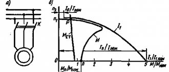
Mechanical characteristics
The mechanical characteristic of the engine is a graphically expressed dependence of the shaft speed on the electromagnetic torque at a constant supply voltage.
Motors used in industry
Both types of motors are successfully used in industry: asynchronous with a squirrel-cage rotor, and synchronous commutator.
The first type of device has important advantages:
- Low price;
- Reliability and durability;
- Easy to use.
There are also disadvantages:
- Impossibility of smooth control of armature speed;
- Low rotation speed - limit 3000 rpm. in networks with a frequency of 50Hz;
- Large starting currents.
However, the advantages of these products far outweigh their disadvantages.
For your information. Asynchronous motors are used in those devices that require constant operating modes of industrial or transport equipment. For example, in drives of various pumps, belt conveyors, in ventilation systems, in lifting mechanisms. The niche of asynchronous electric machines occupies 65-75% of the total volume of electric motors used.
Synchronous commutator motors have their advantages:
- Possibility of smooth, stepless change of rotation speed;
- Great power;
- High rotation speed.
Disadvantages inherent in commutator electric motors:
- Relatively high cost;
- Sliding contacts of the armature commutator, reducing operational reliability and reducing the service life of the machine;
- Frequent maintenance required.
They are used where a smooth change in angular speeds is necessary: these are machine tool drives, traction motors of electric vehicles, and precision installation systems.
Both types of engines are widely used in industry and everyday life. For their long-term and trouble-free operation, it is necessary to carry out routine maintenance, and, if necessary, restoration repairs, including rewinding the stator and rotor windings.
Let's connect the stator and rotor. What will happen?
Thus, we have an asynchronous squirrel-cage motor with a rotor in the winding of which electric current passes. This will be the cause of the appearance of a magnetic field around the armature winding. However, the polarity of this flux will be different from that created by the stator. Accordingly, the force generated by it will counteract the one caused by the magnetic field of the primary winding. This will set the rotor in motion, since the secondary coil is assembled on it, and the armature shaft shanks are fixed in the motor housing on bearings.
Read also: Light sensor for turning on the light
Let us consider the situation of interaction of forces arising from the magnetic fields of the stator and rotor over time. We know that the magnetic field of the primary winding rotates and has a certain frequency. The force it creates will move at a similar speed. This will make the asynchronous motor work. And its rotor will rotate freely around its axis.