Introduction
If someone came up with the idea of conducting a survey of the world's population on the topic “What do you know about inductance?”, the overwhelming number of respondents would simply shrug their shoulders. But this is the second most numerous technical element, after transistors, on which modern civilization is based! Detective fans, remembering that in their youth they read Sir Arthur Conan Doyle’s exciting stories about the adventures of the famous detective Sherlock Holmes, will, with varying degrees of confidence, mutter something about the method that the above-mentioned detective used. At the same time, implying the method of deduction, which, along with the method of induction, is the main method of knowledge in Western philosophy of the New Age.
With the induction method, individual facts, principles are studied and general theoretical concepts are formed based on the results obtained (from particular to general). The deduction method, on the contrary, involves research from general principles and laws, when the provisions of the theory are distributed into individual phenomena.
It should be noted that induction, in the sense of method, does not have any direct relation to inductance, they simply have a common Latin root inductio
- guidance, motivation - and mean completely different concepts.
Only a small part of those surveyed from among the exact sciences - professional physicists, electrical engineers, radio engineers and students in these fields - will be able to give a clear answer to this question, and some of them are ready to give an entire lecture on this topic right away.
Definition of inductance
In physics, inductance, or the coefficient of self-induction, is defined as the coefficient of proportionality L between the magnetic flux Ф around a current-carrying conductor and the current I generating it, or - in a more strict formulation - this is the coefficient of proportionality between the electric current flowing in any closed circuit and the magnetic flux created by this current:
or
To understand the physical role of the inductor in electrical circuits, one can use the analogy of the formula for the energy stored in it when current I flows with the formula for the mechanical kinetic energy of the body.
For a given current I, inductance L determines the energy of the magnetic field W created by this current I:
Similarly, the mechanical kinetic energy of a body is determined by the mass of the body m and its speed V:
That is, inductance, like mass, does not allow the energy of the magnetic field to instantly increase, just as mass does not allow this to happen with the kinetic energy of the body.
Let's study the behavior of current in inductance:
Rice. 1. Electrical diagram of the experiment
Rice. 2. Physical implementation of the experiment
Rice. 3. Oscillogram of current through inductance. The yellow oscillogram is the output of the signal generator, the blue one is the signal at the resistor.
Due to the inertia of the inductance, the fronts of the input voltage are delayed. In automation and radio engineering, such a circuit is called an integrating circuit, and is used to perform the mathematical operation of integration.
Let's study the voltage on the inductor:
Rice. 4. Electrical diagram of the experiment
Rice. 6. Voltage oscillogram across the inductance (blue)
At the moments of applying and removing voltage, due to the self-inductive emf inherent in the inductance coils, voltage surges occur. Such a circuit in automation and radio engineering is called differentiating, and is used in automation to correct processes in a controlled object that are fast in nature.
Rice. 5. By and large, in all electric current generators of any type, as well as in electric motors, their windings are inductor coils.
How to find voltage through induction
Inductors and calculations
Inductors, unlike conductors, do not have stable resistance. However, for them there is a certain mathematical relationship between voltage and current:
As you can see, this formula is similar to the analogous formula of Ohm's Law for a capacitor. It relates one variable (in our case, the voltage across the inductor) to the rate of change of another variable (the current through the inductor). Both the voltage (u) and the rate of change of current here (di/dt) are instantaneous: they are taken at a certain point in time. The rate of change of current (di/dt) is expressed in amperes per second, and has a positive value when the current increases, and a negative value when it decreases.
The behavior of an inductor (similar to a capacitor) is closely related to the time variable. If we do not take into account the internal resistance of the inductor (for the sake of the purity of the experiment, we take it equal to zero), then the voltage at its terminals will depend on the change in current over time.
Let's assume that we connect an ideal inductor (having zero wire resistance) to a circuit that allows us to measure the current through that coil using a potentiometer:
If the potentiometer mechanism is in one position (the slider is stationary), then an ammeter connected in series with it will register a constant (constant) current, and a voltmeter connected to the inductor will show 0 volts. Since the current in this case is constant, the rate of change (di/dt) will be zero. Looking carefully at the above equation, we can conclude that at a zero du/dt value, the instantaneous voltage on the coil will also be zero. From the point of view of physics, if the current is constant (unchanged), then the magnetic field produced by the inductor will also be constant. If there is no change in magnetic flux (dΦ/dt = 0 Weber per second), the induced voltage will be zero.
If the potentiometer slider is slowly moved up, its resistance will slowly decrease. The current in the circuit will increase, which can be seen by the slow deflection of the ammeter needle:
If the potentiometer slider is moved at a constant speed, then the current in the circuit will increase evenly, which means the di/dt ratio will have a fixed value. This value, multiplied by the inductance (also having a fixed value), will give us a constant voltage of some magnitude. From a physics point of view, a gradual increase in current will lead to an increase in the magnetic field. The increasing magnetic flux of the field will create an induced voltage in the coil, expressed by Faraday's equation: e = N(dΦ/dt). This voltage takes on a polarity that tries to counteract the change in current. In other words, the polarity of the voltage induced as a result of an increase in current will be oriented against the direction of that current in order to maintain its magnitude at the same level. This phenomenon demonstrates a more general principle of physics known as Lenz's Rule, which states: An induced current is always in such a direction that it weakens the action of the cause that excites the current.
General information
In order to understand what the inductance of the coil depends on, it is necessary to study in detail all the information about this physical quantity. The first step is to consider the accepted international designation of the parameter, its purpose, characteristics and units of measurement.
The first letter of the surname of another famous physicist, Emilia Lenza, was taken as a designation for inductance in formulas and when carrying out calculations. Today, the symbol L continues to be used when referring to this parameter.
The outstanding American physicist Joseph Henry was the first to discover the phenomenon of inductance. In his honor, physicists named the unit of measurement in the international SI, which is most often used in calculations. In other systems (Gaussian and SGS), inductance is measured in centimeters. To simplify the calculations, a relationship was adopted in which 1 cm equals 1 nanohenry. The very rarely used SGSE system leaves the self-induction coefficient without any units of measurement or uses the stathenry value. It depends on several parameters and is approximately equal to 89875520000 henry.
Among the main properties of inductance are:
- The parameter value can never be less than zero.
- The indicator depends only on the magnetic properties of the coil core, as well as on the geometric dimensions of the circuit.
Solenoid inductance
Solenoid-shaped coil (finite length).
A solenoid is a long, thin coil, that is, a coil whose length is much greater than its diameter (also in further calculations here it is implied that the thickness of the winding is much less than the diameter of the coil). Under these conditions and without the use of magnetic material, the magnetic flux density (or magnetic induction) B{\displaystyle B}, which is expressed in SI units of tesla, inside the coil is effectively constant and is (approximately) equal to
B=μNil{\displaystyle \displaystyle B=\mu _{0}Ni/l}
or
B=μni,{\displaystyle \displaystyle B=\mu _{0}ni,}
where μ{\displaystyle \mu _{0}} is the magnetic constant, N{\displaystyle N} is the number of turns, i{\displaystyle i} is the current written in amperes, l{\displaystyle l} is the length of the coil in meters and n{\displaystyle n} is the winding density of turns in . Neglecting edge effects at the ends of the solenoid, the flux linkage through the coil is equal to the flux density B{\displaystyle B} multiplied by the cross-sectional area S{\displaystyle S} and the number of turns N{\displaystyle N}:
Ψ=μN2iSl=μn2iV,{\displaystyle \displaystyle \Psi =\mu _{0}N^{2}iS/l=\mu _{0}n^{2}iV,}
where V=Sl{\displaystyle V=Sl} is the volume of the coil. From this follows the formula for the inductance of the solenoid (without a core):
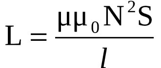
L=μN2Sl=μn2V.{\displaystyle \displaystyle L=\mu _{0}N^{2}S/l=\mu _{0}n^{2}V.}
If the coil inside is completely filled with magnetic material (core), then the inductance differs by a factor μ{\displaystyle \mu } - the relative magnetic permeability of the core:
L=μμN2Sl=μμn2V.{\displaystyle \displaystyle L=\mu _{0}\mu N^{2}S/l=\mu _{0}\mu n^{2}V.}
In the case when μ>>1{\displaystyle \mu >>1}, one can (should) under S
understand the cross-sectional area of the core and use this formula even with thick winding, unless the total cross-sectional area of the coil exceeds the cross-sectional area of the core many times.
Calculation of the inductor
Online calculation of a multilayer coil. The calculator calculates using an algorithm using Maxwell's elliptic integrals. An inductor is a helical, helical or helical coil made of a coiled insulated conductor, which has significant inductance with a relatively small capacitance and low active resistance. The inductance of the coil depends on its geometric dimensions, the number of turns and the method of winding the coil. The larger the diameter, winding length and number of turns of the coil, the greater its inductance.
see also
A very strange result is obtained. At 3.4 mg d20 L35 wire 1/1.2, one layer is obtained and the wire consumption is less than one meter. Like this??
Try changing microhenry to millihenry
Maybe they confused milihenry and microhenry?
Here the calculation is clearly without a core, otherwise there would be other data, for example, the permeability of the core.
What about the core? With or without a core?
Ingvar, why do you really need the letters NNNN? Length! I give it.
The winding length is the length of the coil from the starting point of the winding to the end of the calculated conductor (meters), the length of the conductor is calculated from the resistance you need. For example, for a magnetic system you need at least 1 mm and no more than 3 (2 layers of winding), but due to the length of the conductor you get 6 mm, you will have to increase the number of layers (up to 4) and make the coil thicker, but shorter.
The main thing is inductance and resistance. The longer the wire, the greater its resistance!
The length of the winding does not affect the results in any way. Is this how it should be?
Source
Single turn circuit and coil
The inductance of a loop representing a turn of wire depends on the amount of current flowing and the magnetic flux passing through the loop. For the inductance of the circuit, the formula determines the parameter, respectively, through the flux and current strength:
The weakening of the magnetic flux due to the diamagnetic properties of the environment reduces the inductance.
We advise you to study Active antenna for car
The parameter for a multi-turn coil is proportional to the square of the number of turns, since not only the magnetic flux from each turn increases, but also the flux linkage:
In order to calculate the inductance of a coil, the formula must take into account not only the number of turns, but also the type of winding and geometric dimensions.
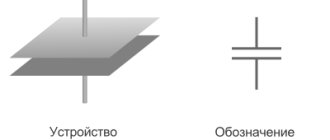
Inductance and capacitor
The current-carrying elements of the device are capable of creating its own inductance. These are such structural parts as masonry, connecting busbars, down conductors, terminals and fuses. It is possible to create additional capacitor inductance by connecting busbars. The operating mode of an electrical circuit depends on inductance, capacitance and active resistance. The formula for calculating the inductance that occurs when approaching the resonant frequency is as follows:
Ce = C: (1 - 4Π2f2LC),
where Ce determines the effective capacitance of the capacitor, C indicates the actual capacitance, f is the frequency, L is the inductance.
The inductance value must always be taken into account when working with power capacitors. For pulse capacitors, the most important value is the self-inductance. Their discharge falls on the inductive circuit and has two types - aperiodic and oscillatory.
The inductance in a capacitor depends on the connection diagram of the elements in it. For example, when sections and buses are connected in parallel, this value is equal to the sum of the inductances of the package of main buses and terminals. To find this kind of inductance, the formula is as follows:
Lk = Lp + Lm + Lb,
where Lk shows the inductance of the device, Lp of the package, Lm of the main buses, and Lb of the inductance of the terminals.
If, in a parallel connection, the bus current varies along its length, then the equivalent inductance is determined as follows:
Lk = Lc : n + µ0 l x d : (3b) + Lb,
where l is the length of the tires, b is its width, and d is the distance between the tires.
Inductance meter for multimeter
Despite the fact that it is rare to determine inductance when working with electronics, it is still sometimes necessary, and multimeters that measure inductance are quite difficult to find. In this situation, a special attachment to a multimeter will help, allowing you to measure inductance.
Often, for such a set-top box, a digital multimeter is used that is set to measure voltage with a measurement accuracy threshold of 200 mV, which can be purchased ready-made at any electrical and radio equipment store. This will allow you to make a simple attachment for a digital multimeter.
Solenoid inductance
Solenoid-shaped coil (finite length).
A solenoid is a coil whose length is much greater than its diameter (also in further calculations it is assumed that the thickness of the winding is much less than the diameter of the coil). Under these conditions and without the use of a magnetic core, the magnetic flux density (or magnetic induction) B{\displaystyle B}, which is expressed in SI units of tesla, inside the coil away from its ends is (approximately) equal to
B=μNil{\displaystyle \displaystyle B=\mu _{0}Ni/l}
or
B=μni,{\displaystyle \displaystyle B=\mu _{0}ni,}
where μ{\displaystyle \mu _{0}} is the magnetic constant, N{\displaystyle N} is the number of turns, i{\displaystyle i} is the current in amperes, l{\displaystyle l} is the length of the coil in meters and n {\displaystyle n} - winding density of turns in . Neglecting edge effects at the ends of the solenoid, the flux linkage through the coil is equal to the flux density B{\displaystyle B} multiplied by the cross-sectional area S{\displaystyle S} and the number of turns N{\displaystyle N}:
Ψ=μN2iSl=μn2iV,{\displaystyle \displaystyle \Psi =\mu _{0}N^{2}iS/l=\mu _{0}n^{2}iV,}
where V=Sl{\displaystyle V=Sl} is the volume of the coil. From this follows the formula for the inductance of the solenoid (without a core):
L=μN2Sl=μn2V.{\displaystyle \displaystyle L=\mu _{0}N^{2}S/l=\mu _{0}n^{2}V.}
If the coil inside is completely filled with a magnetic core, then the inductance differs by a factor μ{\displaystyle \mu } - the relative magnetic permeability of the core:
L=μμN2Sl=μμn2V.{\displaystyle \displaystyle L=\mu _{0}\mu N^{2}S/l=\mu _{0}\mu n^{2}V.}
In the case when μ>>1{\displaystyle \mu >>1}, under S
You can understand the cross-sectional area of the core and use this formula even with thick winding, unless the total cross-sectional area of the coil exceeds the cross-sectional area of the core many times.
Carrying out inductance measurements
After assembly, the multimeter attachment must be tested. There are several ways to check your device:
- Determination of the inductance of the measuring attachment. To do this, you need to short-circuit two wires intended for connection to the inductive coil. For example, with a length of each wire and jumper of 3 cm, one turn of the induction coil is formed. This turn has an inductance of 0.1 - 0.2 μH. When determining inductance above 5 μH, this error is not taken into account in the calculations. In the range of 0.5 - 5 µH, when measuring, it is necessary to take into account the inductance of the device. Readings less than 0.5 µH are approximate.
- Measuring an unknown inductance value. Knowing the frequency of the coil, using a simplified formula for calculating inductance, you can determine this value.
- In the case when the response threshold of silicon pn junctions is higher than the amplitude of the measured electrical circuit (from 70 to 80 mV), it is possible to measure the inductance of the coils directly in the circuit itself (after de-energizing it). Since the set-top box’s own capacitance is of great importance (25330 pF), the error in such measurements will be no more than 5%, provided that the capacitance of the measured circuit does not exceed 1200 pF.
When connecting the set-top box directly to the coils located on the board, 30 centimeters long wiring with clamps for fixation or probes is used. The wires are twisted at the rate of one turn per centimeter of length. In this case, the inductance of the set-top box is formed in the range of 0.5 - 0.6 μH, which also must be taken into account when measuring inductance.
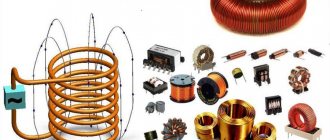
Application of coils in technology
The phenomenon of electromagnetic induction has been known for a long time and is widely used in technology. Examples of using:
- smoothing out ripples and interference, storing energy;
- creation of magnetic fields in various devices;
- feedback circuit filters;
- creation of oscillatory circuits;
- transformers (a device of two coils connected inductively);
- power electrical engineering uses to limit the current during a short circuit. on power lines (inductors called reactors);
- limiting the current in welding machines - inductance coils make its operation more stable, reducing the arc, which allows you to get an even welding seam that has the greatest strength;
- the use of coils as electromagnets of various actuators;
- electromagnetic relay windings;
- induction furnaces;
- establishing the quality of iron ores, studying rocks by determining the magnetic permeability of minerals.
What is an inductor
This element is also called a choke. This is an insulated wire rolled into a spiral. Such a spiral is characterized by large inductive and small capacitive parameters.
Important! The inductor prevents the flow of alternating current because it has significant inertia. It prevents any change in the current passing through the turns. It makes no difference whether it increases or decreases.
In this regard, these elements are used in electrical engineering to implement:
- current limiting;
- weakening of beats;
- interference suppression;
- magnetic field formation;
- manufacturing motion sensors.
The choke is part of the oscillatory circuit system in resonance circuits and is used in delay lines.
Self-inductance and inductance measurement
Inductance is a quantity that is equal to the ratio of the magnetic flux passing through all turns of the circuit to the current strength:
L = N x F: I.
The inductance of the circuit depends on the shape, size of the circuit and the magnetic properties of the environment in which it is located. If an electric current flows in a closed circuit, a changing magnetic field arises. This will subsequently lead to the occurrence of EMF. The birth of an induction current in a closed circuit is called “self-induction”. According to Lenz's rule, the value does not allow the current in the circuit to change. If self-induction is detected, then an electrical circuit can be used in which a resistor and a coil with an iron core are connected in parallel. Electric lamps are also connected in series with them. In this case, the resistance of the resistor is equal to the DC resistance of the coil. The result will be bright burning lamps. The phenomenon of self-induction occupies one of the main places in radio engineering and electrical engineering.
Setting up an inductance meter
In order to calibrate the attachment for measuring inductance, you will need several induction coils with known inductance (for example, 100 μH and 15 μH).
The coils are connected one by one to the attachment and, depending on the inductance, the trimmer resistor slider on the multimeter screen sets the value 100.0 for a 100 µH coil and 15 for a 15 µH coil with an accuracy of 5%.
Using the same method, the device is configured in other ranges. An important factor is that accurate test inductor values are required to accurately calibrate the attachment.
An alternative method for determining inductance is the LIMP program. But this method requires some preparation and understanding of how the program works.
But in both the first and second cases, the accuracy of such inductance measurements will not be very high. This inductance meter is not suitable for working with high-precision equipment, but for home use or for radio amateurs it will be an excellent assistant.
Inductive reactance - how to find it
A real coil has not only reactive, but also ordinary resistance. Inductive reactance is determined by the formula:
XL=2*P*v*L
The following notations are used here:
- XL is the value under consideration.
- The symbol “P” represents the number Pi.
- V represents frequency.
- L is a designation for the amount of inductance.
It should be noted that the value (2*P*v) represents a circular frequency, which is denoted by the Greek symbol “omega”.
Coils with different cores
The quantity under consideration obeys Ohm's law. The formula looks like this:
I=U/XL
I, U represent current and voltage, XL is inductive reactance.
Coil magnetic field configuration
To determine the required value, you can use the given formulas. You can use an ammeter and a voltmeter. The first of them must be connected in series, the second in parallel.
The following must be taken into account. In fact, in a circuit in which inductance is connected, there are two types of resistance: active and reactive. By measuring current and voltage, you can determine their resulting value. It must be remembered that it is not their simple sum.
The fact is that in an alternating circuit, where there is only a coil and no capacitor, the voltage is ahead of the current by a quarter of the oscillation period. This value is equal to 90 degrees.
The impedance is determined as follows. To do this, you need to draw a corresponding diagram. If you plot the normal value horizontally, and the reactive value vertically, and then build a rectangle using these vectors, then the length of its diagonal will be equal to the full value.
Magnetic field of a wire
For example, if you select the elements of the circuit in such a way that both of these values are equal in absolute value, then the required part will be determined as their total value multiplied by the square root of two.
In order to obtain information about the dependence of inductive reactance on frequency, you can use an oscilloscope.
When using alternating current, it is necessary to take into account not only ordinary, but also inductive reactance. It occurs if there is a coil in the electrical circuit.
We advise you to study All about fuses
Series connection of inductors.
When inductors are connected in series, they can be replaced by one coil with an inductance value equal to:
L_0 = L_1 + L_2
It seems that everything is simple, it couldn’t be simpler, but there is one important point. This formula is valid only if the coils are located at such a distance from each other that the magnetic field of one coil does not intersect the turns of the other:
If the coils are located close to each other and part of the magnetic field of one coil penetrates the second, then the situation is completely different. There are two options:
- the magnetic fluxes of the coils have the same direction
- magnetic fluxes are directed towards each other
The first case is called consonant connection of coils - the beginning of the second coil is connected to the end of the first. And the second option is called counter-connection - the end of the second coil is connected to the beginning of the first. In the diagrams, the beginning of the coil is indicated by the symbol “*“. Thus, in the diagram shown in the figure we have a consistent connection of the inductors. For this case, the total inductance is determined as follows:
L = L_1 + L_2 + 2M
Where M is the mutual inductance of the coils. When connecting inductors connected in series in opposite directions:
L = L_1 + L_2\medspace-\medspace 2M
It can be noted that if the fluxes have the same direction (consonant inclusion), then the total inductance increases by double the mutual inductance. And if the flows are directed towards each other, it decreases by the same amount.
Inductance, its unit is si. Inductance of a long solenoid.
Inductance
(or
coefficient of self-induction
) - a coefficient of proportionality between the electric current flowing in any closed circuit and the magnetic flux created by this current through the surface, the edge of which is this circuit. .
— magnetic flux, — current in the circuit, — inductance.
They often talk about the inductance of a straight long wire (see). In this case and other cases (especially in those that do not correspond to the quasi-stationary approximation) when a closed loop is not easy to adequately and unambiguously indicate, the above definition requires special clarification; The approach (mentioned below) that relates inductance to magnetic field energy is partly useful for this.
Inductance is used to express the self-inductive emf in a circuit that occurs when the current in it changes:
.
From this formula it follows that the inductance is numerically equal to the self-inductive emf that occurs in the circuit when the current changes by 1 A in 1 s.
For a given current strength, inductance determines the energy of the magnetic field created by this current:
.
How to find the inductance of a conductor
Electric current creates its own magnetic field. The magnetic flux through the circuit is proportional to the magnetic field induction (F
B), induction is proportional to the current in the conductor (B
I), therefore the magnetic flux is proportional to the current strength (F
The self-induction emf depends on the rate of change of current in the electrical circuit, on the properties of the conductor (size and shape) and on the relative magnetic permeability of the medium in which the conductor is located.
A physical quantity showing the dependence of the self-induction emf on the size and shape of the conductor and on the environment in which the conductor is located is called the self-induction coefficient or inductance.
Inductance – physical. a value numerically equal to the self-inductive emf that occurs in the circuit when the current changes by 1 Ampere in 1 second.
Inductance can also be calculated using the formula:
where Ф is the magnetic flux through the circuit, I is the current strength in the circuit.
SI units of inductance:
The inductance of the coil depends on: the number of turns, the size and shape of the coil and the relative magnetic permeability of the medium
Mutual inductance is a quantity characterizing the magnetic coupling of two or more electrical circuits (circuits). If there are two conducting circuits, then part of the magnetic induction lines created by the current in the first circuit will penetrate the area limited by the second circuit (i.e., it will be linked to circuit 2).
Magnetic flux Ф12 through circuit 2, created by current I1 in circuit 1, is directly proportional to the current:
The proportionality coefficient M12 depends on the size and shape of circuits 1 and 2, the distance between them, their relative position, as well as the magnetic permeability of the environment and is called mutual inductance or the coefficient of mutual induction of circuits 1 and 2. In the SI system I.V. measured in Henry.
Transformer EMF. The operating principle of the transformer is based on the phenomenon of electromagnetic induction. The induction lines of the magnetic field created by alternating current in the primary winding, thanks to the presence of the core, penetrate the turns of the secondary winding with virtually no losses. Since the magnetic flux in the secondary winding changes with time (since there is alternating current in the primary winding), according to Faraday’s law, an induced emf is excited in it. The transformer can only operate on alternating current, because the magnetic flux created by direct current does not change over time.
Oscillatory circuit
A capacitance and an inductive element connected in a circuit form an oscillatory circuit with pronounced frequency properties and will be a resonant system. The system uses a capacitor, changing the capacitance of which, you can correct the frequency properties.
If you measure the resonant frequency using a known capacitor, you can determine the inductance of the coil.
Inductance is an important element in various fields of electrical engineering. For proper use, you need to know all the parameters of the elements used.
A device that allows you to determine the parameters of inductors, including quality factor, may be called an L-meter or Q-meter.
Calculation of the inductor
When building electronic devices, you often have to deal with an inductive circuit element. When only the inductance value L is indicated in the drawing, you have to calculate the inductor yourself. There are many programs on the Internet that allow you to calculate the inductance of coils online using a special calculator. Knowing how the element is structured, you can manually perform all the calculations.
How to recalculate inductors (single-layer, cylindrical)
The need to recalculate the inductors arises when the required wire diameter specified in the design description is not available and it is replaced with a wire of a different diameter; when changing the diameter of the coil frame.
If there is no wire of the required diameter, which is the most common reason for recalculating coils, you can use a wire of a different diameter.
A change in the diameter of the wire up to 25% in one direction or another is quite acceptable and in most designs does not affect the quality of their work. Moreover, increasing the diameter of the wire is permissible in all cases, since it reduces the ohmic resistance of the coil and increases its quality factor.
Reducing the diameter worsens the quality factor and increases the current density per unit cross-section of the wire, which cannot be more than a certain permissible value.
The number of turns of a single-layer cylindrical coil is recalculated when replacing a wire of one diameter with another using the formula:
Where:
- n is the new number of coil turns;
- n1 - number of coil turns specified in the description;
- d—diameter of the existing wire;
- d1 - wire diameter specified in the description.
As an example, let us recalculate the number of turns of the coil shown in Fig. 1, for wire with a diameter of 0.8 mm:
(winding length l= 18 X 0.8 = 14.4 mm, or 1.44 cm).
Thus, the number of turns and winding length have decreased slightly. To check the correctness of the recalculation, it is recommended to perform a new calculation of the coil with a changed wire diameter:
When recalculating a coil due to a change in its diameter, one should use the percentage relationship between the diameter and the number of turns of the coil.
This relationship is as follows: when the diameter of the coil increases by a certain number of percent, the number of turns decreases by the same percentage, and, conversely, when the diameter decreases, the number of turns increases by an equal number of percent. To simplify calculations, you can take the diameter of the frame as the diameter of the coil.
Rice. 2. Inductors. Example.
So, for example, let's recalculate the number of turns of a coil (Fig. 2, a), which has a diameter of 1.5 cm, to a diameter equal to 1.8 cm (Fig. 2, b). According to the conversion conditions, the diameter of the frame increases by 3 mm, or 20%.
Consequently, to maintain a constant value of the inductance of this coil when winding it on a frame of larger diameter, it is necessary to reduce the number of turns by 20%, or by 8 turns. Thus, the new coil will have 32 turns.
Let's check the recalculation and determine the error made as a result of the recalculation. The coil (see Fig. 2, a) has the inductance:
New reel on a frame with an increased diameter:
The error in recalculation is 0.25 μH, which is quite acceptable for calculations in amateur radio practice.
Inductors
V. POLYAKOV, Moscow
Any conductor carrying current creates a magnetic field around itself. The ratio of the magnetic flux of this field to the current generating it is called inductance. The inductance of a straight piece of conductor is small and amounts to 1...2 µH per meter of length, depending on the diameter of the wire (thin conductors have a higher inductance). More accurate results are given by the formula L = 0.2ℓ(ln4ℓ/d - 1), where ℓ is the length of the wire; d is its diameter. Both sizes must be taken in meters (under the logarithm sign it is permissible in any, but identical units), the inductance will be in microhenry. To make calculations easier, recall that the natural logarithm of any number is 2.3 times greater than the decimal logarithm (which can be found using tables, a slide rule or a calculator), i.e. lnx = 2.3lgx. Why did we give this formula? Let's explain with an example. Let the leads of a certain radio element have a length of 4 cm and a diameter of 0.4 mm. Let's count their inductance. 2.3lg100 = 4.6 and 0.2∙0.04∙3.6 = 0.03 (rounded). So, the inductance of each pin is close to 0.03 μH, and the inductance of two pins is 0.06 μH. With a capacitance of only 4.5 pF (and the mounting capacitance can be higher), such an inductance forms an oscillatory circuit tuned to a frequency of 300 MHz - remember Thomson’s formula: f = 1/2π√LC. This is why installation on VHF cannot be done with long wires and long leads of parts should not be left. To increase the inductance, the conductor is rolled into a ring. The magnetic flux inside the ring increases, and the inductance becomes approximately three times greater: L = 0.2πD(ln8D/d - 2). Here D is the diameter of the ring, the dimensions are the same. A further increase in inductance occurs with an increase in the number of turns, while the magnetic fluxes of individual turns not only add up, but also affect all other turns. Therefore, inductance increases in proportion to the square of the number of turns. If there are N turns in the coil, the inductance obtained for one turn must be multiplied by N². For a single-layer cylindrical coil with a length ℓ much greater than the diameter D ( Fig. 23 ), the inductance is calculated quite accurately using the formula L = μμₒN²S/ℓ, strictly derived for a very long solenoid or torus. All dimensions here are in the SI system (meters, Henry), μₒ = 4π∙10⁻⁷ H/m - magnetic constant; S = πD²/4 – cross-sectional area of the coil; μ is the effective magnetic permeability of the magnetic circuit. For open magnetic cores, it is significantly less than the permeability of the material itself. For example, for a magnetic antenna rod made of ferrite grade 600NN (magnetic permeability 600), μ barely reaches 150. If there is no magnetic circuit, μ = 1.
This formula gives very accurate results for toroidal coils, and ℓ corresponds to the circumference of the annular magnetic circuit, measured along its center line. The formula is also suitable for low-frequency transformers wound on an W-shaped magnetic core ( Fig. 24 ). In this case, S = ab is the cross-sectional area of the magnetic circuit, and ℓ is the average length of the magnetic field line, shown in the dotted line in the figure. For closed magnetic cores assembled without a gap, as for ferrite rings, μ is taken equal to the magnetic permeability of the material. A small gap slightly reduces μ. Its influence can be taken into account by increasing the length of the magnetic field line ℓ by the value δμ, where δ is the gap width, μ is the magnetic permeability of the core material. As you can see, inductance practically does not depend on the diameter of the wire. For low-frequency coils, the wire diameter is selected based on the permissible current density, for copper conductors 2...3 amperes for each mm² of conductor cross-section. In other cases, especially with RF coils, one strives to obtain a minimum conductor resistance in order to increase the quality factor (the ratio of inductive to active reactance).
For this purpose, it would seem that it is necessary to increase the diameter of the wire, but then the length of the winding increases, which reduces the inductance, and with a close, multi-layer arrangement of turns, the effect of “displacing” the current from the winding is observed, which increases the resistance. The effect is similar to current displacement at high frequencies in any conductor, resulting in current flowing only in a thin skin layer near the surface of the conductor. The skin layer thickness decreases, and the wire resistance increases in proportion to the square root of the frequency. Thus, to obtain the required inductance and quality factor, it is not at all necessary to choose the thickest wire. For example, if a single-layer coil (see Fig. 23) is wound with thick wire turn to turn or with twice as thin wire, but with a step equal to the diameter of the wire, the inductance will remain the same and the quality factor will hardly decrease. The quality factor increases as all dimensions of the coil increase along with the diameter of the wire, mainly its diameter. To obtain maximum quality factor and inductance, it is more advantageous to make the coil short but large in diameter, with a D/ℓ ratio of about 2.5. The inductance of such coils is more accurately calculated using the empirical (selected by experience) formula L = 0.1D²N²/(4D + 11ℓ). where the dimensions are taken in centimeters, and the inductance is obtained in microhenry. It is curious that the same formula is applicable for a spiral or basket flat coil ( Fig. 25 ).
The average diameter is taken as D: D = (Dmax + Dmin)/2, and as ℓ - the winding width, ℓ = (Dmax - Dmin)/2. The inductance of a multilayer coil without a core ( Fig. 26 ) is calculated by the formula L = 0.08D²N²/(3D + 9b + 10c), where the dimensions are substituted in centimeters, and the inductance is obtained in microhenry. With dense ordinary winding, the quality factor does not exceed 30...50, “loose” winding (in bulk, universal) gives high quality factor values. Even better is the “cellular” winding, now almost forgotten. At frequencies up to 10 MHz, the quality factor increases when using Litz wire - a wire twisted from many thin insulated strands. Litz wire has a larger total wire surface, through which current actually flows due to the skin effect, and therefore has less resistance at high frequencies.
A magnetodielectric trimmer increases the inductance up to 2-3 times, depending on the size of the trimmer. An even greater increase in inductance is provided by closed or partially closed magnetic circuits, for example, pot-shaped ones. In this case, it is better to use the strict formula for a solenoid or torus (see above). The quality factor of a coil on a closed magnetic circuit is determined not so much by the wire as by losses in the core material. To conclude the chapter, we present several useful formulas for calculating the active resistance of wires. The linear resistance (per meter of length) of a copper wire at direct current and low frequencies (Ohm/m) can be easily found using the formula R = 0.0223/d², where d is the diameter of the wire, mm. The thickness of the skin layer for copper (mm) is approximately equal to 1/15√f (MHz). Please note: already at a frequency of 1 MHz, the current penetrates the wire to a depth of only 0.07 mm! In the case where the wire diameter is greater than the skin layer thickness, the resistance increases compared to the resistance at direct current. The linear resistance of the wire at high frequency is estimated using the formula R = √f/12d (mm). Unfortunately, these formulas cannot be used to determine the active resistance of coils, since due to the effect of the proximity of the turns, it turns out to be even greater. It's time to give answers to the first problems given in the previous sections. Problem from the introduction (“Radio”, 2002, No. 9, p. 52): what is the duration of single pulses (relative to the period) at the output of a logic element (Fig. 2), if it switches at a voltage of 2 V, and the input is sinusoidal signal with an amplitude of 4 V? It is easier and more visual to solve this problem graphically - you need to draw a sinusoid with an amplitude of 4 V as accurately as possible and draw a straight horizontal line at the level of the switching threshold of the element, i.e. 2 V ( Fig. 27 ).
The element will switch at times corresponding to the points of intersection of the sine wave with this line. The duration of the resulting pulses (highlighted by thick lines) can now be measured with a ruler - it will be 1/3 of the period. On the horizontal axis of the graph it is advisable to plot not time, but the phase of oscillation φ. The full period will be 360°, and the switching moments are found from the equation 4sinф = 2 or sinφ =1/2 (it equates the instantaneous voltage value to the switching threshold). Solutions to the equation: φ = 30°, 150°, etc. The phase difference between the switching moments is 150 - 30 = 120°, the pulse duration relative to the period is 120/360 = 1/3. Thus, the problem can be solved algebraically, but it is easy to get confused in the multivalued solution of the equation for φ, so drawing a graph turned out to be very useful. Even if we don’t try to draw the graph carefully, we will get an approximate estimate from it, and from solving the algebraic equation we will get an exact result. Now the second problem proposed at the end of the first section: Battery measurements showed an emf of 12 V and a short circuit current of 0.4 A. Which light bulb should I take to make the light as bright as possible? We determine the internal resistance of the battery: r = E/Ikz = 12/0.4 = 30 Ohm. In order for the light to be as bright as possible, the maximum power must be released at the lantern bulb (not voltage or current, but power, which is then converted into heat: Q = P∙t). This occurs when the load resistance is equal to the internal resistance of the source: R = r. Of all the listed light bulbs, only one satisfies this condition - we find its resistance according to Ohm’s law: 6 V / 0.2 A = 30 Ohm. She will be the brightest. Note also that a voltage of 6 V will be released across it and a current of 0.2 A will flow, i.e. the lamp will light in the mode recommended for it.
Article from Radio 2003 No. 1 magazine
Calculation methods
There are several basic ways to determine the inductance of a coil. All formulas that will be used in the calculations can be easily found in reference books or on the Internet. The whole calculation process is quite simple and will not be difficult for people with basic mathematical and physical knowledge.
Through current
This calculation is considered the simplest way to determine the inductance of a coil. The formula through current follows from the term itself. What is the inductance of the coil can be determined by the formula: L=Ф/I, where:
- L - circuit inductance (in Henry);
- F is the magnitude of the magnetic flux, measured in webers;
- I is the current strength in the coil (in amperes).
Finite Length Solenoid
The solenoid is a thin long coil, where the thickness of the winding is significantly less than the diameter. In this case, calculations are carried out using the same formula as through current strength, only the magnitude of the magnetic flux will be determined as follows: Ф=µ0NS/l, where:
- µ0 is the magnetic permeability of the medium, determined from lookup tables (for air, which is taken by default in most calculations, it is equal to 0.00000126 henry/meter);
- N is the number of turns in the coil;
- S is the cross-sectional area of the coil, measured in square meters;
- l is the length of the solenoid in meters.
The self-induction coefficient of the solenoid can also be calculated based on the method for determining the energy of the magnetic flux of the field. This is a simpler option, but it requires some quantities. The formula for finding inductance is L=2W/I 2, where:
- W is the magnetic flux energy, measured in joules;
- I is the current strength in amperes.
We advise you to study the Force Measuring Device
Toroidal core coil
In most cases, a toroidal coil is wound on a core made of a material with high magnetic permeability. In this case, to calculate the inductance, you can use the formula for a straight solenoid of infinite length. It has the following form: L=N µ0 µS/2 πr, where:
- N is the number of coil turns;
- µ—relative magnetic permeability;
- µ0—magnetic constant;
- S is the cross-sectional area of the core;
- π is a mathematical constant equal to 3.14;
- r is the average radius of the torus.
Long conductor
Most of these quasi-linear conductors have a circular cross-section. In this case, the value of the self-induction coefficient will be determined by the standard formula for approximate calculations: L= µ0l (µelnl/r+ µi/4)/2 π. The following notations are used here:
- l is the length of the conductor in meters;
- r is the radius of the wire cross-section, measured in meters;
- µ0—magnetic constant;
- µi is the relative magnetic permeability characteristic of the material from which the conductor is made;
- µe is the relative magnetic permeability of the external environment (most often the value for vacuum is taken to be 1);
- π—pi number;
- ln is the notation for logarithm.
Features of calculating inductive elements with cores
Unlike inductive elements without cores, the calculation of which took into account the magnetic flux penetrating only the current-carrying conductor, the magnetic flux of inductive elements with cores is almost completely closed to the cores. Therefore, when calculating the inductance of such elements, it is necessary to take into account the dimensions of the core and the material from which it is made, that is, its magnetic permeability.
The generalized formula for calculating inductive elements with cores can be expressed using the following expression
where ω is the number of coil turns,
RM – magnetic circuit resistance,
μa is the absolute magnetic permeability of the substance from which the core is made,
SM – cross-sectional area of the core,
lM – length of the average magnetic field line,
Thus, knowing the dimensions of the core, you can quite simply calculate the inductance. However, due to this simplicity of expression and the scatter in the magnetic permeability of the core material, the error in calculating the inductance will be 25% .
For cores with a complex structural configuration, the concept of effective (equivalent) dimensions is introduced, which take into account the features of the core shape: the effective path of the magnetic line le and the effective cross-sectional area Se of the core. Then the inductance of the coil with the core will be calculated by the formula
where ω is the number of coil turns,
μ0 – magnetic constant, μ0 = 4π*10-7,
μr – relative magnetic permeability of the substance,
Se is the effective cross-sectional area of the core,
le is the effective path of the magnetic line of the core.
Thus, calculating the inductance of inductive elements with cores comes down to finding the effective dimensions of the core. To simplify the determination of these core dimensions, auxiliary quantities called core constants were introduced:
C1 is the first constant of the core, which is equal to the sum of the ratios of the lengths of sections of the core that are homogeneous in cross-section to the cross-section of the core, measured in mm-1;
C2 is the second constant of the core, which is equal to the sum of the ratios of the lengths of sections of the core that are homogeneous in cross-section to the square of its cross-section, measured in mm-3;
where N is the number of dissimilar sections of the core,
lN – length of the Nth section of the core,
SN – area of the Nth section of the core.
Then the values of Se and le will be determined from the following expressions
In addition to inductance, using constants C1 and C2, the effective volume Ve is determined, which is required to determine the parameters of power inductive elements - transformers and chokes. If there is a need to calculate only the inductance L, then use only the constant C1 according to the following expression
where ω is the number of coil turns,
μ0 – magnetic constant, μ0 = 4π*10-7,
μr – relative magnetic permeability of the substance,
C1 is the first constant of the core, which is equal to the sum of the ratios of the lengths of sections of the core that are uniform in cross-section to the cross-section of the core.
Despite the rather complex formulations and formulas, calculating inductance using them is quite simple.
There are quite a few types of cores available that have different design features and properties; let’s look at some of them.
How is the inductance of a coil measured?
The concept of inductance. Units. Inductors. (10+)
Inductance. Concept. Units
The material is an explanation and addition to the article:
Units of measurement of physical quantities in radio electronics Units of measurement and relationships of physical quantities used in radio engineering.
Early in the study of electricity, researchers noticed that coils of wire behaved strangely when voltage was applied to them. The current strength through them does not obey the classical Ohm's law. Electric current does not appear immediately after voltage is applied, but increases gradually over time. Stopping this current is also not easy. When a circuit breaks, a spark occurs at the break point. It seems that the electric current in the coil of wire has inertia. Theoretical studies have confirmed this observation. In inductors, after applying voltage to them, energy accumulates in the magnetic field and a gradual increase in electric current occurs. If the external source is turned off, the coil continues to maintain a voltage at its outputs sufficient for the current to gradually decrease as the accumulated energy is exhausted. If there is a break in the circuit, the voltage surge can be very large. Theoretically, it should be infinite, but in practice, either a breakdown occurs at the break point or insulation of the coil itself, or all the energy is absorbed by parasitic capacitances between the turns.
If you connect an inductor to a battery and then break the circuit, holding one contact of the break point with one hand and the other with the other hand, you will receive a noticeable electric shock. If the coil has high inductance and good parameters, then it can even kill you, although it seems like you are holding an ordinary battery in your hands. By the way, the operation of a stun gun is based on this effect.
Energy of the inductor.
Electric current flowing through the coil contributes to the accumulation of energy in the magnetic field of the coil . If the current fails/switches off, this energy will be returned to the electrical circuit. This is what we encountered when considering inductors in DC circuits. There’s nothing more to add here, I’ll just give a formula that can be used to determine the amount of accumulated energy of the inductor:
W = \frac{LI^2}{2}
Let's move on to options for connecting the coils to each other... We will perform all calculations for ideal inductors, that is, their active resistances are equal to 0. By the way, in most theoretical problems and examples, ideal coils are considered. But do not forget that in real circuits the active resistance is not equal to 0 and must be taken into account when carrying out any calculations.
Coil quality factor
One of the most important qualities of coils is quality factor. This parameter represents the ratio of reactive (inductive) resistance to active. Active resistance is the resistance of the conductor from which the element is made; it can be considered constant, with the exception of the temperature coefficient of resistance of the material from which the wire is made.
Reactance is directly proportional to frequency. The formula for calculating the quality factor is as follows:
Where:
- π – pi number, ≈3.14,
- f – frequency,
- R – resistance.
Note! As the signal frequency increases, the quality factor of the inductor increases
Active resistance and quality factor of the inductor.
So, we will start by discussing some characteristics of inductors that we did not have time to get acquainted with in the previous article. And first, let's look at the active resistance of the coil .
Considering examples of including coils in various circuits, we assumed their active resistance to be 0 (such coils are called ideal). But in practice, any coil has non-zero active resistance. Thus, a real inductor can be represented as an ideal coil and a series resistor:
An ideal coil , as you remember, does not provide any resistance to direct current, and the voltage across it is 0. In the case of a real coil, the situation changes somewhat. When a direct current flows through the circuit, the voltage across the coil will be equal to:
U_L = IR_а
Well, since the current frequency is 0 (direct current), the reactance will be equal to:
X_L = 2\pi f L = 0
But what will happen when a real inductor is connected to an alternating current circuit? Let's figure it out. Let’s imagine that alternating current i flows through this circuit, then the total voltage on the circuit will consist of the following components:
u = iR + u_L
The voltage across an ideal coil, as you remember, is expressed in terms of self-induced emf:
u_L = -\varepsilon_L = L\frac{di}{dt}
And we get for the voltage across a real inductor:
u = iR + L\frac{di}{dt}
The ratio of reactive (inductive) resistance to active resistance is called the quality factor and is denoted by the letter Q:
Q = \frac{X_L}{R}
Since the active resistance R of an ideal coil is 0, then its quality factor Q will be infinitely large. Accordingly, the higher the quality factor of the inductor, the closer it is to ideal. So, we have looked at the active resistance of the coil, let's move on to the next question.
Work on direct and alternating current
The magnetic field that is created inside the coil is directed along the axis and is equal to:
B= µ0nI,
where µ0 is the magnetic permeability of the vacuum, n is the number of turns, and I is the current value.
When current moves through the solenoid, the coil stores energy, which is equal to the work required to establish the current. To calculate the inductance in this case, the following formula is used:
E = LI2 :2,
where L shows the inductance value, and E is the stored energy.
Self-induced emf occurs when the current in the solenoid changes.
When operating on alternating current, an alternating magnetic field appears. The direction of the gravitational force may change or remain unchanged. The first case occurs when using a solenoid as an electromagnet. And the second, when the anchor is made of soft magnetic material. An AC solenoid has a complex resistance that includes the winding resistance and its inductance.
The most common application of solenoids of the first type (direct current) is as a translational power electric drive. The strength depends on the structure of the core and body. Examples of use include the operation of scissors in cutting receipts in cash registers, valves in engines and hydraulic systems, and lock tabs. Solenoids of the second type are used as inductors for induction heating in crucible furnaces.
Calculation
Knowing the design, you can calculate the number of turns using the formula for finding the energy and its magnetic field W = LI2/2, where L is the induction, I is the current strength. The turns are found from the formula L/d, where d is the wire diameter. It is worth pointing out that there is a special calculator into which you only need to substitute the necessary parameters. In this case, it is possible to determine whether the conductor is single-layer or multi-layer.
Schematic arrangement of turns in a coil
With core
It is worth noting that with a rod, winding, winding, induction is calculated through the closed magnetic flux of the inductive elements, while without it, the flux that penetrates only the conductor with current energy is taken into account. When calculating the inductance of such elements, it is necessary to take into account the dimensions and material of the central part. In general, the formula can be represented schematically. In this case, it is necessary to take into account the source with the resistance of the magnetic circuit, the absolute magnetic permeability of the substance, the cross-sectional area of the core and the length of the average field line. Knowing this, we can calculate the induction. It is worth considering the error. It will be equal to 25%.
You may be interested in this Definition of resonance
Calculation of the inductance of a coil with a core
Without core
It is worth pointing out that without a ferrite, geometric and cylindrical core with a powerful frame, the source has a small induction, and with it it increases. This is due to the fact that there is material magnetic permeability. The form varies. There are armor, rod and toroidal materials.
Note! It can be calculated using the method of elliptic Maxwellian integrals and a special online program.
Calculation of inductance without a core
A coil is an indispensable component of any electrical network, which looks like a twisted or entwined element with a conductor. Its induction is influenced by the number of wire turns, cross-sectional area, length and core material. Finding the number of turns and calculating the inductance with and without a core is not difficult, the main thing is to follow the above recommendations.