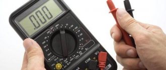
A multimeter is an indispensable digital assistant for any electrician, which is needed to measure resistance, voltage, current, determine polarity, capacitance, frequency, all kinds of electronic transitions and even ambient temperature.
The main device that you should always take with you on a business trip. Sometimes, you don’t have to take other instruments (ammeter, continuity tester, voltmeter), we’ll carry out all the tests with the cartoon. There are, of course, such “specialists,” but you shouldn’t really brag about the fact that you launched a power plant with one unit. And it’s always worth having your own device so as not to borrow from more advanced colleagues. Everyone has their own cartoon, like a car or a guitar.
If you suddenly hold this device in your hands for the first time, then perhaps many questions arise in your head, the answers to which are not obvious at first glance, or contain pitfalls, without knowledge of which you can ruin the device. And the device, in some cases, can cost a lot of money.
How to use a multimeter correctly
Since there are a great variety of multimeters in our world of consumers and manufacturers, in order to satisfy anyone, even the most sophisticated or one tempted by bad experience, there is no point in describing their types and types.
I will conduct the analysis using the example of a personal tester, with whom I have been to many places and whose work I have become accustomed to. The beginning of using a multimeter usually lies in its back part, sometimes this part is under a protective cover. We are talking about a battery. Removing the cover correctly at first may seem difficult and even impossible, but once you get the hang of it, the task turns out to be elementary. In my case it is a 9 volt battery that is hidden under the cover. The cover is unscrewed using a “+” screwdriver. The battery sometimes runs out, especially if you do not turn off the backlight, and then you should replace it with a new one.
If everything is fine with the battery, then the device can be turned on. There are options here. In my case, the device is turned on by the on button, and turned off by the off button, which are combined in one.
There are options where turning on and off is carried out by rotating the central rotating disk. The off position in this version is in the extreme left position (-90 degrees).
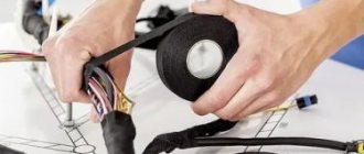
With any type of measurement, it should be taken into account that a wire or radio element may have insulation, both in the form of a sheath and in the form of paint. Sometimes this shell will have to be cut off and the paint cleaned off, for example with a screwdriver. Naturally, cleaning is not under voltage.
Depending on the required tasks, we will connect the wires (they are also called ends, but you should not put them in water (just kidding)) into certain holes on the device. Next, we will analyze the use of each type of measurement in more detail, but I will immediately make a reservation about one point. The device has an acceptable value in each measurement mode.
In the case of the M4583, this information is written at the bottom under the holes. Voltage up to 1 kV, current up to 10A, current up to 200. That is, a current of more than 10A (if you don’t know, the current is dangerous for humans) should not be measured with a device, as it will burn out, break, become unusable, and will not work .
There is immediately a possible second mistake - the ends were connected to 200mA, but they thought it was 10A. As a result, you will need to buy a fuse. To find the fuse, you need to unscrew the back cover and take out this baby. Purchased at a local radio market or market in accordance with the rating written on the fuse. Or just show it to the seller and he will select the one you need.
After turning on the multimeter, you need to insert the ends. There are 4 obvious options and three not so obvious ones. We have two ends and four holes.
- total and “VOmHz” - we measure resistance, DC and AC voltage, frequency
- total and mA - we measure current up to 200mA (different devices have different values)
- total and A - we measure current up to 10A - usually clamps are used for this type of measurement, since until the need for such a measurement arises, this type of measurement becomes unavailable due to improper use of the device by a young specialist.
We turn on the device - insert the wires into “common + VOhmHz” - set the “continuity diode” sector on the circle and connect the ends. There are two options here - if it rings, then the device is working. If it doesn’t ring, then either your dialer is broken, or one or both of the wires are faulty, or you didn’t set it for dialing - in general, then the device may be faulty. Instead of dialing, you can look at the screen in resistance mode. With closed ends it should show a value close to zero, with open ends - 1.
Usually, when we need to measure something, we present an approximate value of what we will get. That is, the voltage in the socket is 220V, the current in the secondary circuits is up to 5A, in the automatic control circuits 20mA. Although, no, this information is not always known. Therefore, when working with a multimeter, we always set the maximum limit of the measured value. Even if the outlet has 220V, it is better to set it to 700V and then turn the dial to decrease. By reducing the limit, we increase the measurement accuracy. At least that's what I think.
Determination of polarity by alternative methods
If it happens that you don’t have a multimeter at hand, but you need to find the polarity, you can use alternative and “folk” means.
For example, speaker wiring charges are checked using a 3-volt battery. To do this, you need to briefly touch the wires connected to the battery to the speaker terminals.
If the cone in the speaker begins to move outward, this will mean that the positive terminal of the speaker is connected to the positive terminal of the battery, and the negative terminal to the negative terminal. If the diffuser moves inward, the polarity is reversed: the positive terminal is connected to the minus, and the negative terminal to the plus.
If you need to connect a DC power supply or battery, but there are no polarity markings on them, and you don’t have a multimeter at hand, plus and minus can be determined by “folk” methods using improvised materials.
The easiest way to determine polarity that you can use at home is to use potatoes. To do this, you need to take one raw potato tuber and cut it in half. After this, two wires (preferably of different colors or with any other distinctive sign) with their bare ends are stuck into a cut of potato at a distance of 1-2 centimeters from each other.
Read also: Ignition switch KAMAZ Euro 4
The other ends of the wires are connected to the constant current source being tested, and the device is turned on (if it is a battery, then after connecting the wires, nothing else needs to be done) for 15-20 minutes. After this time, a light green spot will form on the potato cut around one of the wires, which will be a sign of a positive charge on the wire.
The second method also does not require any special devices or tools. To determine the polarity of the wires of a DC source, you will need a container of warm water into which two wires connected to the power source are lowered.
After connecting the device to the network, gas bubbles (hydrogen) will begin to appear around one of the wires - this is the process of electrolysis of water. These bubbles form around a source of negative charge.
The following method is suitable if you have an unused, working computer cooler. The method for determining polarity using this method is that the cooler must be powered from the uninterruptible power supply being tested. But often there are three wires in coolers:
- black, responsible for negative charge;
- red, responsible for positive charge;
- yellow is the speed sensor.
In this case, the yellow wire is ignored and is not connected anywhere. If, after connecting the cooler to a constant voltage source, the cooler starts to work, then the polarity is determined correctly, the plus is connected to the red wire, and the minus is connected to the black. And if the cooler does not work, this will mean that the polarity is incorrect.
Also, if a multimeter is not available, the positive and negative contacts of the battery can be determined using an indicator screwdriver.
To do this, you need to touch the indicator to one of the battery terminals, press your finger to the back of the indicator (to the contact on the handle), and touch the second terminal of the battery with your hand.
If the indicator starts to light, then the charge of the tested terminal with which it is in contact has a positive value, and if the indicator does not light up, the terminal is negative. But this method of determining polarity has one drawback.
If the battery is discharged or damaged (broken), the indicator will light up when in contact with both terminals, making it impossible to determine the battery poles.
It is known that an LED in operating condition passes current only in one direction. If you connect it inversely, then direct current will not pass through the circuit and the device will not light up. This happens because, in essence, the device is a diode; it’s just that not every diode is capable of glowing. It turns out that there is a polarity of the LED, that is, it senses the direction of current flow and works only in a certain direction.
Determining the polarity of the device according to the diagram is not difficult. The LED is indicated by a triangle in a circle. The triangle always rests on the cathode (sign “−”, crossbar, minus), the positive anode is on the opposite side.
Read also: How to start starline autorun
But how to determine the polarity if you are holding the device itself in your hands? Here in front of you is a small light bulb with two wire leads. To which wiring should the plus of the source be connected, and to which to the minus, for the circuit to work? How to correctly set the resistance where is the plus?
The first way is visual. Let's say you need to determine the polarity of a brand new LED with two leads. Look at its legs, that is, its conclusions. One of them will be shorter than the other. This is the cathode. You can remember that this is a cathode by the word “short”, since both words begin with the letters “k”. The plus will correspond to the pin that is longer. Sometimes, however, it is difficult to determine the polarity by eye, especially when the legs are bent or have changed their sizes as a result of the previous installation.
Looking into the transparent case, you can see the crystal itself. It is located as if in a small cup on a stand. The output of this stand will be the cathode. On the cathode side you can also see a small notch, like a cut.
But these features are not always noticeable in LEDs, since some manufacturers deviate from the standards. In addition, there are many models made according to a different principle. Today, on complex structures, the manufacturer puts “+” and “−” signs, marking the cathode with a dot or a green line, so that everything is extremely clear. But if there are no such marks for some reason, then electrical testing comes to the rescue.
Using a power source
A more efficient way to determine polarity is to connect the LED to a power source. Attention! You need to choose a source whose voltage does not exceed the permissible voltage of the LED. You can build a homemade tester using a regular battery and resistor. This requirement is due to the fact that if the connection is reversed, the LED may burn out or degrade its light characteristics.
Some say that they connected the LED this way and that, and it did not deteriorate. But the whole point is in the limiting value of the reverse voltage. In addition, the light bulb may not go out immediately, but its operating life will be reduced, and then your LED will not work for 30-50 thousand hours, as indicated in its characteristics, but several times less.
If the power of the battery for the LED is not enough, and the device does not light up, no matter how you connect it, then you can connect several elements into a battery. We remind you that the elements are connected in series plus to minus, and minus to plus.
There is a device called a multimeter. It can be successfully used to find out where to connect the plus and where the minus. This takes exactly one minute. In the multimeter, select the resistance measurement mode and touch the probes to the LED contacts. The red wire indicates connection to the positive, and the black wire to the negative. It is advisable that the touch be short-lived. When turned on in reverse, the device will not show anything, but when turned on directly (plus to plus, and minus to minus), the device will show a value in the region of 1.7 kOhm.
You can also turn on the multimeter in diode test mode. In this case, when turned on directly, the LED light will glow.
Read also: License for taxi transportation
This method is most effective for light bulbs that emit red and green light. An LED that produces blue or white light is designed for a voltage greater than 3 volts, so it will not always glow when connected to a multimeter even with the correct polarity. You can easily get out of this situation if you use the mode for determining the characteristics of transistors. On modern models, such as the DT830 or 831, it is present.
The diode is inserted into the grooves of a special block for transistors, which is usually located at the bottom of the device. The PNP part is used (as for transistors of the corresponding structure). One leg of the LED is inserted into connector C, which corresponds to the collector, the second leg is inserted into connector E, corresponding to the emitter. The light bulb will light up if the cathode (minus) is connected to the collector. Thus the polarity is determined.
How to determine the polarity of an unknown power source? Let's assume that you come across some kind of constant voltage power supply, battery or accumulator. But... it doesn’t indicate where the plus is and where the minus is. Yes, the matter can be quickly resolved with a multimeter, but what if you don’t have one at hand? Calmly. There are three proven working methods.
Using water
I think this is the easiest way to determine polarity. First of all, pour some water into a container. Preferably not metal. We remove two wires from a power source with unknown terminals, drop them into our water and look carefully at the contacts. Hydrogen bubbles will begin to form at the negative terminal. Electrolysis of water begins.
Using raw potatoes
Take a raw potato and cut it in half.
We plug our two wires from an unknown DC source into it and wait 5-10 minutes.
A light green color appears on the potato near the positive terminal.
Using a PC fan
We take a fan from the computer. It has two terminals, and sometimes even three. The third may be the yellow wire - the speed sensor. But we still won’t use it. We only care about two wires - red and black. If there is a plus on the red wire and a minus on the black wire, then the fan will rotate
If you didn’t guess right, then the blades will stand still.
We use a fan if it is known that the power source voltage is from 3 to 20 Volts. Applying a voltage of more than 20 volts to the fan is fraught with death.
Conclusion
In conclusion, I would like to say that these chips cannot be rolled with alternating current. And as you know, single-phase alternating current consists of two wires - phase and zero. For those who don’t remember how they can be determined, please look here. I would also like to wish you never to confuse the polarity, because “foolproof protection” (reverse polarity protection) is not installed in all electronic devices.
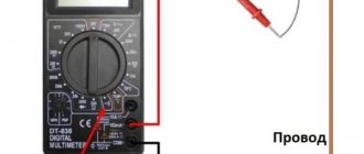
Testing the cable with a multimeter
How can we test the cable for break with a multimeter? If you are not an installer and are far from electricity, then perhaps you should turn to someone who is closer. And if you are a brave seeker of electrical adventures, then perhaps my tips on working with the dialing mode on a multimeter will help you.
If the beginning and end of the cable are in our hands, or the ends of the multimeter reach the beginning and end of the cable, then the situation is simple. For example, we have a three-core cable, but it can also be five or more cores. We set the “continuity” sector by connecting the ends to measure resistance. With one end we touch or sit with the help of a crocodile on any one wire of the cable. We poke the other end one by one into the conductors from the other end of the cable. The core, when touched, will display the value “0” on the screen or the device will ring, and will be the one you are looking for. It is better to immediately mark the beginning and end of the core. Everything is simple here.
The situation is number one. We have one end of the cable in one place, and the other end of the cable is somewhere thirty kilometers away. In general, ringing the cable is useful and vital. Since it happens that the marking and address do not correspond to reality due to errors during installation. If you connect such a cable to the network, the voltage will not go where it should. Or you will test it with AID, put a person at the other end of the cable, apply 50 kV, and at this time an installer will sit at the real end of this cable and cut it. It's always better to be safe than sorry. In general, there are two options.
Option one, when there is a ground loop near both ends of the cable. On one side of the cable we connect the core to the ground; your colleague can do this. At the other end of the cable, we place one end of the multimeter with a crocodile, so as not to hold it, on the ground (grounding wire), and poke the other end along each core. The one that rings will correspond to the one that is connected to the ground at the other end of the cable. We mark the core on both sides and deal with the remaining cores in the same way. Naturally, you need to ring cables that are de-energized (there is no voltage on them) and separated (the cores are not connected to each other).
It will be more difficult to ring if there is no grounding loop, or it is not yet welded or ready. We connect the two wires to each other on one side. On the other hand, we ring the wires together, two should ring. We found those that ring, therefore the third one, which does not ring, is the one we are looking for. We mark on both sides. Same with the others. But here it is better to check all three wires, since if you check only one, it may turn out that it is broken or there is a gap. And so, we check in pairs that they are whole.
Here are a couple of ways to check wires and cables for breaks. This can be done either with a multimeter or with a dial gauge, which you can build yourself.
Another note, you should not think that if there are three wires in the cable and, for example, all three are of different colors at the input, then at the output they will be the same three colors.
There was a case when there were pink red and blue wires at the input, and the same at the output. And when dialing, they don’t ring by color, although there is a distance of five to ten meters across the floor from the machine to the pantograph. The fact is that along the way it may turn out that the cable consists of several parts that are connected through a terminal block or coupling and the order of the cores is confused due to this transit connection. Therefore, you should always call and not believe the flowers.
How to correctly determine the polarity on wires in a car
If the voltage on the car is checked, the course is set to search for a constant one. 20W is the correct setting if you are testing the battery. Therefore, you need to adjust the dial to the desired range/setting and connect the probes to whatever component you want to get a reading for.
You may be interested in Converting watts to kilowatts
How to check a headlight with a multimeter
Multimeter
To check the headlight wiring, you need to find the ground wire. There are 2-4 wires coming from the connector that connects to the light bulb. Where there are two or three wires, only one of them is ground, while four-wire connectors will have two grounds.
To test the wires on the headlight, you need to set the multimeter to resistance. You can place one of the probes on the ground and the other on the negative pole of the car battery.
Note! If continuity is not read, then there is a problem with the ground wire, meaning it needs to be replaced.
How to Test a Car's Ground Wire Using a Multimeter
To test ground wires, start by measuring resistance. Test along the wiring to check the reading is 5 ohms or less. If it exceeds, you will need to check the wire further. You need to switch the multimeter to constant voltage and turn on any electrical part that is having problems. It's worth double-checking the wire to make sure the reading doesn't exceed 0.05V. If it does, you'll need to use a different ground location or use a tie strap.
How to Check if a Fuse Has Blown Using a Multimeter
Troubleshooting a fuse using a multimeter is extremely easy. You need to set the multimeter to the lowest ohm setting and place the probes on both sides of the fuse covers. Fuses do not have polarity, so the contacts used will not show values.
Circuit breakers
Note! If the resistance value is very low, then the fuse is working perfectly. If the resistance value does not change after connecting the contacts, the fuse has blown.
You can also test the fuse using a test light. You need to turn on the key and touch both sides of the fuse with the tip of the test light. If it lights up, the fuse is good. If it does not light up, the fuse needs to be replaced.
How to use a multimeter from a car battery
If you're having trouble starting your car, one of the most common reasons is a weak battery. This is something that can be easily checked using a multimeter, which will also give an accurate idea of how much charge the battery actually has left. Testing your car battery first is a great way to rule out a likely cult for many electrical problems.
When testing a car battery, you need to check the voltage by setting the multimeter to 20 V DC. It is necessary to connect contacts to both terminals of the battery that match the color. It is better to turn on the headlights to get accurate information regarding the charge.
Important! The headlights must be turned on when the engine is stalled.
In most cases the reading will be somewhere between 11.8 V and 12.6 V. The higher the voltage reading, the more charge there is in the battery. A reading of 12.5V means the battery is almost fully charged, while a reading of 11.9V means the battery should be replaced soon.
You might be interested in this: Features of a three-phase network
Checking the charger
Electronic devices use adapters to convert alternating current supplied from wall outlets to direct current. Once converted to direct current, current flows in one direction, hence the term direct current.
What color is the positive wire on the charger?
Note! One wire is positive, which conducts current to the device, and the other is negative, which completes the circuit. The direction of flow is called polarity and is marked on chargers using a diagram. If there is no diagram on the charger, it is worth checking the polarity.
The color polarity of the charger wires does not matter.
To determine if the charger is fit for use, do the following:
- Connect the charger to a power outlet.
- Turn on the multimeter and set the settings to DC voltage. Most multimeters indicate this setting as VDC.
- Insert the red positive contact into the hole in the charger tip.
- Touch the black negative terminal and the outer metal part of the charger tip.
- Monitor the multimeter readings. You may see a positive or negative number indicating the DC output voltage of the charger. If the number is positive, then the polarity on the inside of the charger tip is positive. If the number is negative, then the polarity inside is negative.
Measuring voltage with a multimeter
High voltage is life-threatening, although current is more dangerous, but they do not flow without one another. In general, before measuring voltage, it is necessary to understand what type of U we are dealing with and what its order of magnitude is. Most multimeters allow you to measure both direct and alternating voltages up to 1000V. My device can measure up to 1000V DC and up to 700V AC. To measure, we connect the ends to the “common” and “volts” connectors. Then we set the type of voltage and its value on the rotating wheel. For example, to measure the voltage in an outlet, you need to set the AC voltage to 700 volts. For the battery, a constant 20V for the crown or 2V for the finger will be sufficient. Since we measure the voltage parallel to the circuit, then, having set the values on the device, we touch the battery terminals with the probes or insert them into the holes of the socket. The screen will display the voltage value in volts. If it is much less than the set limit, then you can reduce it for a more accurate measurement. When measuring, it is necessary to hold on to the insulated parts of the measuring wires and monitor their condition so that there are no kinks or breaks.
How to determine phase and zero with a multimeter
Following the voltage measurement, it may be necessary to determine the phase and zero using a tester. Options are also possible here. For example, we have two wires that come out of the wall. And they are not signed. And we need to understand where our phase is and where our zero is. How can we do this... Turn on the multimeter to measure alternating voltage. We connect the ends to common and volts. We measure the voltage between the two wires. For example 220V. Okay, so then you can put one end to the side, and with the other, touch each of the wires in turn. One of them will have zero volts, and the second will have 15-30 volts. The one with the volts will be the phase. Is this always possible? Probably not always. After all, there may be 130V on each relative to ground, then you will have two phases in front of you that give linear 220V. But then, probably, even when measuring one end, each will show some volts. But you shouldn’t touch the one that measures zero volts at one end with your hands.
The second, more expensive option is to ring the wires. But are they under voltage? If you know which circuit breaker they come to, then you just need to throw them away from the switch, having first turned it off, and then somehow ring the bell, either by extending the ends, or by being smart. If there are three wires, and for example, we know that one is phase, the second is N, and the third is . Here, determining the phase will be even easier. It is enough to measure the voltage between two wires - this will give you three measurements. For example, it turned out 220V, 220V, 0V. I think the logic is clear. Those with zero volts between them are either zero and zero, or it is a surprise in the form of two wires with the same phase. Oh, and the science of electrical engineering is interesting. In any case, the most reliable way is to test the wires from a de-energized machine.
How to find plus and minus
When a technician deals with electrical wiring, identifying the negative and positive wires plays an important role. Some wires will be clearly marked with a plus (“+„) or minus (“-”) sign. For unlabeled wires, you can first try to check the polarity by looking at physical characteristics such as color or texture. If this method confuses you, you can check the wires with a digital multimeter.
You may be interested in this Features of semiconductors
Some wires have plus and minus
Important details:
- Appliance plugs don't actually have positive and negative sides. Instead, they have one prong hot and the other neutral;
- Positive and negative wires have differences in shape and material. The ribbed one is usually the negative wire on the extension cord. If there is a wire in which both sides are the same color, usually copper with a knurled texture is negative. You need to run your fingers along the wire to determine which side has the ribs. If it is smooth, then it has a positive indicator.
- on speakers and amplifiers, the silver wire is usually negative and the copper wire is positive. They are often held together by a transparent case, so it is easy to determine the polarity of each side. Often the black wire is negative and the red wire is positive. If both cables are black and one has a white stripe, then it is negative, and the plain black is positive.
- You can look in your owner's manual to determine which wires are negative in your vehicle. Each car follows its own color coding system for wires. There is no standard or international system, so it is worth finding the wiring diagram that matches your make and model in your owner's manual.
How to determine plus and minus with a multimeter
Polarity is very important to observe and know. Typically, DC elements, be it a rechargeable battery or a regular battery, have a plus and minus designation. What to do if the inscription is erased? This is where the tseshka comes in handy. After all, its common wire corresponds to the minus, and the voltage wire corresponds to the plus. We connect them to the terminals of the element and if the voltage value is positive, then the overall voltage is set to minus, and the volt voltage is set to plus. If the voltage value has a minus sign, it means the opposite. There are other, more sophisticated ways to determine polarity.
How to determine polarity with a multimeter
In order to find out where the “plus” or “minus” is located, it is better to use a digital multimeter, the display of which shows not only the digital measurement result, but also its sign. This immediately clearly shows whether the tester probes are correctly connected to the wires of the electrical appliance.
The multimeter has a switch that allows you to select the measurement mode. To determine the polarity, it is switched to the DC voltage measurement mode.
The search for polarity occurs as follows:
- Insert the multimeter probe connectors into the sockets on its body. To connect the black probe, the COM socket is used (it corresponds to the negative pole), for the red probe - VΩmA (the positive pole).
- The measurement range is accepted up to 20 V.
- The tester probes are connected to the contacts or wires of the device whose polarity needs to be determined. The device itself is turned on.
- The display will show the value of the measured characteristic. In this case, it is not even the digital value itself that is important, but the sign in front of it.
What could be the result of determining polarity:
- if there is no sign, the probes are connected correctly - red to “plus”, black to “minus”;
- if a voltage with a (-) sign is output, then the multimeter probes are connected to the contacts incorrectly, and at the moment the positive corresponds to the contact to which the black probe is connected.
If the multimeter is analog (that is, with an arrow), if the poles are reversed, the arrow will deviate relative to zero in the opposite direction - that is, a negative voltage value will be determined.
Measuring current with a multimeter
I wrote about how to check the current with an ammeter here. In what cases might we need to know the current strength? Let everyone answer this question for themselves. On the circular disk of the tank there is a section of direct current (=) and alternating current (~). We measure the current by first breaking the circuit. That is, we have current flowing through the wire. We cut this wire and connect a multimeter on both sides of the cut wire. We set the current sector on the circuit with the required limit and turn on the circuit. The device screen will display the circuit amperage. But what if you can’t cut any wires? Hmm... Is there really no way out? But no. There is an exit. Rent current clamps and don't fool yourself! Or select and measure the current with a shunt. Here are some great tips. And under no circumstances put the ends of the drum into a socket when the current sector on the drum is set. The current is measured sequentially into an open circuit. That is, you disconnect the circuit, make a break in the desired wire (or find an existing opportunity to get into the circuit), connect a device securely to this gap, set the current limit, turn on the circuit, measure the current, turn off the circuit, turn off the device, restore the circuit. Since the resistance of the multimeter is small and even negligible, the measurement error will be small. Current in the socket occurs when a load is connected. The formula is simple - P=U*I. A kettle with a power of 2.2 kW at a voltage of 220V will have a current of approximately 10A. And my circuit has an upper limit of 10A, measuring such a current is an extremely dangerous task.
When measuring battery current (= current), you need to do it quickly, otherwise the battery will run out and you will no longer have a battery.
How to determine where the plus and minus are in a socket?
Speaker phasing improves sound reproduction quality. The lack of phase in wide-range speaker systems leads to a sharp drop in output at low and mid frequencies that is clearly noticeable to the ear.
At the same time, the output of high frequencies also decreases somewhat, and the frequency response of the system in this area has pronounced peaks and dips, that is, greater unevenness. Voices and instruments acquire a harsh, unpleasant timbre. In two-way acoustic systems, in the absence of phasing of low-frequency and high-frequency loudspeakers with each other, the same picture is observed.
When the low-frequency speaker is out of phase with respect to the high-frequency one, a dip in the frequency response appears in the band of joint operation of both loudspeakers. The width of this gap will be determined by the properties of the separation filter.
The presence of a dip can lead to a distinctly audible separate sound from the low-frequency and high-frequency loudspeakers. To identify the reasons that cause deterioration in the quality of loudspeakers when their phasing is incorrect, it is necessary to understand the operation of the emitter.
It has been established that when the moving system of the loudspeaker head oscillates, a periodic change in air pressure occurs, located in front of it; the front side will be called the surface of the diffuser facing the listener.
So, when the system moves forward, the pressure increases, and when it moves backward, it decreases. The change in pressure that occurs causes vibration of air particles, that is, the propagation of a sound wave. It is quite obvious that if two moving systems oscillate, then they must oscillate in phase; the forward and backward movement of both systems must occur simultaneously, for example, when S is working, then “the curtains are already moving.”
Otherwise, one of them will create an increase in pressure, and the other will create a decrease. Thus, mutual full or partial compensation of excess pressure will occur. Simultaneity, or in-phase, oscillations of moving systems is ensured if the direction of the current in the voice coil and the polarity of the magnet are the same for both heads. Since factories wind coils and magnetize permanent magnets in a certain way, the whole question comes down to the correct connection of the ends of the windings of the voice coils.
When connecting the heads in series, the end of one and the beginning of the other winding must be connected; When connected in parallel, the beginning and end of the windings are connected together. To make it easier to determine the beginning and end of the windings, the manufacturer uses a special coloring of the lead ends.
Phasing of loudspeaker heads can be done both by ear and by observing the displacement of the moving system. The above applies to speakers that do not contain additional filter elements or a matching transformer.
In the latter case, the phasing process becomes more complicated, since this requires a certain set of special measuring equipment. Let's look at examples of speaker phasing.
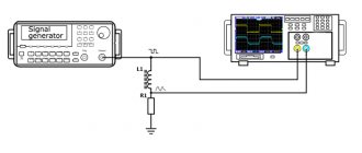
Phasing of single-way acoustic systems. To do this, a low frequency voltage of 50 or Hz is applied to the column. Low-frequency background can be obtained by touching the input circuits of the amplifier.
Finally, an audio frequency generator can be used as a low frequency voltage source. Listening to the level of low-frequency vibrations reproduced by the speaker, change the connection of the audio ends of one of the speakers to the opposite.
If the volume of the reproduced tone drops, then the first activation of the speakers was correct and should be left. If the level increases, the second switching on will be correct. To be more confident in the result obtained, three or four such switches should be made, one after the other.
The final position of the audio ends must be marked, preferably directly at the output terminals of the speaker system. Phasing of two-way acoustic systems. In this case, it is necessary to check the phasing of the low-frequency and high-frequency speakers with each other, if there are several of them in a link, then check the phasing of the links in relation to each other and, finally, the phasing of the low-frequency links in relation to the high-frequency ones.
Checking the fuse with a multimeter
A fuse is designed to protect an electrical circuit from currents exceeding its setting. Before replacing and installing a fuse, you can check it. To do this, touch both sides of the fuse with the ends of a multimeter or connect the probes. Then we set a continuity test on the circuit and if it beeps, it means the signal is passing through and the element is working. If it’s silent, then it’s time to change. If there is no sound signal on the cartoon, we do everything in the same way, only we set not the continuity test, but the resistance measurement. Resistance is low or zero - serviceable, resistance infinity (1) - faulty.
Measuring resistance with a multimeter
In the case of the M4583, it is possible to check resistance in the range from 200 Ohms to 20 MOhms. Resistance is measured across a section of the circuit. We connect common and ohms to the terminals. We place one end on one side, the other on the other. The device will show the resistance value between these two points. By adjusting the measuring range with a circular dial, you can improve the measurement result. You can measure the resistance of electronic components, relays, and windings of electrical machines. If the screen displays a jumping value or unit during measurement, try increasing the measurement limit.
To measure the resistance in ohms of a resistor, you need to remove it from the circuit. This means the resistor has two sides. We plant a tseshka on both sides and measure the resistance. We compare the resulting value with what is written on the resistor itself. In this case, you should not hold the ends of the multimeter and the legs of the resistor with your fingers, since in this case the value will not be entirely correct due to the body’s resistance. In the picture I measured the resistance of the 3 kOhm resistor, it turned out to be 2.98 kOhm.
How to test a relay with a multimeter
When calibrating electrical circuits, it becomes necessary to check individual elements - circuit breakers, relays. Let's take, for example, the RT-40 relay. Firstly we must have an idea about the circuit of this relay. This diagram can be found on the Internet, in the product passport, in your head. Let's see, we have several pairs of contacts and a winding. The test will consist of checking the operation of the contacts and checking the value of the winding resistance. We check the windings in the resistance mode, the value in ohms should be obtained, which can be compared with the passport value, or as long as it is not zero ohms. We check the contacts in the dialing mode, placing the ends of the device on a pair of contacts and simulating the operation of the contacts. In the case of RT-40, we move the contacts to trigger. At this time the bell will ring. In the case of a closed contact, it will immediately ring, and when triggered, the signal will disappear. Likewise, instead of sound, look at resistance. Closed - 0, open - 1. Without applying voltage to the electromechanical relays, contact actuation can be simulated manually.
How to find a broken wiring in a car
If there is a break, the electrical circuit opens. Often the cause of lack of voltage is poor contact in the circuit connector. The block body hides oxidized contacts, so troubleshooting can take a long time. A break may be detected when the pads or wires are swayed.
To find a break in the test, you need to set the multimeter in ohmmeter or continuity mode. The terminals of the device are connected to the ends of the circuit being tested:
- If there is no break, the multimeter will beep (in dial mode) or the resistance will be minimal (in ohmmeter mode).
- If there is a break in the wiring, there will be no sound signal (in dial-up mode), but the resistance will be very high (in ohmmeter mode).
Measuring temperature with a multimeter
In the case of determining weather conditions, you will need a special wire that comes complete with the device, at the end of which there is a thermocouple, or something that measures the temperature. This can be seen in the photo. The wire is plugged into a special connector, the temperature measurement mode is selected and the value in degrees Celsius is shown on the screen.
Checking the cable insulation resistance with a megohmmeter
AID-70 device