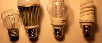
Fluorescent and other types of economical light sources often fail before the service life stated by the manufacturer. Therefore, many people strive not to buy a new copy, but to independently restore the old one, which has not yet reached its full capacity.
Let's consider how to repair a standard energy-saving lamp used in everyday life or at work with your own hands, and also whether it is worth repairing it at all and what could be the main reasons for its malfunction, how to find them, what rules must be followed when disassembling such a lighting device, what repairs the procedures to be performed, what the essence of preventive measures is and what modernization of the lamp can be undertaken in this case.
Is it worth repairing energy-saving lamps?
Do-it-yourself repair of an energy-saving lamp is advisable when you have access to several copies that have failed for one reason or another. This will ensure the availability of a large number of components necessary for restoration work. It is unlikely that it will be possible to repair one damaged light bulb on its own - it will simply be unprofitable, because it will require:
- Spend time searching for spare parts.
- Raise additional funds for travel and purchase of components.
- It is more profitable to purchase a new lamp than to purchase separately components for its repair.
Therefore, it makes sense to undertake the restoration of energy-saving lamps only if at least 4-5 similar copies are immediately available. With effort and enough experience, you can assemble one working one from several lighting devices with your own hands.
Note! Not all elements of burnt-out energy-saving lamps are suitable for repair. So, over time, after a long period of operation, the inner surface of the bulb darkens, and the light output drops, the brightness deteriorates. In addition, in some models, after restoration, the start-up delay occurs - the ignition is delayed up to several seconds.
Causes of failure of LED lamps
Before you begin repairing energy-saving lamps, you should understand the cause of the breakdown. If, when trying to turn on the light source, it does not manifest itself in any way, you should pay attention to the condition of the bulb.
In addition, closer to the expiration of the warranty period allocated by the manufacturer for the operation of the lamp, the phosphor burns out, as a result of which you may notice that the light has become less bright. In this situation, disassembling the lamp body is useless, since the bulb cannot be repaired.
If the operation of the lighting device stopped much earlier than the lamp service life specified by the manufacturer, then, most likely, the cause of the device breakdown can be considered a burnt-out electrode thread or one of the mechanisms that regulates the start-up of the device. In both situations, you will need to disassemble the lamp housing.
Upon a detailed study of the design of the device, you will notice that at the base of the flask there is a housing where the ballast, consisting of two parts, is located. It will need to be opened; to do this, just use special latches. You can disconnect the remaining parts of the case using a simple screwdriver.
It is necessary to perform all the presented manipulations slowly, as there is a risk of damaging the cables. The functionality of the electrodes is checked using a multimeter. As a rule, the resistance of the threads varies from 10 to 15 ohms.
In addition, among the reasons for lamp failures are the following:
- voltage drops - in this case, the LEDs will remain undamaged, but the driver may stop functioning;
- incorrect selection of the lamp - in the absence of high-quality ventilation, the driver overheats, which negatively affects its functioning;
- presence of manufacturing defects - you should not buy too cheap devices, since they probably have some defects.
Causes of light bulb failure
To repair an energy-saving lamp, you first need to determine with your own hands the true cause of its malfunction. To do this, you need to disassemble it, following a special algorithm of actions, as well as preparing in advance the following set of necessary tools:
- A flat-head screwdriver or a small knife with a thin blade.
- Multimeter.
- Soldering iron with components for soldering, power no more than 30 watts.
The cause of the breakdown can only be determined by completely dismantling the lamp, following the instructions:
- Disconnect the flask from the body with the base. It is extremely important to remain extremely careful during this procedure, as both the bulb and the base must remain intact. To do this, you need to insert a screwdriver or knife into the technical gap between these two elements and turn it, moving it around the entire circumference. The system is closed with latches, similar to those used in cell phones.
- Dismantle the conductors going to the channel thread. When the case is opened, you will see a pair of thin wires running from the board to the bulb to power the spiral inside it. They need to be disconnected by unwinding them from the special pins.
- Make sure the filament is working properly. In the glass part of the lamp there is always a pair of spiral-shaped elements for illumination, with a resistance of no more than 15 Ohms. They should be checked for integrity using a multimeter. If they are in good working order, then the cause of the breakdown is the ballast, but if on the contrary, then, most likely, the last component is operational.
When dismantling the bulb from the base of an energy-saving lamp, you must do it yourself so as not to tear off the thinnest conductors that power the spirals.
Lamp 1 - Volta
20W, base E27
Failure: the lamp does not light.
The video shows in sufficient detail and clearly the process of disassembling and assembling the lamp body, dismantling the filaments, etc. mechanical work, which may be of interest to those who are new to repairing any similar energy-saving lamps (this is the first lamp in my life that I have disassembled).
Repair: replacement of a swollen high-voltage electrolytic capacitor and burnt-out inductance in the power circuit.
The pinout of transistors must be checked with a tester! It may vary from manufacturer to manufacturer!
Troubleshooting
After carrying out the above described manipulations, in order to repair a burnt out lamp with a 100% guarantee, it is necessary to detail the cause of the breakdown. First of all, you will need to inspect the board for visible damage. On the SMD side, these can be all kinds of deformations of the electrical circuit tracks - in the form of blackening, burn marks, cracks, chips, etc. On the other side, you need to look for burnt semiconductor elements, swollen capacitors, and remnants of a damaged winding of the transformer module.
Electronic ballast fault
First, you need to visually inspect the ballast for cracks, chips, etc. This way you can see burnt-out parts of the circuit that are clearly noticeable. Well, if there are none, a multimeter will again help. It is necessary to ring all the main elements of the electronic ballast.
ESL disassembled
The main elements that need to be checked by the tester are as follows:
- The thermistor (RTS) is a protective device with a positive temperature coefficient of resistance, providing an “easy start” of lamps without blinking for 2-3 seconds with heating of the electrode spirals. The presence of the RTS component makes it physically possible to achieve a service life of 10,000 hours or more, making it practically independent of the number of lamp on-off cycles.
- The starting capacitor is a high-voltage element involved in the process of “igniting” the lamp. The higher its rated voltage, the higher the fault tolerance limit.
- Capacitive filter – smoothes out ripples of rectified DC voltage and ensures flicker-free operation. Depending on the model, it has a different nominal service life. If it is chosen incorrectly, it dries quickly, loses its characteristics - the lamp quickly fails.
- A current-limiting choke is a device that stabilizes and limits the lamp current.
- Switching bipolar transistors are key elements of an electronic ballast (electronic ballast), i.e. electronic ballast. If the transistors are not selected optimally, they are susceptible to rapid breakdown due to overheating, which entails failure of the entire lamp.
- A fusible resistor is a protective device that ensures emergency disconnection of the lamp from the power supply and prevents ignition in the event of overloads and short circuits.
It is also necessary to check the serviceability of the diode bridge. To do this, there is no need to desolder it from the electronic ballast; each diode can be ringed individually on site.
Parsing rules
Repairing an energy-saving lamp with your own hands is preceded by disassembling and checking its main components in the following order:
- Fuse.
- Flask.
- Transistors and resistors.
- Capacitors.
Let us consider in detail the main features and rules for do-it-yourself dismantling of each of them.
Fuse
The fuse is located in the middle of the core connecting the contacts of the base and the printed circuit board. It is docked with a resistor module and must be equipped with an insulating casing. To determine its performance, you need to ring it with a multimeter. To do this, one probe of the device must be in contact with the central base terminal, the other with the junction of the safety module conductor with the board.
When this component is fully operational, the measurement result should be 10 ohms, otherwise the device will display one. The malfunction can be eliminated by replacing the old one - by biting it off to the very base of the case - so that for the convenience of soldering the new one, the longest lead from the base remains.
Flask
Before proceeding with the board elements, you need to check the filaments of the bulb. There are two of them in an energy-saving lamp. Their resistance should be the same and equal to approximately 10-11 Ohms. If the difference between them is significant, then one of them has burned out. You can restore it with your own hands if you solder a resistor of similar resistance parallel to it.
Transistors and resistors
As a rule, in the circuit of an energy-saving lamp there are only a couple of transistors. However, to test them, you will have to unsolder them - due to the bridging of the pn junction in the transformer winding. Doing this yourself with enough experience and a small soldering iron is not so difficult. In case of malfunction, they must be replaced with analogues with the same characteristics. Resistors are also checked with a multimeter. The indicators of their operating parameters are indicated on top of the body.
Advice! To verify the authenticity of a breakdown or operability of a particular module, you can perform a similar part-by-part test on the circuit board of a working lamp, having first disassembled it.
Capacitors
The capacitor is checked in the same way as described above. If necessary, replace it with a new one. You can rely on its appearance as a hint during checking. A broken one usually has a swollen body or smudges. In most cases, it is this module that is the main culprit in the failure of energy-saving lamps from Chinese manufacturers.
We identify faulty elements on the ballast board.
Fuse.
First of all, we check the fuse. It's easy to find. One end of it is soldered to the central contact of the lamp base, and the other to the board. A tube made of insulating material is put on it. Typically, fuses do not survive such a malfunction.
But as it turned out, this is not a fuse, but a half-watt resistor with a resistance of about 10 ohms
, and was burnt out (in a cliff).
The serviceability of the resistor is easily determined. Place the multimeter in resistance measurement mode to the “ continuity
"or "
200
" and take the measurement.
If the fuse resistor is intact, then the device will show a resistance of about 10 ohms
, but if it shows
infinity
(one), then it is broken. You can read how to measure resistance here.
Here, place one multimeter probe to the central contact of the base, and the second to the place on the board where the lead of the fuse resistor is soldered.
One more thing. If the fuse resistor turns out to be burnt out, then when you bite it, try to bite it closer to the resistor body, as shown on the right side of the top picture. Then we will solder a new resistor to the terminal remaining in the base.
Bulb (lamp).
Next, check the resistance of the bulb filaments. It is advisable to unsolder one pin on each side. The resistance of the threads should be the same, and if it is different, it means one of them has burned out. Which is not very good.
In such cases, experts advise soldering a resistor parallel to the burnt spiral with the same resistance as that of the second spiral. But in my case, both spirals turned out to be intact, and their resistance was 11 Ohms
.
The next step is to check all semiconductors for serviceability - these are transistors
,
diodes
and
zener diode
. If you don’t know how to test a transistor or diode, then read the article on how to test a transistor with a multimeter.
As a rule, semiconductors do not like working with overloads and short circuits, so we check them carefully.
Diodes and zener diode.
There is no need to unsolder the diodes and zener diode; they already connect perfectly right on the board. The direct resistance of the pn junction of the diodes will be within 750 Ohms
, and the inverse must be
infinity
. All my diodes turned out to be intact, which made me a little happy.
Double-anode zener diode
, therefore, in both directions it should show a resistance equal to
infinity
(one).
If some of your diodes turn out to be faulty, then you need to purchase them at a radio components store. 1N4007 are used here
. But I couldn’t determine the value of the zener diode, but I think that you can install any one with a suitable stabilization voltage.
Transistors.
The transistors, and there are two of them, will have to be unsoldered, since their base-emitter pn junctions are shunted by the low-resistance winding of the transformer.
One transistor rang both right and left, but the second was supposedly intact, but between the collector and emitter, in one direction, showed a resistance of about 745 Ohms
. But I didn’t attach any importance to this, and considered it faulty, since this was the first time I was dealing with transistors of type 13003.
I couldn’t find transistors of this type in a TO-92 package, so I had to buy a larger one in a TO-126 package.
Resistors and capacitors.
They also need to be checked for serviceability. But what if.
I still had one SMD resistor, the value of which was not visible, especially since I did not know the circuit diagram of this ballast. But there was another similar working energy-saving lamp, and it came to my rescue. It shows that the value of resistor R6
is
1.5 Ohm
.
To finally make sure that all possible faults were found, I rang all the elements on the working board and compared their resistance on the faulty one. And he didn’t solder anything.
In the end, the price was not at all expensive:
1. Transistors 13003 – 2 pcs. 10 rubles each (in the TO-126 case - I took 10 pieces); 2. SMD resistors - 1.5 Ohm and 510 kOhm, 1 ruble each (I took 10 pieces); 3. 10 Ohm resistor – 3 rubles per piece (I took 10 pieces); 4. Diodes 1N4007 – 5 rubles per piece (I took 10 pieces just in case); 5. Heat shrinkage – 15 rubles.
Ballast repair
To perform basic repairs to the ballast of an energy-saving lamp with your own hands, you first need to inspect it externally. As a rule, this allows you to immediately determine the cause - swollen capacitors, burnt tracks, deformed transistors, etc. However, replacing them does not guarantee the restoration of the lamp's functionality. Therefore, a more in-depth check of the main elements of the entire electrical circuit will be required.
A typical electronic ballast circuit for an energy-saving lamp is as follows:
Symbols on the diagram
L1 (coil) and C1 (capacitance) play the role of a filter element against interference. In cheap models, a simple conductor is installed instead.
L2 (coil) with a given number of turns (250-350) of a conductor 200 microns thick on a ferrite rod. Externally, the module is shaped like the letter W and looks like a transformer unit.
T1 (transformer) contains 3-9 turns of 300 micron conductor on a firrite ring.
FY1-0.5 A (fuse), as a rule, is not included in Chinese models; instead, a resistance of several ohms R1 is installed (most often this element burns out).
Malfunctions of the elements of the ballast unit
Checking the condition of board parts involves a thorough inspection of each element of the circuit on both sides. Burnt radio components are immediately visible. It happens that a small section of the track deteriorates near a burnt resistor. This occurs due to a short circuit when the element fails.
Important! If the inspection shows the presence of burnt components, you should think about the operating mode of the lamp. Such damage indicates that the lamp was working too hard, was overloaded or overheated.
Flask
First, the resistance of the filaments is measured with a multimeter. Their calculated resistance is 10-15 Ohms. This indicator should be approximately close for all threads. A significant difference in the parameter value indicates that one of the threads has burned out. To correct the situation, it is recommended to solder a resistor with a resistance equal to the resistance of the second spiral into the circuit parallel to the burnt component.
Restoring a light bulb in this way is more of a half-measure than a full-fledged repair, because it does not restore the original functionality of the lamp. After installing the resistor, only one filament will work, so the original brightness will no longer be obtained. If both threads are operational, you will have to look for a fault in the electronic circuit.
We recommend reading: how to check a light bulb with a multimeter
Checking ballast components
- fuse . This component is located directly on the board. If it is not there, then it is replaced by a resistor, which is located between the board and the central contact of the base. The top of such a resistor is covered with insulating material (heat shrink). We check the fuse with a multimeter in continuity or resistance measurement mode. The resistance of the working fuse should be close to 0 ohms. If a resistor is used instead of a fuse, then to check it, one multimeter probe is placed on the central contact of the base, and the other is placed on the terminal on the board to which the wire with the resistor is soldered. Normally, the device should show a resistance in units of ohms. To repair, a faulty fuse or resistor is replaced with a new one.
- diode bridge for voltage rectification . As a rule, it consists of 4 diodes, which are best unsoldered for testing. The test is also carried out with a multimeter in diode test mode.
- filter smoothing capacitor . This element often fails in cheap Chinese-made energy-saving lamps. Moreover, before turning off, the lamp exhibits “symptoms” in the form of a hum, unstable operation, and slight blinking in the off mode. The malfunction of the capacitor is easily determined visually - it darkens, swells and leaks.
- high voltage capacitor that maintains the charge in the bulb. Very often, energy-saving lamps fail due to breakdown of this radio component. In this case, the lamp itself stops burning, but a slight glow is observed near the electrodes. To repair a lamp, you need to integrate a radio element with similar parameters into the circuit.
- Transistors must be unsoldered before testing, because they are shunted by one of the transformer windings. If one of these elements turns out to be non-working, it is simply replaced with similar parameters. Given the appropriate performance characteristics, you only need to think about whether the dimensions will allow it to be successfully installed.
With proper diagnosis, purchase and installation of replacement radio components, repairing an energy-saving lamp yourself is inexpensive. Elements of the ballast are sold in radio parts stores for 5-10 rubles apiece.
It is advisable to buy parts for several repairs in advance, so as not to run around for 1-2 diodes or capacitors each time, but to quickly fix the problem that has arisen.
Reassembly
Before assembling an energy-saving lamp after repair, you need to check whether it is working properly. It is enough to connect the wires without snapping the electronic ballast housing, and screw the base into the socket. If there is light, the repair was done correctly. Then you can put the chip in its place and fold the case. Of course, when checking, you must follow safety rules. If in doubt, fully assemble the lamp before testing.
Repair for burnt thread
All repair work related to the filament leads to the fact that the ballast of the energy-saving lamp will work in abnormal mode. With a stable power supply, it can function for up to 1.5 years, and in case of overload, the ballast module will immediately burn out. Therefore, it is permissible to use only high-quality, functional elements in the circuit.
The main repair procedure in the event of a burnout of one thread of the channel is reduced to bridging it with a resistor Rsh of similar resistance. The diagram below clearly shows the result of such a restoration:
However, in practice, the introduction of a resistor module with similar characteristics into a circuit will lead to burnout of the components already after a quarter of an hour of operation of the light bulb. Therefore, it is better to install a 22 Ohm option with a power of at least 1 watt.
How do energy saving lamps work?
Small fluorescent lamps, popularly known as energy-saving or “housekeeper” lamps, are one of the types of gas-discharge lamps. Their design includes a base, a bulb and a controller. The latter is most often built inside, which makes the entire device more compact.
Discharge lamps work by releasing electrons from electrodes that are heated by voltage. Inside the bulb, these electrons react with the gas, resulting in ultraviolet light. The human eye does not perceive ultraviolet radiation, so the lamp uses a phosphor. It neutralizes UV rays and only pure bright light is scattered from the lamp.
Assembling an energy-saving lamp
After all components have been checked and restored, the energy-saving light bulb must be tested and then assembled. If any components of the case or base were damaged during disassembly, they can be returned to good condition by gluing them with superglue. Upon completion of all repair procedures, you can screw the lamp into the socket with your own hands, after turning off the switch, and check for functionality. An indicator of proper assembly and repair will be a bright, uniform and non-flickering glow.
Prevention
The following can be suggested as do-it-yourself measures to prevent premature failure of energy-saving lamps:
- The chandelier, shade or other external housing of the luminaire must provide sufficient ventilation to dissipate heat and insulation from dust and moisture to prevent overheating and short circuits.
- Buy products only from a trusted manufacturer. This, as well as the installation of a stabilizer at the entrance to the power grid in case of voltage instability, will protect against failure of the ballast.
- Do not violate the operating conditions and use only a high-quality lamp. This will prevent the filament from burning out prematurely.
Upgrading an energy-saving lamp
You can upgrade an energy-saving lamp yourself in order to avoid subsequent repairs or replacement if you introduce an NTC thermistor into its electrical circuit between the spirals, according to the following diagram:
Such a module strictly limits the value of the inrush current, preventing the possibility of their burnout. However, it should not be installed next to an electronic ballast, as it will heat up and soon lose its functionality.