How to repair a car battery charger
Automotive battery chargers (BACs) are available in large quantities on the consumer market. However, any of them can break down over time during use. Therefore, it will not hurt car owners to know how to carry out simple repairs of chargers for car batteries. Of course, a lot depends on the degree of damage: if it is the simplest, there are elements that you can fix yourself.
Main types of ROM
All chargers, based on the principle of operation, are divided into two types: pulse and transformer . A pulse device operates due to the presence of a pulse current converter in it. And inside the transformer charging there is a simple transformer with a rectifier, due to which the ROM weighs more and looks more bulky than a pulse one. Pulse-type devices are considered more reliable in operation, but transformer-type devices are easier to maintain and repair.
How to check the charger
If you decide to charge your car battery at home, but have doubts about your charger, this article is for you. A simple check determines the quality and serviceability of its operation.
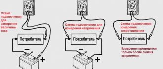
One way is to connect it to the battery and measure the voltage readings with a multimeter. The optimal U in this case is 14 V, a little higher is allowed, up to 14.4 V. If U is less than 13 V, or the multimeter detects its jumps, then there is definitely a malfunction, and it is necessary to carry out some kind of repair of the starting-charger.
If you don’t have a battery at hand, you can check the functionality of the charger with a simple electric light bulb rated for U 12 V. If the light bulb starts to light when connected to it, charging is working normally, and if the light bulb does not light up, the device should be repaired.
How to solve the charging problem
Incorrect operation and choice of charger are the most common reasons why the phone does not charge. A few tips will help you correct errors when using the battery and charger (charger).
- If the battery of a Lenovo phone or other Chinese smartphone is not fully charged, it is necessary to periodically calibrate the battery to equalize the charge level in all cells. To do this, carry out a full cycle of charging to 100% and discharging to 0%.
- Do not use the phone while charging. Charging efficiency decreases, and if the device is connected to a low-power unit, the smartphone will begin to discharge. During charging and use, the battery becomes very hot, which reduces its service life.
- Often there may be several chargers at home, externally identical and with identical current strength. A non-original cable may differ in size by a fraction of a millimeter, which will cause loss of contact when charging. Often in secure phones the socket has a recess and the plug does not reach. When buying a new charger, always take the old one with you to select an identical one.
- A cable length of more than 50 centimeters causes the phone battery to not charge for a long time. Ohm's law is in action, when buying a new charger, choose a cord no longer than 15-20 centimeters.
- If the contact is very weak or occurs intermittently, the first thing to do if the phone does not charge is to turn off Wi-Fi and switch it to “Flight” mode. Leave the device on charge for several hours. During this time, it will be possible to recharge it to the required minimum.
- In a situation where the phone does not turn on or charge, try an alternative method of charging the power bank. It has a long but smooth way of delivering current without surges. This method is especially recommended for owners of Lenovo, Xiaomi, Meizu and other Chinese brands that are sensitive to power surges.
- The power supply of a modern smartphone has an output current of 2 A. Many people have gadgets with a USB connector at home and charge them with one charge. A charger for a fitness bracelet will charge a smartphone in half a day, and old chargers for push-button phones are 2 times slower than new ones. If your smartphone does not charge and shows a crossed out battery icon, buy a powerful power supply.
Advice!
If you have several smartphones with different processors at home, buy a universal power supply that supports Quick Charge, Pump Express, etc.
We carry out simple ROM repairs with our own hands
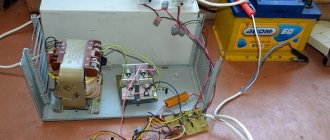
You can try to carry out a simple repair of a car charger and, using the example of a transformer-type power supply, consider how this should be done.
Before carrying out any actions with the ROM, you must turn it off from the network. Carefully remove the cover using a screwdriver and first check the integrity of the wiring. It is quite possible that the problem is loose contacts, and then the problems can be solved yourself using a simple soldering iron.
It happens that some plastic connections between the components of the charger break or melt. In this case, you can also replace them yourself using a soldering iron and suitable available tools.
If all the wires and connections are in place, you should check all other ROM elements in turn . First of all, a multimeter checks the voltage level at the beginning of the electrical circuit, at the input. U is measured along the wire to the point where the wire connects to the transformer itself.
If U jumps or is not there at all, then it is checked:
- fuse (U should be on both sides, on one terminal and on the other, and if there are problems, the fuse must be replaced);
- wiring and plug (U is checked according to the same principle; if there are problems, one or the other is replaced);
- checking the transformer itself (measurements U, if there are any, the transformer is working, if not, you need to check the biscuit switch);
- if the switch is faulty, the output U will be absent but present at the input.
Troubleshooting
A simple repair of a car battery charger can only be done by disassembling the equipment and diagnosing each element.
The procedure for checking and restoring functionality should begin after disconnecting the charger from the network. The cover is carefully dismantled; to do this, the screws are unscrewed with a screwdriver, after which the electrical circuits are diagnosed. When the contact elements become loose, they are soldered again using a conventional soldering iron.
Sometimes the problem lies in the failure or melting of plastic connections between the components of the equipment. Then you can replace the damaged parts yourself using a soldering iron and available materials. If the electrical circuits and contacts on the connections are intact, then the remaining parts of the device are subject to diagnostics.
Using a multimeter, it is necessary to check the voltage level at the beginning of the power line, at the input. The operating parameter is measured along the conductor from the place where the cable is connected to the transformer device.
If there is no voltage or surges are observed, then the following is diagnosed:
- Safety element. Voltage must be present on both sides of the part, on two terminals. If problems are observed, the part must be replaced.
- Electrical circuit and plug for integrity. The procedure for measuring voltage is similar. If there are problems, then the failed elements are replaced.
- The transformer device is being diagnosed. The voltage is measured, if it is present, then the transformer unit is working, if not, then the biscuit switch is diagnosed. When the switching device is not working, there will be no output voltage on the line, but it will be present at the input.
The Maysternya TV channel spoke in more detail about the diagnosis of safety parts, the transformer device and other elements of the board, as well as the repair of the ROM.
After troubleshooting the wiring, transformer mechanism and fuse, the repair procedure will have a number of features:
- The middle part of the circuit, on which five transistor elements are located, represents a temporary relay with keys used to control thyristors. Thanks to the latter, the charging equipment operates in the “Relay” mode. This node in the example under consideration is made on a separate diagram.
- On the second board there is an adjustment unit for the charging current, at the bottom, as well as a mechanism for adjusting the thyristor elements. These parts are designed to determine the current parameter. Thyristors are also located here, which are used to ensure the operation of the device in the “Relay” mode, as well as an automatic protection mechanism for the board. It operates on transistor devices VT1 and VT2. If visual diagnostics of the board showed the presence of a broken conductor, the contact is soldered back.
- The equipment is being activated. If the “Network” indicator light comes on, but there is no voltage at the terminals, it means there is no charge. Diagnosis of diode elements VD1 and VD2 is performed. If these elements are not working, they must be replaced. To disconnect the parts, they are desoldered from the seat, then new elements are soldered.
- The next step will be diagnostics of thyristor elements VS1 and VS2. The part should not pass current in both directions - this indicates its inoperability. Broken parts can be checked with a multimeter, but to identify the problem you will need to assemble a diagnostic probe. Failed parts must be replaced by dismantling and soldering new elements.
- When the diagnostics of all semiconductor components is completed, the electrolytic capacitors are checked. It is necessary to make sure that there is no high leakage current and loss of component capacity. Failed capacitor elements must also be replaced.
- The charging equipment is assembled and activated. If the device operates successfully in all modes, then the repair procedure can be considered complete. If the charger operates only in active load mode, fault diagnosis continues.
- Since in the example under consideration the charge current can be adjusted, the control unit is operational. Otherwise, it is replaced.
- When toggle switch S1 is activated, the terminals of the collector device, as well as the emitter of the transistor part VT1, are closed. This allows you to deactivate the automatic protection mechanism on transistors VT1 and VT2. If the transition from the collector device to the emitter does not open when the toggle switch is turned off, then parts VT1 and VT2, as well as C2, need to be diagnosed.
- The transistor elements under test may behave as working ones, but a break in the emitter junction may be observed as a result of the influence of voltage.
- After checking, the charging equipment is assembled and its operation is diagnosed in all modes. If the resistor elements have been changed, it may be necessary to adjust the discharge time when operating in the “Relay” mode. The time parameter must be set in the range from ten to fifteen seconds. If, instead of a constant resistor element R18, a tuning-type part was used, then the charging time is adjusted to 1.5-2 minutes.
- When the assembly is completed after adjusting the resistors, the operation of the equipment is checked. The discharge time should be 15 seconds, and the charging time should be about 1.5 minutes.
Checking the diode bridge
If you have the desire and ability to diagnose a diode bridge, you must keep in mind that diode bridges can be either monolithic or with the ability to replace one faulty diode with another. In case of malfunction, monolithic bridges are removed and replaced entirely. As for applying voltage to the bridge to check its normal operation, U is supplied to the ROM. If the bridge is working properly, no current will be lost at either the input or output. If the current does not flow at one of these stages, then you need to check each diode separately, identify the faulty one and replace it.
Checking the ammeter inside the ROM
For a more accurate diagnosis of a breakdown, if nothing was detected during previous checks, you should check the ammeter. If, when checking the voltage in the ammeter, it is absent, but when connecting its terminals to each other, U appears, it means that the ammeter is broken and it is time to repair it.
Thus, it is possible to carry out fault diagnosis and simple repair of chargers for automobile lead-acid batteries on your own. But when the battery is not charging due to a malfunction of the device, and the car enthusiast does not have the necessary skills in the field of electronics, or he was unable to repair the ROM himself, it is best to turn to specialists. As a last resort, you can try to charge the battery without a charger.
Well, home handymen may also be interested in learning how to make a load plug for a battery with their own hands.
Charger repair
So, a visual inspection did not allow us to find the cause of the breakdown, therefore, it is still impossible to do without repairs. At the initial stage, we will check the plug for damage and test the power cord through which power from the network is supplied to the device. There are situations when the cause of the breakdown lies precisely in the supply wire.
Using the simplest tester that is at hand, we will measure the voltage along the entire wire, starting from the plug and ending at the junction with the transformer winding. The criterion for a malfunction will be a complete absence of voltage or its intermittent values.
If the supply wire is normal, then the car battery charger will have to be repaired by replacing certain components of the internal operating circuit. And this already requires skills in handling electrical measuring instruments and knowledge of basic safety rules.
Malfunctions and methods for their elimination
It is necessary to search for the cause of a memory failure step by step, moving from one element to another, adhering to the diagram of their connection to each other.
Any part of the charger may be faulty. The standard equipment of the charging device includes:
- A fuse whose main function is to prevent failure of the main structural elements due to overload or short circuit. We start by checking it: a serviceable element will definitely show the presence of voltage parameters on both terminals, otherwise replacement is required.
- Transformer – converter of 220 V mains voltage into the operating voltage required for the operation of the device. We measure the voltage value at the output terminals of the transformer - if it is missing, it is necessary to replace this part.
- The galet switch is responsible for smoothly adjusting the voltage while charging the battery. It is diagnosed in several positions: if the voltage at the output is zero, it must be replaced. Moreover, the input voltage must be present.
- At the last step, we diagnose the diode bridge, which converts alternating current into direct current, and the ammeter, which provides the ability to control the charging current. How to do this is described below.
It is in these components that you should look for the cause of the malfunction of the car battery charger, if previous actions did not lead to the desired result.
There may be several malfunctions, so all structural elements should be checked.
We carry out simple repairs of the charger with our own hands
We present to you recommendations on how to repair a car battery charger with your own hands:
- A malfunction of the supply wire plug is eliminated by replacing it: disconnect the non-working plug from the wire, take a usable element and connect it to the wire cores.
- The supply wire is not suitable for use: disconnect it from the plug and the transformer winding. We install a new one in place of the non-working one, carrying out installation by analogy with disassembly.
- Replacing a fuse requires care and attention. Carefully remove it from the body and install the worker in this place. If the fuse link has melted due to improper connection to the terminals, it is recommended to purchase a special wire block from an auto parts store and place a fuse in it.
- As for repairing or replacing more complex parts: transformer, biscuit switch, diode bridge and ammeter, this is an activity for professionals. This requires good knowledge in the field of electronics and physics, as well as experience in performing similar work.
Checking the diode bridge
A diode bridge is a complex structural element consisting of four diodes. First, the presence of input and output voltage is determined. If it is, then the cause of the malfunction is something else. If the measuring device shows a lack of output voltage, then the breakdown should be looked for in the bridge configuration.
Causes of failure
The most common reasons why a phone refuses to charge:
- battery failure due to long-term use;
- dust getting on the contacts of the device;
- faulty USB cable or phone charger;
- technical failures in the software;
- slow charging via a computer or laptop;
- smartphone RAM is full due to resource-intensive programs.
Most of these reasons can be resolved on your own without turning to specialists. In order to recognize the cause of a breakdown, you need to know their symptoms and manifestations.
Charger testing
Having completed the diagnostics and eliminated the cause of the charger failure, you should make sure that it is working before you start charging the battery.
Using a multimeter that is universal in all respects, we will test the basic parameters of the device:
- Having switched the multimeter to ammeter mode, we connect it in series to the circuit, having previously set the required current value on the charger - one tenth of the capacity. The instrument readings must correspond to the set value on equipment that is in working order and ready for use.
- Now let's switch the multimeter to voltmeter mode and connect it in parallel to the terminals of the device for charging. If the malfunction was actually eliminated, then the voltage value that the equipment is capable of producing during operation will be more than 13.2 V. Otherwise, the charger is unusable.
How to repair a car battery charger yourself
The battery is one of the most important elements in a car. Today's realities are such that a car has ceased to be a luxury, having turned into a means of transportation.
At the same time, a large number of people depend so heavily on the availability of a car that carrying out timely and competent maintenance has become an urgent matter. After all, only if this condition is met can you be confident in the long-term and trouble-free operation of all its units and components. The battery is one of the most important elements in a car, and therefore compliance with the rules of its operation is of great importance. Only constant monitoring of the correct process of charging and discharging the battery, the level of electrolyte and its density will ensure its reliable operation in any weather conditions.
A charger is a must-have piece of equipment for every self-respecting motorist. But, like any other device, the charger sometimes fails. Moreover, as a rule, this happens at the most inopportune moment - when it is simply desperately needed. In such situations, you have to repair it yourself. How to repair a charger for a car battery quickly and competently will be discussed in this article.
How does a car battery charger work?
As a rule, the device for charging batteries is quite simple. Its package must include:
- a power transformer, which, as a rule, has a large number of terminals, allowing you to dial in the required ranges and the required voltage value;
- a bib switch that allows you to smoothly adjust the voltage level while charging the battery;
- ammeter to monitor the charging current;
- a diode bridge consisting of four diodes, whose purpose is to convert alternating voltage to direct voltage by rectifying it;
- a fuse whose purpose is to protect all elements of the charger from failure, which can be caused by a short circuit and extreme overloads.
The simplest diagram of a device for charging a car battery is as follows:
How to save your battery
As you wrote above, the battery life is 3-5 years. Improper use significantly reduces resources and can damage the battery in just a year. Useful tips will help you extend its service life.
- Charge to 100% and discharge to 0% only for the first 3 battery charges. In the future, limit yourself to 90% - this is the optimal battery charge for operation.
- Try to charge your phone at once, without constant recharging.
- Do not charge the battery at temperatures below 10°C or above 25°C. This will protect you from sudden changes in charging when the battery heats up from the inside.
- Use the branded charger out of the box; if it breaks down, buy a high-quality charger; the price of a good wired charger starts from 200 hryvnia.
- Do not use your phone while charging, this will reduce battery life by 50%.
Important!
If you are not sure that you can clean the charging connector or replace the battery yourself, contact a service center for diagnostics and repairs.
How to find a fault in the charger and fix it
When starting to carry out this work, it is necessary to understand that it involves carrying out such specific operations as measuring voltage, continuity testing of electrical circuits in general and each element in particular. This requires certain skills in communicating with electrical measuring instruments and knowledge of basic electrical safety rules. If both are missing, then the most correct thing to do would be to entrust this work to specialists.
To repair a charger for a car battery, before disassembling it, you must make sure that the device is not connected to an electrical circuit. The cover of the device can be easily removed by unscrewing the bolts that secure it to the body.
The check begins with measuring the presence of input power, for which the charger is connected to the network. Measurements are taken at the input connector and first at one fuse terminal and then at the other. If the fuse is good, then power should be present at both terminals. Next, the presence of power is checked at the terminals of the primary winding of the transformer. If the voltage value corresponds to the electrical network, then we can say with confidence that the power supply circuit, which includes the electrical plug, fuse and wires, is working normally.
Further measurements are made starting from the output terminals of the transformer, at the connectors of the biscuit switch, and then at the input to and output from the diode bridge. If there is no voltage at the output terminals of the transformer, this means that it is faulty and needs to be replaced. In the case when there is power at the output of the transformer, we check its presence at the connectors of the switch. Again, if there is power at its input, but not at the output, it must be replaced. Measurements on the switch should be taken by moving it to different positions.
When repairing a charger for a car battery, having detected the voltage at the output connectors of the biscuit switch, we measure it at the input of the diode bridge, after which we proceed to measurements at the output. If the input voltage is present, but the output voltage is not, then the fault should be looked for in the diode bridge itself. Monolithic bridges cannot be repaired, which means they should simply be replaced.
How to fix a broken android charger cord
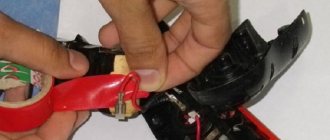
When a cable is broken or hidden, the integrity of the power lines is usually compromised. In this case, it is necessary to remove the insulation from the cable break and restore the connection of the wires.
Instructions:
- Cut the cable where it breaks.
- Remove 5-10mm of outer shell from each edge.
- Remove 3-5 mm of insulation from live wires.
- Reconnect the broken power lines.
- Insulate exposed contacts with insulating tape or heat shrink tubing.
- Fix the break location.
- How to fix a connector
In chargers with a removable cord, in rare cases the cable connector fails. The most common causes of failure are damage to the connector solder, as a result of a hit to the floor or strong shaking. To fix the breakdown, you need to open the case, then solder or replace the connector on the board if the problem is in the connector.
Most charging unit housings are hermetically sealed. Therefore, an engraver with a cutting wheel attachment will help to open the case. You will need to thinly cut the case and remove the control board. And after the repair, solder or seal the case at the cut site.
Car battery charger repair
One of the important parts of the car is the battery - the basis of the electrical equipment of the car. For long and flawless operation of the battery, appropriate care and periodic maintenance are required. When the vehicle is rarely used (for example, in winter), the battery is not used properly. Therefore, to maintain it in working condition, periodic recharging is necessary. A charger is used for this. Like any equipment, this device can break down during use. Then you will have to repair the car charger.
Types of chargers
Today, the industry offers a huge selection of such devices, differing from each other in purpose and design. By design, there are two main types:
Pulse devices contain a current converter. These devices are completely semiconductor. The circuit of such devices is assembled using transistors, thyristors, and triacs. Repairing these is not available to every motorist. This requires a certain level of knowledge in the field of electronics. Such devices have certain advantages: small dimensions and relatively light weight.
In comparison, transformer devices are bulkier and heavier due to the underlying transformer. The circuit of this device is simple. The voltage of the secondary winding of the transformer is rectified using a diode bridge. The current supplied to the battery is adjusted by changing the voltage at the output of the transformer. Such a change can be achieved by switching both the primary and secondary windings of the transformer or using an adjustable variable resistance. The amount of charging current is controlled by an ammeter included in the charger circuit.
According to purpose, two types can be distinguished:
- devices without the ability to start an engine;
- starting charger.
The peculiarity of the second is the presence of powerful electronic parts that can withstand the high current consumed by the starter when starting the engine. In other words, such a ROM can not only charge the battery, but also start the car engine instead of a discharged battery.
Homemade memory
The decision to assemble a homemade battery charger is usually dictated by 2 main reasons:
- there is no money to purchase a factory memory unit, or the motorist simply does not see the point in such expenses;
- there is a desire to try to assemble something similar with your own hands, a sporting or professional interest.
In both cases, there are no significant obstacles to starting to make a homemade charger for car batteries with your own hands.
It is possible to assemble both a simple and a more complex circuit.
The most popular and in demand among car enthusiasts are the following memory devices, assembled on the basis of:
- light bulbs and diodes;
- rectifier
This is a fairly simple, but quite effective charger that is definitely suitable for servicing a car battery. To assemble both units with your own hands, special education or extensive experience is not required.
Light bulb and diode
To be more precise, charging is assembled from a light bulb, as well as from a semiconductor diode.
It is important to use this charger option if the battery is dead and the available charge is not enough to start the engine. This circuit is not the best suited as a permanent charger.
But still, it is precisely due to its quick assembly and ability to start the engine that it has become widespread.
The scheme includes:
- Incandescent lamp. The most ordinary light bulb, approximately 100–150 W, will do.
- Diode. You should take a semiconductor diode. It differs in that it conducts current only in one direction. With its help, alternating voltage will be converted into direct voltage. The diode must withstand a fairly high load.
- A plug that connects the charger to an outlet.
- Wires with terminals, so-called alligator clips, to connect to the battery.
The principle of assembling the circuit is as follows:
- connect the light bulb to the positive of the battery and connect a diode into the gap between them, and on the other side connect it to the positive of the plug;
- connect the minus to the plug;
- isolate all connections and contacts;
- plug the charger into a power outlet.
Provided that a 100 W bulb is used, the charging current will be approximately 0.17 A. That is, it will take about 10 hours to charge the battery.
It is important to consider that such a charger can only recharge slightly dead batteries, which themselves are not able to start the engine. If the battery is deeply discharged, this circuit will not work.
Rectifier
Another example of a simple memory. The charger in question, intended for batteries, consists mainly of a rectifier.
There are 2 main components of the circuit. This is the rectifier itself, as well as a voltage converter.
For charging, you can use 3 types of rectifiers. They can charge using current:
- variable;
- permanent;
- asymmetrical.
Among all these options, the last one seems to be the most preferable.
To assemble the charger, you will need an appropriate rectifier option and a good current amplifier.
Structurally, the rectifier consists of:
- fuse;
- powerful diode;
- zener diode;
- switch;
- variable resistor.
It is not difficult to assemble the circuit.
The assembly involves following these recommendations:
- prepare a fuse of the required rating;
- find a transformer with a power of up to 150 W with an output voltage of about 21 V;
- find a suitable resistor type MLT 2;
- take a rectifier designed for a current of at least 5 A;
- the amplifier can be assembled from 2 transistors of the KT825 type;
- To improve cooling, transistors are installed on radiators during installation.
Assembly is carried out using the hinged method. That is, you need an old board, previously cleared of tracks. All components are placed on it and connected by wires.
The main advantage of the circuit under consideration is the ability to adjust the parameters of the output current for charging power supplies. But there is also a minus. This is the need to search for all the components, as well as increased requirements for the quality and accuracy of their installation and connection to each other.
This scheme has a simplified analogue. It uses a rectifier, a transformer, and a 12 V and 40 W light bulb. The essence of the circuit is to connect the rectifier and the paw to the negative terminal of the battery, connecting them to the transformer. And the plus from the transformer goes directly to the positive terminal of the battery.
Disassembly and testing of the device
Like any equipment, malfunctions may occur in the operation of the charger. Suddenly it turned out that it stopped performing its charging functions. There can be many reasons that led to the malfunction. For example: improper operation, careless storage, aging of parts and wires. Given the complexity of the device, repairing it without appropriate qualifications is only possible superficially. The check is done in the direction from the power source to the battery.
Inspections and repairs are carried out only with equipment disconnected from the network . Using a screwdriver and keys, you need to disassemble the case and inspect the parts of the charger. It is likely that there will be obvious signs of burnt out wires, diodes, and a step-down transformer. Burnout of the windings of the latter is usually accompanied by the release of a pungent odor of burning and soot. It is possible that during inspection a wiring or broken wires will be discovered. If nothing could be detected visually, you need to proceed with a more detailed check.
Recommendations
What to do if the phone takes a long time to charge? We have compiled a list of recommendations for extending battery life for Android and iOS:
- Do not allow the phone to fall by any means. Do not place it on lightweight structures and use covers or protective glass whenever possible.
- Do not allow the battery to be completely discharged. Connect the device to the charging adapter for 15-20% battery.
- Lighten the load on the phone's processor and RAM. To do this, you can remove unnecessary files and applications.
- Use antivirus software.
- Keep your phone at room temperature and avoid extreme low or high temperatures.
Malfunctions and methods for their elimination
After making sure that there is voltage in the socket for connection, you need to check the integrity of the plug and supply wires.
This can be done using the simplest tester. The next step is to check the transformer windings (both primary and secondary), and the fuse used in the circuit for protection. If the transformer is in good condition, plug it into the network and measure the voltage at the transformer output. It should be 14-14.5 Volts. If the voltage is less or the device detects changes, the device is faulty. The next step is to check the transformer winding switch and diode bridge. The latter consists of 4 diodes assembled in a certain way. In order to check the serviceability of each of them, you will have to disassemble the bridge circuit. A diode is a semiconductor that allows current to flow in only one direction. It is checked with a multimeter, changing the polarity. Possible diode malfunctions:
- breakdown (during continuity, current passes in both directions);
- break (does not ring in any direction).
If there are faulty diodes, they must be replaced with new ones. The final step is to check the conductors connected to the battery and the clamps. All faulty parts are replaced, broken conductors are repaired by soldering or twisting. After completing all repair work, you need to assemble the charger casing and perform a final test with a multimeter. The constant voltage on the wires connected to the battery should be 14-14.4 volts. If the charger is working normally, but the battery is not charging (the ammeter shows 0 amps), then the problem is in the battery. It should be checked in detail and replaced if necessary.
Troubleshooting
To find out what to do if the phone does not charge from the charger, the first thing you need to do is diagnose the device for mechanical damage. To do this, you need to check the USB port through which the smartphone is charged.
Instructions for checking the USB port:
- Conduct a visual inspection for the presence of dust or dirt around, inside the port. It is recommended to use a toothpick as well as a needle.
- Check the stability of the port socket. If the connector has play or is slightly loose, then the help of a specialist is needed.
- Check the connector for water or other deposits. Typically, in this case, the USB port changes color to white or slightly blackened.
- Inspect the socket and check for deformed contacts. If they are bent, then you need to contact a service center.
If none of the above problems are found, then you need to check the device’s battery.
Instructions for checking the battery:
- Visual inspection of battery dimensions. If it is deformed and swelling is visible, then the battery is faulty.
- If the battery cannot charge to 99%, then it needs to be replaced.
- Charge using a working adapter. If the smartphone does not detect the battery, but the charging process is ongoing, then it is necessary to replace the battery.
- Check the remaining battery capacity using special applications. They can be downloaded for free from the Play Market and App Store.
If there are no problems with the battery, the reason for slow charging is the high load on the phone's processor or the presence of a virus program. Then you can fix the problem by uninstalling applications and installing an antivirus.