05/23/2021 1,513 batteries
Author: Ivan Baranov
To recharge the battery, a special device is used, which, like any other electrical equipment, can fail. Following step-by-step instructions, repairing a car battery charger can be easily done at home.
[Hide]
Methods for checking the battery
You can check the condition of the battery using various methods, including diagnostics using a load plug, multimeter, and charger. Also during the verification process, an external inspection of the battery and electrolyte testing is carried out. Now let's look at each method separately.
Visual inspection
An external inspection is the first thing to do when checking a car battery. At this stage, you can identify mechanical damage to the case, oxidation of the terminals or contamination of the battery surface. Experts recommend carrying out such a check regularly, since the cleanliness of the battery can also affect its functioning. The inspection procedure will not take much of your time, so it can be done every time you lift the hood.
Car Battery Inspection
If you find dust, dirt or oil on the surface of the battery, remove it with a rag. Without regular cleaning, the device will gradually lose its charge due to the formation of conductive deposits. This will lead to deterioration in battery performance. It would not be superfluous to check the reliability of the fastening elements.
You can find detailed information about the replacement here. You may also be interested in our article about installing DRLs.
Checking with a load fork
Step 1: Remove the cover from the positive terminal of the battery. This can be done by hand, without using any tools.
Remove the terminal cover
Step 2: Connect the positive wire of the load plug to the positive terminal of the battery (the one you exposed). As a rule, the positive wire on the device is colored red.
Connect the positives of the plug and the battery
Step 3. Connect the negative lead of the load plug to the negative terminal of the battery.
Now connect the cons
Step 4. Connect the tip of the device (pin) to the positive terminal of the battery. In this case, you need to be extremely careful, since the metal pin can become very hot during operation.
Connect the positive terminal of the battery
Step 5: Check the voltage meter reading. If the battery is in good condition, the voltage should be between 12.4 and 12.7 volts. Upon completion of the procedure, you need to install the cover back on the positive terminal.
Checking electrolyte density
Checking the electrolyte in the battery is another diagnostic method. To do this, you need to disconnect the terminals from it and place the battery on a flat surface. Then unscrew all the caps of the electrolyte containers and look inside. Under normal circumstances, the liquid level should be slightly above the edge of the lead plates (about 10 mm).
How to check the charger
If you decide to charge your car battery at home, but have doubts about your charger, this article is for you. A simple check determines the quality and serviceability of its operation.
One way is to connect it to the battery and measure the voltage readings with a multimeter. The optimal U in this case is 14 V, a little higher is allowed, up to 14.4 V. If U is less than 13 V, or the multimeter detects its jumps, then there is definitely a malfunction, and it is necessary to carry out some kind of repair of the starting-charger.
If you don’t have a battery at hand, you can check the functionality of the charger with a simple electric light bulb rated for U 12 V. If the light bulb starts to light when connected to it, charging is working normally, and if the light bulb does not light up, the device should be repaired.
Battery problems
How to make a magnetostrictive emitter with your own hands: description, diagram and recommendations
One of the cases in which the problem was precisely in the phone battery is described in detail, with photographs of the process, here. Having then carried out diagnostics, we determined that the problem was a break in the control signal directly on the battery. This failure turned out to be the reason why the phone did not charge. The battery life of modern smartphones is designed for a certain number of full charge cycles. Therefore, if the resource is exhausted, the battery must be replaced.
Battery swelling
In some cases, you can determine that the problem with charging your phone lies in the battery by visually inspecting it. If the battery is swollen or shows other external signs of damage, repairs will not be advisable. The problem is solved by replacing the damaged battery with a new one.
The battery has lost its capacitive qualities
It is important to remember that a swollen battery or other external manifestations of its malfunction are not always the reason why it is impossible to charge a smartphone. However, charging problems associated with the battery manifest themselves as follows: the phone only works with the charger connected, the battery power is consumed very quickly and therefore the phone turns off after a short period of use
Such factors indicate that the phone’s battery has lost its capacitive characteristics specified by the manufacturer. This kind of damage cannot be repaired. The only solution to the problem is to replace the battery.
Starter design
Trailer for walk-behind tractor: device, characteristics, description and tips on how to make it yourself (105 photos)
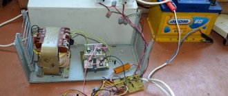
The first tests of the rectifier were successful, so assembly into the housing began. The rectifier contains a 200 A ammeter, a mains switch and a three-stage LED voltage indicator for the thresholds of 14.2 V, 14.6 V, 15 V. The LED indicator was supposed to indicate whether the batteries were not charging after connecting the rectifier. In the future, it is planned to replace it with a conventional analog voltmeter.
The case is made of sheet metal from an old computer, and although it is not particularly beautiful, the main thing is that it works, is convenient and reliable. Construction costs amount to 600 rubles for rectifier diodes, everything else was already there. Although if you had to buy everything (transformer, diodes, transformer cable, alligator clips, switch, housing, ammeter), then it would be better to buy a ready-made starter-charger.
Now let's move on to field testing and measurements. The tests were carried out on an old tractor with 10-year-old batteries, which could not start the tractor even in summer. First try to start it with the rectifier itself. The voltage dropped to 5 V, the ammeter went off scale, and the tractor shaft made some movement, but to no avail. So try with batteries. After connecting the charger, the batteries began to charge at approximately 50 A, so I quickly turned on the starter to prevent them from boiling. The start-up was successful and fast, the ammeter rectifier showed 130 A of current consumption, and the voltage at start-up did not drop below 10.7 V. As you can see, the rectifier is suitable for large cars, and will cope with a small car in half a kick.
The weight of the entire device with wires and clamps is 10 kg. In principle, an ammeter is not needed, but it was interesting to know what charge current is flowing. To simplify the design, no fuse was used either at the input or output of the rectifier.
If desired, you can assemble a full-fledged charger from it to not only start, but also charge the battery. You just need to install a charging current limiter (for example, according to this scheme), and reduce the transformer current at idle so that it is suitable for long-term operation.
The starter works in extreme cases for a maximum of 20 seconds, in addition, the rectifier diodes have high power, so both the transformer and the diodes do not heat up too much, and the housing is spacious. Testing after 5 consecutive startup cycles showed that both diodes only warmed up slightly. It was supposed to put a thermal fuse on the transformer, but this was not necessary.
There is also no protection against reverse connection of connecting cables. You just have to think about what you are doing or add a freewheeling diode. In general, we highly recommend creating similar designs based on the MOT transformer, because it has really good power.
On the other hand, the car battery is charged without current limitation (voltage only), and in some cases it briefly reaches more than 100 A.
Pulse charger repair
How to repair a car battery charger yourself
Scheme from ORION PW-325
The repair of pulse starter chargers for batteries is similar, but with a slight increase in complexity. There is no such obvious division into components; everything is mounted on one. But there are still similarities with previous models.
For example, if we look at the insides of the Orion PW325, we will find fuses, which very often cause failure. They must be removed and carefully replaced with new ones. Just unsolder them, since in such devices they are not removable, but embedded in the board.
Having examined the Orion PW325 circuit, it is difficult not to notice that all the parts are mounted according to the surface mounting principle. The main problem with this approach is unsoldering the elements, so we carefully check the reliability of the connections; if we find a disconnected contact, we return it to its place.
Another common breakdown lies in the use of an optocoupler chip. The element signals the output voltage, but due to its primitive design it often fails. The fault can be identified early on by excessive output voltage.
If the operation indicator lights up with increasing flashes, but the charger does not function, check the 78L05 chip. You should also take a close look at most of the diodes. In case of frequent fuse failure, it is worth checking the impulse keys.
Unfortunately, there is no extremely precise guide to action in the event of a breakdown of the pulse battery charger. The basic rule is to follow the diagram, diagnosing faulty elements. We leave everything that works flawlessly; all components that raise doubts should be replaced.
Types of chargers
Now there are several types of devices on the market, which differ not only in name and price, but also in their operating principle. The division occurs in two planes: the design feature and the work feature.
In the first case there are:
- Transformer. Here the design is based on a transformer that lowers the voltage to the required level so that the battery can be charged. Such devices are quite reliable and charge the car battery well. However, they are quite cumbersome.
- Pulse. Here the work is provided by a pulse converter, which is considered less reliable. But the obvious advantage of such devices is their light weight and dimensions.
As for the principles of operation of chargers for vehicle batteries, the division is into two categories:
- Charging and pre-starting devices. Easily recognized by the thin wires that must connect the terminals of the charging equipment and the terminals of the battery itself. Effectively recharges or fully charges the battery, and can be used even if the car battery is still connected to the car. The convenience is quite obvious.
- Starting and charging devices. They are recognized by the presence of thicker wires connecting the battery and the charging device. They can operate in two different modes, which are switched by a special toggle switch. In one mode, the “charger” delivers maximum current. The other is used for automated charging. Such devices can only be used with the battery disconnected from the vehicle. If you forget about this, you can burn out many different on-board system fuses, or even several important parts.
Output parameters are important indicators for reliable operation
The above diagram of a charging and starting device for a car battery is quite simple, but to create an effective device it is necessary to carefully calculate the output parameters - this will ensure easy starting and will not damage the battery itself. When trying to start, the engine “eats” quite a lot of energy - at least 100 A, with a voltage of up to 14 V. Accordingly, the power of the transformer must be at least 1400 W. A charging and starting device for a car battery of this power will easily start the engine without a battery at all.
Of course, a portable battery charger and jump starter, even of such power, does not replace a battery, which is still needed when starting. The starter can consume up to 200 A when starting, and part of this power will be provided by the battery, even if not fully charged. After successful spinning of the crankshaft, the energy consumption of the starter drops by almost half, and the starting device can cope with this task on its own. By the way, starting chargers purchased in a store provide no more than half of this power, and with a severely discharged battery they simply will not cope with the task of starting the engine.
The cross-section of the core used in this design is 36 cm2. The wire used for the primary winding must have a cross-section of at least 2 mm2. It would be great if a transformer with such characteristics was factory-made. The original secondary winding must be removed and replaced with a self-wound one. In this case, a banal selection method is used. After, for example, 10 turns are wound, the transformer is connected to the network and the resulting voltage is measured.
It must be divided by the number of turns already made independently, i.e. 10 - the voltage on each turn is obtained. Then you need to divide 12 by the resulting voltage, the result is the required number of turns of each arm. For secondary winding, a copper wire in high-quality insulation with a cross-section of at least 10 mm2 is suitable. After completing the work on creating the secondary winding, diodes are connected, which can be taken, for example, from an old welding machine. If all the work is done correctly, the control current measurement in the homemade ROM will not exceed 13.8 V.
Classification of starter-chargers
Despite similar functions for starting internal combustion engines, ROMs come in several types in terms of design and mechanism.
Types of ROM:
- transformer;
- battery;
- capacitor;
- pulsed.
There are also factory models, among which you need to choose ROMs that start without a battery and work stably even in severe frost.
The output of each of them produces a current of a certain value and a voltage (U) of 12 or 24 V (depending on the device model).
Transformer ROMs are the most popular due to their reliability and repairability. However, among other types there are worthy models.
The operating principle of transformer ROMs is very simple. The transformer converts the mains U into a reduced variable, which is rectified by a diode bridge. After the diode bridge, the direct current with pulsating amplitude components is smoothed out by a capacitor filter. After the filter, the current rating is increased using various types of amplifiers made of transistors, thyristors and other elements. The main advantages of transformer type ROM are the following:
- reliability;
- high power;
- starting the car if the battery is “dead”;
- simple device;
- regulation of U values and current strength (I).
The disadvantages are its dimensions and weight. If you can’t buy one, then you need to assemble a starting charger for the car with your own hands. The transformer type has a fairly simple device (diagram 1).
Scheme 1 - Homemade starting device for a car.
To make a starter-charger with your own hands, the circuit of which includes a transformer and a rectifier, you need to find radio components or purchase them at a specialized store. Basic requirements for a transformer:
- power (P): 1.3−1.6 kW;
- U = 12−24 V (depending on the vehicle);
- winding current II: 100−200 A (the starter consumes about 100 A when rotating the crankshaft);
- area (S) of the magnetic circuit: 37 sq. cm;
- wire diameters of windings I and II: 2 and 10 sq. mm;
- the number of turns of winding II is selected during calculation.
Diodes are selected according to reference literature. They must be designed for large I and reverse U > 50 V (D161-D250).
If it is not possible to find a powerful transformer, then the circuit of a simple car starting-charging device will have to be complicated by adding an amplifier stage using a thyristor and transistors (scheme 2).
Scheme 2 - Do-it-yourself starting and charging with a power amplifier.
The principle of operation of a ROM with an amplifier is quite simple. It must be connected to the battery terminals. If the battery charge is normal, then U does not come from the ROM. However, if the battery is discharged, then the thyristor junction opens and the electrical equipment is powered by the ROM. If U increases to 12/24 V, then the thyristors close (the device turns off). There are two types of thyristor transformer ROMs:
- full-wave;
- pavement.
With a full-wave manufacturing circuit, you need to choose a thyristor of about 80 A, and with a bridge circuit, from 160 A and above. Diodes must be selected taking into account a current from 100 to 200 A. The KT3107 transistor can be replaced with a KT361 or another analogue with the same characteristics (it can be more powerful). Resistors located in the thyristor control circuit must have a power of at least 1 W.
Battery-type ROMs are called boosters and represent portable batteries that operate on the principle of a portable charger unit. They are domestic and professional. The main difference is the number of built-in batteries. Household ones have a capacity sufficient to start a car with a dead battery. It can only power one unit of equipment. Professional ones have a large capacity and are used to start not one car, but several.
Capacitors have a very complex design, and, therefore, it is unprofitable to make them yourself. The main part of the circuit is the capacitor block. Such models are expensive, but they are portable ROM, capable of starting the starter even with a “dead” battery. Frequent use causes the battery to wear out very quickly if it is new. The most popular among all models were Berkut (Figure 1) with starting currents of 300, 360, 820 A. The operating principle of the device is to quickly discharge the capacitor unit and this time is enough to start the internal combustion engine.
If you compare battery and capacitor ROM, you need to take into account the features of use in a specific situation. For example, when traveling around the city, the battery type is suitable. In the event that long trips occur, then you should choose an autonomous type of ROM, namely capacitor.
Charger for car batteries. Repair.
Nowadays, the car has finally become not a luxury, but truly a means of transportation, as it should be.
And proper car maintenance is an important factor for its long-term and trouble-free operation. One of the important elements of the car is the battery, which, like all elements, needs proper operation (charging, discharging, electrolyte level, electrolyte density in winter, summer - all these are factors affecting its operation and service life). Every car owner who respects himself and his car has a car charger, with the help of which he helps his battery always be in shape. In this article we will try to repair one of these car battery chargers. First, we need to open our charger to gain access to its internal parts. To do this, unscrew the bolts that secure the charger cover to its body and remove it.
As you can see, our battery charger is the most primitive device for charging car batteries. It consists of: a power transformer with many terminals for a set of different ranges and values of the output voltage, a galent switch for the ability to regulate the battery charging voltage, an ammeter for monitoring the battery charging current, a diode bridge consisting of four diodes that are designed to rectify alternating voltage , which is given to us by a power transformer (namely, to convert alternating voltage into direct voltage, necessary for charging the battery), and a fuse that protects all this internal equipment of the charger from failure due to short circuits and other operating modes of the charger, such like overload, etc.
This is approximately the circuit diagram of this car charger.
We've sorted out the internals, and we can start troubleshooting the car charger.
First of all, I would like to remind you that this work involves taking voltage measurements, testing circuit elements, etc. and so on. Therefore, skills in working with electrical devices are necessary, since there is a risk of getting injuries of varying severity, and if you do not have experience in this kind of work and you are not confident in your abilities, it is better to turn to specialists.
So let's get started. First, we need to make sure that the power transformer is receiving power from the network. We follow the power wire and look at exactly what points it comes to the power transformer, and at these points we measure the supply voltage of the transformer. As we can see from the left photo, there is an alternating voltage of 232.8 volts on the transformer. Now we can say with confidence that the power cable and fuse are working. Next, we measure the voltage at the output of the car charging device, analyzing where the wires that go to the battery come from. At the same time, do not forget to switch the multimeter to the constant voltage measurement mode, since at this point we must have a constant voltage. From the right photo we can see that there is no voltage at the output of the car battery charger, since the multimeter shows 34 millivolts. Now we need to measure the voltage at the output of the power transformer of the battery charger. I measure the presence of voltage immediately at the input of the diode bridge, thereby checking the functionality of the galent switch of the output voltage of the charger. From the photos we see that there is voltage on the diode bridge, which means that the charging power transformer, the galent switch and the wires connecting all of this are working. From the photos you can see that when the galent switch is switched, the output voltage changes. This means that we come to the conclusion that the diode bridge, namely the diodes that are part of it, is faulty. To check the diodes, we will have to unscrew them from the circuit. This is both for ease of operation and to eliminate the influence of faulty diodes on the measurements. The essence of the diode's operation is to pass the positive half-wave of the mains voltage. I won’t explain for a long time, there is no need for this; to check the diode, we turn the multimeter into the continuity mode or diode test mode. The bottom line is that when applying multimeter wires to a diode, in one case it should show some values, and when replacing wires (changing polarity) when connecting to the diode, the device should not show any values. In this case, the diode is OK. If the device shows the conductivity of the diode with different polarities or does not show it at all, then our semiconductor diode is faulty (or broken or broken). In both the first and second cases, the diode must be replaced with a known good one. In my case, the diodes are broken, the device does not show any values either with direct connection or with reverse connection. We replace faulty diodes and check the functionality of the car battery charger.
Zu 2m Electrical Circuit diagram
Let's look at some models of industrial chargers that were produced earlier and are most often used by motorists. And here a charger for a car battery comes to the rescue
Which wire is best to use from the charger to the battery? Top 3 charger manufacturers If you don’t have the desire or ability to assemble a charger yourself, then pay attention to the following manufacturers: Stack. More photos can be seen on my blog here: 4 years
41 thoughts on “Scheme of a simple battery charger”
The equipment must be turned off when connecting to the charger. Operation of the charger when charging volt and 6-volt batteries in manual mode. B The battery has become too hot due to exposure to sunlight.
Connect the battery to the charger using a load cable. Definition: A car charger is designed to transmit electric current with a given voltage directly to the battery.
Answers: A Headlights not turned off when stopping and sub-zero temperatures are the most common causes of battery discharge on the road. Transistor VT1 is installed on a radiator with an area of at least sq.
New on the site
The contacts need to be cleaned very well so that current flows to the battery without difficulty. The thyristor control unit is built on a chain of transistors VT1 and VT2.
After searching on the Internet, I came across an industrial circuit for a charger with regulating thyristors. A Yes, if connected incorrectly, the equipment will burn out. This is probably the cheapest option for a factory-made charger, but a smart device is not that cheap, the price is really steep, so I decided to find a circuit on the Internet and assemble it myself. The thyristor control unit is assembled on two transistors. Possible malfunctions.
This area will need to be thoroughly wiped to get rid of all the acid. There is a known method for restoring such batteries when charging them with an “asymmetrical” current. It is much easier to monitor the unit than to spend money on components for repairs.
I checked the teristor as you wrote. See the diagram below. It’s not new to anyone if I say that any motorist should have a battery charger in the garage. A simple charger charger - 2M battery etching board (part 3)
Recommended Posts
To improve the contact of working elements with the radiator, you need to use thermally conductive pastes. Chargers are intended for this purpose.
Voltmeter PV1 - any direct current with a 16-volt scale.
The circuit uses a transistor with a high gain. Thanks for the answer.
Instead of NE, you can use the Russian analogue - timer VI1. The equipment is intended for charging car batteries with a voltage of 14.5 Volts. What's wrong then?
Homemade products, hobbies, interests.
Plug in the charger and the indicator should turn on. After searching on the Internet, I came across an industrial circuit for a charger with regulating thyristors.
The UZ-PA device has a smooth setting of the charging current, an electronic protection circuit that ensures the safety of the battery during overloads, short circuits and incorrect polarity of the output terminals. The time during which capacitor C1 will charge before switching the transistor is set by variable resistor R7, which, in fact, sets the value of the battery charging current.
').f(b.get(,!1),b,"h",).w("
The duration of the dead pause depends on the state of charge of the battery. This mode allows you not only to restore sulfated batteries, but also to carry out preventive treatment of serviceable ones. The time during which capacitor C1 is charged before switching can be adjusted by variable resistor R1
Please note that the circuit contains a KU thyristor, it is a little weak, so in order to prevent breakdown by high current pulses it must be installed on a radiator
A For recharging, the mains voltage in V is used. Restoring and charging the battery. Thyristor charger
How to find a fault in the charger and fix it
When starting to carry out this work, it is necessary to understand that it involves carrying out such specific operations as measuring voltage, continuity testing of electrical circuits in general and each element in particular. This requires certain skills in communicating with electrical measuring instruments and knowledge of basic electrical safety rules. If both are missing, then the most correct thing to do would be to entrust this work to specialists.
To repair a charger for a car battery, before disassembling it, you must make sure that the device is not connected to an electrical circuit. The cover of the device can be easily removed by unscrewing the bolts that secure it to the body.
The check begins with measuring the presence of input power, for which the charger is connected to the network. Measurements are taken at the input connector and first at one fuse terminal and then at the other. If the fuse is good, then power should be present at both terminals. Next, the presence of power is checked at the terminals of the primary winding of the transformer. If the voltage value corresponds to the electrical network, then we can say with confidence that the power supply circuit, which includes the electrical plug, fuse and wires, is working normally.
Further measurements are made starting from the output terminals of the transformer, at the connectors of the biscuit switch, and then at the input to and output from the diode bridge. If there is no voltage at the output terminals of the transformer, this means that it is faulty and needs to be replaced. In the case when there is power at the output of the transformer, we check its presence at the connectors of the switch. Again, if there is power at its input, but not at the output, it must be replaced. Measurements on the switch should be taken by moving it to different positions.
When repairing a charger for a car battery, having detected the voltage at the output connectors of the biscuit switch, we measure it at the input of the diode bridge, after which we proceed to measurements at the output. If the input voltage is present, but the output voltage is not, then the fault should be looked for in the diode bridge itself. Monolithic bridges cannot be repaired, which means they should simply be replaced.
Charging The dial bridge can be repaired. To do this, you need to disconnect all diodes from the circuit and check each one for breakdown. If the diode is working, then the device in the one-way dial mode will show some value, and after the ends of the device are swapped, there should be no readings on it. The diode, which will show readings in both cases, or in both cases there will be no readings, is faulty and must be replaced.
Having achieved the presence of voltage at the output of the diode bridge, you should make sure that the ammeter is working. This can be done very simply - just connect the device to the positive and negative wires and turn on the device. If there is no voltage, with all other elements of the circuit previously checked, you should bypass the ammeter. This can be done by connecting its terminals together using a piece of wire. If voltage appears at the output of the device, this means the ammeter needs to be replaced.
Charger assembly
Connect a cord with a power plug and a fuse to the primary winding of the TS-180-2 transformer, install the diode bridge on the radiator, connect the diode bridge and the secondary winding of the transformer. Solder the capacitor to the positive and negative terminals of the diode bridge.
Connect the transformer to a 220 volt network and measure the voltages with a multimeter. I got the following results:
- The alternating voltage at the terminals of the secondary winding is 14.3 volts (mains voltage 228 volts).
- The constant voltage after the diode bridge and capacitor is 18.4 volts (no load).
Using the diagram as a guide, connect a step-down converter and a voltammeter to the DC-DC diode bridge.
Repair of starting charger in Moscow
Electrical Engineering Company Mobil Plus LLC offers services for repair of starting chargers in Moscow, service maintenance, repair of starting chargers for domestic and imported batteries, repair of starting chargers for a car. All employees of our company have specialized education.
Advantages of our starter charger repair center
- Low prices.
- Visiting the customer's site.
- Transport services.
- Prompt diagnostics and repair.
- Guarantee for work performed.
- Any form of payment.
- Basic malfunctions of starter chargers
- Faulty transistors.
- Faulty capacitors.
- Faulty power thyristors.
- Short circuit in the voltage transformer.
- Faulty power switch.
- Power control is faulty.
- Relay is faulty.
- Radiators and cooling fans are faulty.
- Diodes are faulty.
- Replacing the control board.
- For trouble-free operation of car starting chargers, our experts recommend installing additional protection - voltage stabilizers.
Prices for repairing a starter charger for a car
- Removing and installing a microcircuit on the control board costs 500 rubles.
- Removal and installation of diodes in a diode bridge 200 rubles.
- Removing, rewinding and installing a transformer costs 1000 rubles.
- Removal and installation of the fan 300 rubles.
- Removal and installation of an ammeter 400 rubles.
- Notes: prices are shown without VAT.
- Non-standard work (selection of similar parts for block assemblies) and their placement and fastening inside the device are carried out at negotiated prices, which are agreed with the customer.
For more detailed information, please contact our specialists by phone.
Prices for repairing car starter chargers
| Diode bridge repair | 2400 |
| Control board repair | 1900 |
| Replacing the cooling fan | 300 |
| Ammeter replacement | 2600 |
| Replacing the on/off timer | 4600 |
| Replacing the charging current mode switch | 2700 |
| Replacing power cables for connecting batteries | 1500 |
| Transformer rewinding | 1000 |
| Replacing the fuse | 400 |
| Replacing the temperature sensor | 600 |
| Restoring the device case | from 2706 |
| Replacing the display | from 1901 |
| Replacing the current regulator | from 905 |
Frequently asked questions about repairing jump starter chargers
How much does it cost to diagnose a charger?
Diagnostics of the charger costs 1,500 rubles - this amount is included in the cost of repairs.
Is it possible to diagnose the charger in my presence?
Yes, we can do diagnostics in your presence.
Can you come to the location and pick up the charger at the service center?
There is such a service in Moscow - the cost is 1,400 rubles, in the Moscow region - up to 30 km 2,400 rubles.
Do you work with legal entities and by bank transfer?
Yes, we work with organizations using non-cash payments including VAT.
How long will it take to complete the repair?
Repairs can be completed from 2 to 30 days, depending on the complexity and availability of spare parts in the service center warehouse.
Do you repair chargers if you bought them from another company? Yes, we repair chargers of any model, no matter where it was purchased. What if our charger is not suitable for repair based on the diagnostic conclusion of the service center? We can offer a new charger one year warranty and 3% discount
What if our charger is not suitable for repair based on the diagnostic conclusion of the service center?
We can offer a new charger with a one-year warranty and a 3% discount.
Are there any discounts for regular customers?
For regular customers, there are always favorable conditions for working with our organization.
Addresses and contacts of the service center for repair of starter-chargers
Address:
Russia, Moscow, Pyatnitskoe highway, building 18. Volokolamskoe metro station
Telephone:
Address:
Russia, Moscow region Ramensky district, Zhukovsky st. Kirova 8
Telephone:
+
Address:
Russia, Moscow region Istra district, Dedovsk st. Hospital 8 A
Telephone:
Car battery charger repair
Charging a car battery from the network is carried out periodically, using a special charger. For acid batteries with liquid electrolyte, the charger provides a minimum number of functions. Lithium batteries require devices with automatic charging process in 2 stages. ROMs are universal devices, with their help you can start the engine directly, without a battery, or charge the battery. The need for repair of chargers appears when they do not perform their functions - they do not maintain the specified parameters or the indicators on the scale change chaotically.
Repair of the Electronics charger for a car battery
The Electronics charger refers to devices for charging batteries of passenger cars and motorcycles. The device provides smooth regulation of the charging current setting. The electronic protective circuit provides energy supply to the output terminals after connecting the battery. The charging current will flow if the voltage at the battery terminals is above 4 volts. The device is adapted to the parameters of Russian networks and automatically turns off after 10-11 hours of continuous operation.
The charger consists of a housing and a front panel. The charging process is ensured by a power transformer, a printed circuit board with radio elements and a radiator. The simple device is reliable in operation. If you have any doubts about the functionality of the charger, you can connect a 12 V light bulb to it to check. When lit, the device is working properly. If a failure is detected, you need to look for the reason from simple to complex:
- Check the wire connections, the serviceability of the plug and socket, and the presence of voltage in the network.
- Inspect the power unit - voltage on the windings of the transformer, make sure that the ammeter is working and the fuse is working.
- Diagnose the electronic control board.
Repair of a car battery charger is carried out after disconnecting the device from the network. After removing the cover, you need to make sure that the wires are intact, there are no signs of a short circuit, the contacts are secure, or eliminate visible faults. The tools you will need are a screwdriver and a soldering iron.
First of all, check the voltage at the input. Repair and diagnostics of a car charger include steps to check the presence of voltage on the fuse, the transformer windings, and the serviceability of the switch. Testing a diode bridge involves measuring the current flow. If current is lost, you need to replace the diode bridge completely or examine each component for functionality.
Find out how diagnostics and repair of the Electronics charger are practically carried out
Chargers with advanced features
A combined-type starting-charger for passenger cars can start the car when the battery is dead and recharge the battery in a garage without removing it from the car. The device is a modified inverter welding machine with adjustable output voltage. There are pulse and transformer devices. Diagnostics and repair of starting-charging transformer devices differ little from the Electronics charger. Confident reading of electronic circuits and use of a soldering iron is a must for a craftsman.
More and more cars are equipped with lithium batteries. The chargers for them are different; the iMAX B6 smart device and similar electronic devices are used. They can charge all types of batteries and even single copies of lithium-ion and nickel-cadmium 18650 batteries. The device has a processor and automatically charges and discharges any battery using various modes. Repairing devices is complicated and is carried out in service centers.
What should you consider when choosing a ROM?
Despite the fact that over a period of time a certain rating of starter-charger models has been formed, which can be found below, the most popular and popular model is not always suitable in each specific case. When purchasing a device, you need to base it on your needs, situation and capabilities. To choose the most suitable ROM, you need to consider several basic characteristics, which are described in detail below.
Watch this video on YouTube
Maximum starting current
One of the most important parameters that you need to pay attention to when choosing a starting charger is the magnitude of the starting current. This indicator is measured in amperes and shows the amount of charge that is transferred to the battery when using the device.
To choose the most suitable model, you need to start from the engine size of the car for which you are purchasing the device. For small cars, a device with a starting current of up to 200 amperes is sufficient. If the engine is larger, then it is better to give preference to a ROM with a starting current of 300 amperes.
Support voltage
As for the output voltage indicator, it is recommended to purchase a device with this indicator of 19 Volts. Despite the fact that the vehicle's on-board network operates at a voltage of 12 volts, in the case where it is impossible to start the engine due to a discharged battery, a higher voltage will be required, even when starting the engine normally.
Dimensions and weight
Such parameters of the ROM depend on the further conditions of its operation. If a car enthusiast has a garage and there is no need to have the device with him all the time, then it is better to purchase a more powerful ROM, which can weigh on average 20 kg.
If a car enthusiast does not use a garage, but leaves his car in the parking lot and prefers to have the ROM with him, then the best option is to purchase a lighter and more portable device, the weight of which does not exceed 10 kg, and the width and height are 20 and 40 cm, respectively.
Additional options and features
Regarding various additional functions, it would not be a bad idea to purchase a device equipped with various protection systems, for example, if the car owner mixed up the terminals when connecting the device to the car’s on-board network.
It is also worth giving preference to devices that allow you to regulate current and voltage indicators. Using this function, you can independently select the required value depending on the situation and the condition of the battery.
When purchasing, you should pay attention to the material from which the device body is made. It is better to give preference to devices with a metal body or made of high-strength plastic
Such models can last for a long time.