A simple current stabilizer charger made from scrap materials
There are a huge number of ready-made circuits and designs that allow you to charge a car battery. This article is on the topic of converting a computer power supply to an automatic car battery charger. It tells how to assemble an automatic current stabilizer with the ability to adjust the output current.
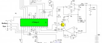
The stabilizer circuit used in our assembled charger is quite simple and is based on an open-loop operational amplifier (OP-amp) with a high gain.
The LM358 microcircuit is used as such an operational amplifier, or it would be more correct to call it a comparator. The image shows that it has:
- two inputs (inverting and non-inverting);
- one exit.
The job of the LM358 is to balance the output by increasing or decreasing the voltage at the inputs.
A charger or simple stabilizer is a device that:
- smoothes out network ripples;
- maintains a straight line of the current graph at the same level.
How is this done? In our case, a reference voltage is supplied to one input, set using a zener diode. The second input is connected after the shunt, intended to act as a current sensor. When a discharged battery is connected to the output, the current in the circuit increases and, accordingly, a voltage drop occurs across the low-resistance resistor. On the LM358 chip, a voltage difference appears between the two inputs. The device seeks to balance this difference, thereby increasing the output parameters.
Read also: DIY devices for cutting logs with a chainsaw
Looking at the diagram, we see that a field-effect transistor is connected to the output, which controls the load. As the battery charges, the voltage at the terminals of the device begins to increase, therefore, it begins to increase at one of the inputs of the op-amp. A voltage difference arises between the inputs, which the op-amp tries to equalize by reducing the output voltage, thereby reducing the current in the main circuit.
As a result, the battery is charged to the required voltage, that is, the set value at the charger terminals. The voltage drop across resistor R3 becomes minimal or will not exist at all. When the voltage at the inputs is equalized, the transistor closes, thereby disconnecting the load from the charger.
A feature of this circuit is that it allows you to limit the charge current. This is done using a variable resistor, which is connected in series to the divider. And by actually turning the knob of this resistor, you can change the parameters at one of the inputs. The resulting difference is again equalized by increasing or decreasing the parameters.
There are no universal schemes. Someone is interested in the issue of increasing the load current. For example, what needs to be changed in the circuit for 15 A? It will be necessary to install a variable not 5, but 10 kOhm. By also making a preliminary calculation and replacing the corresponding elements, you can easily customize the circuit to suit your needs.
About Charger Parts
Power transformer T1 is used type TN61-220, the secondary windings of which are connected in series, as shown in the diagram. Since the efficiency of the charger is at least 0.8 and the charging current usually does not exceed 6 A, any transformer with a power of 150 watts will do. The secondary winding of the transformer should provide a voltage of 18-20 V at a load current of up to 8 A. If there is no ready-made transformer, then you can take any suitable power and rewind the secondary winding. You can calculate the number of turns of the secondary winding of a transformer using a special calculator.
Capacitors C4-C9 type MBGCh for a voltage of at least 350 V. You can use capacitors of any type designed to operate in alternating current circuits.
Diodes VD2-VD5 are suitable for any type, rated for a current of 10 A. VD7, VD11 - any pulsed silicon ones. VD6, VD8, VD10, VD5, VD12 and VD13 are any that can withstand a current of 1 A. LED VD1 is any, VD9 I used type KIPD29. A distinctive feature of this LED is that it changes color when the connection polarity is changed. To switch it, contacts K1.2 of relay P1 are used. When charging with the main current, the LED lights up yellow, and when switching to the battery charging mode, it lights up green. Instead of a binary LED, you can install any two single-color LEDs by connecting them according to the diagram below.
The operational amplifier chosen is KR1005UD1, an analogue of the foreign AN6551. Such amplifiers were used in the sound and video unit of the VM-12 video recorder. The good thing about the amplifier is that it does not require two-polar power supply or correction circuits and remains operational at a supply voltage of 5 to 12 V. It can be replaced with almost any similar one. For example, LM358, LM258, LM158 are good for replacing microcircuits, but their pin numbering is different, and you will need to make changes to the printed circuit board design.
Relays P1 and P2 are any for a voltage of 9-12 V and contacts designed for a switching current of 1 A. P3 for a voltage of 9-12 V and a switching current of 10 A, for example RP-21-003. If there are several contact groups in the relay, then it is advisable to solder them in parallel.
Switch S1 of any type, designed to operate at a voltage of 250 V and having a sufficient number of switching contacts. If you don’t need a current regulation step of 1 A, then you can install several toggle switches and set the charging current, say, 5 A and 8 A. If you charge only car batteries, then this solution is completely justified. Switch S2 is used to disable the charge level control system. If the battery is charged with a high current, the system may operate before the battery is fully charged. In this case, you can turn off the system and continue charging manually.
Any electromagnetic head for a current and voltage meter is suitable, with a total deviation current of 100 μA, for example type M24. If there is no need to measure voltage, but only current, then you can install a ready-made ammeter designed for a maximum constant measuring current of 10 A, and monitor the voltage with an external dial tester or multimeter by connecting them to the battery contacts.
Assembling the device
Of course, it’s interesting to look at the finished homemade product, then let’s start assembling the device. There are many compact boards for this design in online stores. The cost of parts for assembling this voltage stabilizer will cost less than two hundred rubles. If you buy a ready-made voltage stabilizer, you will have to pay several times more.
We will not describe all standard assembly actions; we will only note the main points. The transistor must be placed on a heat sink. Why? Because the circuit is linear and at high currents the transistor will get very hot. What is the radiator made of? It can be made from a regular aluminum corner and attached directly to the power supply fan. And, despite the fact that the radiator is quite small in size, thanks to the intense airflow it will cope with its task perfectly.
A transistor is screwed to the radiator through thermal paste; in this circuit it uses a field-effect, N-channel IRFZ44 with a maximum current of 49 A. Since the radiator is isolated from the main board and case, the transistor is screwed directly without insulating spacers.
The stabilizer board is fixed to the same aluminum corner through a brass stand. To regulate the output current, a 5 kOhm variable resistor is used. The wires are secured with plastic ties to prevent them from dangling.
As a result, you should get the following connection diagram for this stabilizer for the charger.
The power supply can be absolutely anything, either a computer power supply or a regular transformer. The cord used to connect to the outlet is a regular computer one.
All is ready. You can now use such an adjustable voltage stabilizer for the charger. It should be noted that the circuit is simple and inexpensive: it simultaneously functions as a stabilizer and a charger.
Remaking a laptop charger
However, you can do without searching for a transformer if you have an unnecessary laptop charger at hand - with a simple modification we will get a compact and lightweight switching power supply capable of charging car batteries. Since we need to get an output voltage of 14.1-14.3 V, no ready-made power supply will work, but the conversion is simple. Let's look at a section of a typical circuit according to which devices of this kind are assembled:
In them, maintaining a stabilized voltage is carried out by a circuit from the TL431 microcircuit that controls the optocoupler (not shown in the diagram): as soon as the output voltage exceeds the value set by resistors R13 and R12, the microcircuit lights up the optocoupler LED, tells the PWM controller of the converter a signal to reduce the duty cycle of the supplied to the pulse transformer. Difficult? In fact, everything is easy to do with your own hands.
Having opened the charger, we find not far from the output connector TL431 and two resistors connected to the Ref. It is more convenient to adjust the upper arm of the divider (resistor R13 in the diagram): by decreasing the resistance, we reduce the voltage at the output of the charger; by increasing it, we raise it. If we have a 12 V charger, we will need a resistor with a higher resistance, if the charger is 19 V, then with a smaller one.
Video: Charging for car batteries. Protection against short circuit and reverse polarity. With your own hands
We unsolder the resistor and instead install a trimmer, pre-set on the multimeter to the same resistance. Then, having connected a load (a light bulb from a headlight) to the output of the charger, we turn it on to the network and smoothly rotate the trimmer motor, while simultaneously controlling the voltage. As soon as we get the voltage within 14.1-14.3 V, we disconnect the charger from the network, fix the trimmer resistor slide with nail polish (at least for nails) and put the case back together. It will take no more time than you spent reading this article.
There are also more complex stabilization schemes, and they can already be found in Chinese blocks. For example, here the optocoupler is controlled by the TEA1761 chip:
However, the setting principle is the same: the resistance of the resistor soldered between the positive output of the power supply and the 6th leg of the microcircuit changes. In the diagram shown, two parallel resistors are used for this (thus obtaining a resistance that is outside the standard series). We also need to solder a trimmer instead and adjust the output to the desired voltage. Here is an example of one of these boards:
By checking, we can understand that we are interested in the single resistor R32 on this board (circled in red) - we need to solder it.
There are often similar recommendations on the Internet on how to make a homemade charger from a computer power supply. But keep in mind that all of them are essentially reprints of old articles from the early 2000s, and such recommendations are not applicable to more or less modern power supplies. In them it is no longer possible to simply raise the 12 V voltage to the required value, since other output voltages are also controlled, and they will inevitably “float away” with such a setting, and the power supply protection will work. You can use laptop chargers that produce a single output voltage; they are much more convenient for conversion.
Analysis of more than 11 circuits for making a charger with your own hands at home, new circuits for 2021 and 2021, how to assemble a circuit diagram in an hour.
- What are the main reasons why a car battery discharges on the road?
A) The motorist got out of the vehicle and forgot to turn off the headlights.
B) The battery has become too hot due to exposure to sunlight.
- Can the battery fail if the car is not used for a long time (sitting in a garage without starting)?
A) If left idle for a long time, the battery will fail.
B) No, the battery will not deteriorate, it will only need to be charged and it will function again.
- What current source is used to recharge the battery?
A) There is only one option - a network with a voltage of 220 volts.
B) 180 Volt network.
- Is it necessary to remove the battery when connecting a homemade device?
A) It is advisable to remove the battery from its installed location, otherwise there is a risk of damaging the electronics due to high voltage.
B) It is not necessary to remove the battery from its installed location.
- If you confuse “minus” and “plus” when connecting a charger, will the battery fail?
A) Yes, if connected incorrectly, the equipment will burn out.
B) The charger simply will not turn on; you will need to move the necessary contacts to the correct places.
Answers:
- A) Headlights not turned off when stopping and sub-zero temperatures are the most common causes of battery discharge on the road.
- A) The battery fails if it is not recharged for a long time when the car is idle.
- A) For recharging, a mains voltage of 220 V is used.
- A) It is not advisable to charge the battery with a homemade device if it is not removed from the car.
- A) The terminals should not be mixed up, otherwise the homemade device will burn out.
Vehicle batteries require periodic charging. The reasons for the discharge can be different - from headlights that the owner forgot to turn off, to negative temperatures outside in winter. To recharge the battery you will need a good charger. This device is available in large varieties in auto parts stores. But if there is no opportunity or desire to purchase, then you can make the charger yourself at home. There are also a large number of schemes - it is advisable to study them all in order to choose the most suitable option.
Definition:
A car charger is designed to transmit electric current with a given voltage directly to the battery.
Review of car battery charger circuits
Compliance with the operating mode of rechargeable batteries, and in particular the charging mode, guarantees their trouble-free operation throughout their entire service life.
The batteries are charged with a current, the value of which can be determined by the formula I = 0.1Q
where I is the average charging current, A., and Q is the nameplate electric capacity of the battery, Ah.
The charging current recommended in the battery operating instructions ensures optimal electrochemical processes in the battery and normal operation for a long time.
The classic circuit of a car battery charger consists of a step-down transformer, a rectifier and a charging current regulator. Wire rheostats (see Fig. 1) and transistor current stabilizers are used as current regulators.
In both cases, these elements generate significant thermal power, which reduces the efficiency of the charger and increases the likelihood of its failure.
To regulate the charging current, you can use a store of capacitors connected in series with the primary (mains) winding of the transformer and acting as reactances that dampen excess network voltage. A simplified diagram of such a device is shown in Fig. 2.
In this circuit, thermal (active) power is released only on the diodes VD1-VD4 of the rectifier bridge and the transformer, so the heating of the device is insignificant.
The disadvantage of the circuit in Fig. 2 is the need to provide a voltage on the secondary winding of the transformer one and a half times greater than the rated load voltage (
The charger circuit, which provides charging of 12-volt batteries with a current of up to 15 A, and the charging current can be changed from 1 to 15 A in steps of 1 A, is shown in Fig. 3.
It is possible to automatically turn off the device when the battery is fully charged. It is not afraid of short-term short circuits in the load circuit and breaks in it.
Switches Q1 - Q4 can be used to connect various combinations of capacitors and thereby regulate the charging current.
The variable resistor R4 sets the operating threshold of relay K2, which should operate when the voltage at the battery terminals is equal to the voltage of a fully charged battery.
In Fig. Figure 4 shows a diagram of another charger in which the charging current is smoothly regulated from zero to the maximum value.
The change in current in the load is achieved by adjusting the opening angle of the thyristor VS1. The control unit is made on a unijunction transistor VT1. The value of this current is determined by the position of the variable resistor R5. The maximum battery charging current is 10A, set with an ammeter. The device is protected on the mains and load side by fuses F1 and F2.
A version of the charger printed circuit board (see Fig. 4), 60x75 mm in size, is shown in the following figure:
In the diagram in Fig. 4, the secondary winding of the transformer must be designed for a current three times greater than the charging current, and accordingly, the power of the transformer must also be three times greater than the power consumed by the battery.
This circumstance is a significant drawback of chargers with a current regulator thyristor (thyristor).
The rectifier bridge diodes VD1-VD4 and the thyristor VS1 must be installed on radiators.
It is possible to significantly reduce power losses in the SCR, and therefore increase the efficiency of the charger, if the control element is moved from the circuit of the secondary winding of the transformer to the circuit of the primary winding. The diagram of such a device is shown in Fig. 5.
In the diagram in Fig. 5 control unit is similar to that used in the previous version of the device. SCR VS1 is included in the diagonal of the rectifier bridge VD1 - VD4. Since the current of the primary winding of the transformer is approximately 10 times less than the charging current, relatively little thermal power is released on the diodes VD1-VD4 and the thyristor VS1 and they do not require installation on radiators. In addition, the use of an SCR in the primary winding circuit of the transformer made it possible to slightly improve the shape of the charging current curve and reduce the value of the current curve shape coefficient (which also leads to an increase in the efficiency of the charger). The disadvantage of this charger is the galvanic connection with the network of elements of the control unit, which must be taken into account when developing a design (for example, use a variable resistor with a plastic axis).
A version of the printed circuit board of the charger in Figure 5, measuring 60x75 mm, is shown in the figure below:
The rectifier bridge diodes VD5-VD8 must be installed on radiators.
In the charger in Figure 5 there is a diode bridge VD1-VD4 type KTs402 or KTs405 with the letters A, B, C. Zener diode VD3 type KS518, KS522, KS524, or made up of two identical zener diodes with a total stabilization voltage of 16÷24 volts (KS482, D808 , KS510, etc.). Transistor VT1 is unijunction, type KT117A, B, V, G. The diode bridge VD5-VD8 is made up of diodes with an operating current of at least 10 amperes (D242÷D247, etc.). The diodes are installed on radiators with an area of at least 200 sq.cm, and if the radiators become very hot, a fan can be installed in the charger case for ventilation.
Source
Charging the battery from the computer power supply
To charge any battery, 5-6 ampere hours is enough, this is about 10% of the capacity of the entire battery. Any power supply with a capacity of 150 W or more can produce it.
So, let's look at 2 ways to make your own charger from a computer power supply.
Method one
For manufacturing you need the following parts:
- power supply, power from 150 W;
- resistor 27 kOhm;
- current regulator R10 or resistor block;
- wires from 1 meter long with terminals;
Work progress:
- First we need to disassemble the power supply.
- We remove the wires we are not using, namely -5v, +5v, -12v and +12v.
- We replace resistor R1 with a pre-prepared 27 kOhm resistor.
- We remove wires 14 and 15, and simply disconnect 16.
- From the unit we take out the power cord and wires to the battery.
- Install the current regulator R10. In the absence of such a regulator, you can make a homemade resistor block. It will consist of two 5 W resistors, which will be connected in parallel.
- To configure the charger, install a variable resistor in the board.
- to outputs 1,14,15,16 , and use a resistor to set the voltage to 13.8-14.5V.
- to the ends of the wires .
- We delete the remaining unnecessary tracks.
Method two
To manufacture our device using this method, you will need a slightly more powerful power supply, namely 350 W. Since it can output 12-14 amps which will satisfy our needs.
Work progress:
- In computer power supplies, the pulse transformer has several windings, one of them is 12V, and the second is 5V. To make our device, you only need a 12V winding.
- To start our unit you will need to find the green wire and connect it to the black wire. If you use a cheap Chinese unit, there may be a gray wire instead of a green one.
- If you have an old-style power supply with a power button, the above procedure is not necessary.
- Next , we make 2 thick busbars from the yellow and black wires, and cut off the unnecessary wires. A black tire will be a minus, a yellow one will be a plus.
- To increase the reliability of our device, we can swap diodes. The fact is that the 5V bus has a more powerful diode than the 12V.
- Since the power supply has a built-in fan , it is not afraid of overheating.
Method three
For manufacturing we will need the following parts:
- power supply, power 230 W;
- board with TL 431 chip;
- resistor 2.7 kOhm;
- resistor 200 Ohm power 2 W;
- 68 Ohm resistor with a power of 0.5 W;
- resistor 0.47 Ohm power 1 W;
- 4-pin relay;
- 2 diodes 1N4007 or similar diodes;
- resistor 1kOhm;
- bright LED;
- wire length of at least 1 meter and cross-section of at least 2.5 mm 2, with terminals;
Work progress:
- We solder all the wires except 4 black and 2 yellow wires, since they supply power.
- Close the contacts responsible for overvoltage protection with a jumper so that our power supply does not turn off due to overvoltage.
- We replace the built-in resistor on the board with the TL 431 chip with a 2.7 kOhm resistor to set the output voltage to 14.4 V.
- We add a 200 Ohm resistor with a power of 2 W to the output from the 12V channel to stabilize the voltage.
- We add a 68 Ohm resistor with a power of 0.5 W to the output from the 5V channel to stabilize the voltage.
- We solder the transistor on the board with the TL 431 chip to eliminate obstacles when setting the voltage.
- We replace the standard resistor in the primary circuit of the transformer winding with a 0.47 Ohm resistor with a power of 1 W.
- We are assembling a protection circuit against incorrect connection to the battery.
- unnecessary parts from the power supply
- We remove the necessary wires from the power supply.
- Solder the terminals to the wires.
The advantage of such a homemade device is the inability to recharge the battery.
Circuit diagram of a simple charger
According to the principle of operation, chargers can be transformer and pulse (electronic). While pulse devices are difficult to assemble on your own and have expensive components, other devices are based on only two components - a transformer and a rectifier. The operating principle of these chargers is to convert the 220 V household voltage into the voltage necessary to charge, for example, 12 volt batteries installed in a passenger car.
You can make a simple transformer battery charger with your own hands using the following options.
Circuit with one rectifying diode
The diode is installed after the transformer. The alternating current rectified with its help presents ripples with a sharp increase to a maximum value. The diagram and graph of the pulsating current are shown in the image:
Circuit with diode bridge
With the help of a diode bridge, the rectified current will remain pulsating, but no sharp beating will occur. This scheme is most often used for amateur creativity. Below in the text, as an example based on it, is a version of the practical implementation of a charger with your own hands.
Circuit with diode bridge and smoothing capacitor
The output is constant current, which is the best option for charging the battery. Despite the fact that charging will be a fairly long process, the operational life of the battery will remain quite long.