In 1845, Gustav Kirchhoff, a physicist from Germany, derived two rules that allow us to consider the correspondence between potential differences and current strength in sections of an electrical circuit. They are also called laws, but these are rather conditions that allow us to create a system of equations. By solving such equations, any most complex electrical circuit can be calculated.
Gustav Robert Kirchhoff - German physicist
Formulation of the rules
Each Kirchhoff rule has universal properties. Both the first and second, although they do not relate to fundamental laws, are firmly substantiated.
Attention! Kirchhoff's rules apply equally to circuits of any kind of current.
Definitions
Before considering the simple principles and meaning of solving CS (systems of equations), you need to decide on the formulations used. In the typology of chains, the following concepts are used:
- branch;
- node;
- circuit.
All these are elements of an electrical circuit (EC).
Elements of EC
The part of an electrical circuit through which electricity of the same magnitude passes is called a branch. The place where three or more branches connect is called a node. Typically, on diagrams, nodes are indicated by large dots. A circuit is the path along which electric current flows, passing through several sections of the EC, including nodes and branches.
Important! Current (I), leaving one point in the circuit and once passing through branches and nodes, must necessarily return to the beginning. A circuit is a closed circuit.
Nodes and branches that are subject to the contour being studied at a certain moment can be part of other contours: they are common to several closed ECs at the same time.
First rule
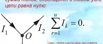
Kirchhoff's first law sounds like this: “The sum of all currents in the EC nodes is equal to zero.” If you give direction to the currents flowing through the intersections of conductors that have a common contact (node), then you can mark the inflowing currents with arrows pointing to the node. It is convenient to mark the flowing currents with arrows directed away from the node:
I1 + I2 – I3 – I4 – I5 = 0
Picture of the direction of movement of electricity
Conventionally assuming that incoming I have a positive sign, and outgoing ones have a negative sign, we can rephrase the statement. According to the law of conservation of charge, the algebraic sums of I entering and leaving a node are equal in value.
First Law
You can verify the truth of the first rule by assembling a mixed circuit for connecting resistors as a load for a power source U = 3 V.
Ammeters included in the branches allow you to visually record the values of currents entering and leaving the first node. Their algebraic sum (taking into account the signs) will be equal to zero.
Circuit diagram with installation of ammeters
Second rule
It is called the voltage rule, it states that the sum of all E (EMF) included in the circuit is equal to the sum of the voltage drops across the resistive elements, provided that the circuit is closed:
ΣE = ΣI*R.
For example, for a circuit with a battery and a resistor, the voltage across the resistor U = I*R will be equal to the emf of the battery. According to Kirchhoff's second definition, the expression will look like:
E = I*R.
Circuit with one EMF and one resistor
By analogy, if the number of resistors is increased, then the voltage drop across them will be distributed so that in total they will be equal to the value of the EMF of the power source:
E = I*R1 + I*R2 + I*R.
Turning on one EMF and three resistors of the same value
The explanation would not be complete if we did not consider a circuit with several EMFs included in the circuit. In this case, equality should be expressed as follows:
E1 + E2 = I*R1 + I*R2 + I*R3.
For your information. When connecting several sources to one circuit, it is necessary to maintain polarity by connecting the plus of one source in series with the minus of another, thus the EMF values will be summed up.
Connecting two sources to a loop
First Law
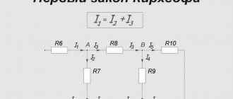
Kirchhoff's first law establishes the relationship between currents for nodes of an electrical circuit to which several branches approach. According to this law, the algebraic sum of the currents of the branches converging at a node of an electrical circuit is equal to zero:
?I = 0 (16)
In this case, currents directed to the node are taken with one sign (for example, positive), and currents directed from the node are taken with the opposite sign (negative). For example, for node A
I1 + I2 + I3 – I4 – I5 = 0 (17)
This is interesting! All about semiconductor diodes.
Transforming this equation, we find that the sum of currents directed to a node in the electrical circuit is equal to the sum of currents directed from this node:
I1 + I2 + I3 = I4 + I5 (17′)
In this case, there is a complete analogy with the distribution of water flows in pipelines connected to each other.
Kirchhoff's laws establish the relationship between currents and voltages in branched electrical circuits of any type. Kirchhoff's laws are of particular importance in electrical engineering because of their versatility, as they are suitable for solving any electrical problems. Kirchhoff's laws are valid for linear and nonlinear circuits at constant and alternating voltages and currents.
Kirchhoff's first law.
Kirchhoff's second law establishes the relationship between e. d.s. and voltage in a closed electrical circuit. According to this law, in any closed contour the algebraic sum e. d.s. equal to the algebraic sum of the voltage drops across the resistances included in this circuit:
?E = ?IR (18)
When drawing up formulas characterizing Kirchhoff's second law, the values of e. d.s. E and voltage drops IR are considered positive if the directions of e. d.s. and currents in the corresponding sections of the circuit coincide with an arbitrarily chosen direction of traversal of the circuit. If the directions e. d.s. and currents in the corresponding sections of the circuit are opposite to the selected direction of bypass, then such e. d.s. and voltage drops are considered negative.
Let us consider, as an example, an electrical circuit in which there are two sources with electromotive forces E1 and E2, internal resistances Ro1, Ro2 and two receivers with resistances R1 and R2. Applying Kirchhoff's second law to “this circuit and choosing the direction of its traversal clockwise,
It will be interesting➡ What is a trigger in electronics - we understand the terms in detail
we get:
E1 – E2 = IR01 + IR02 + IR1 + IR.
At the same time, e. d.s. E1 and current I coincide with the selected direction of bypassing the circuit and are considered positive, and e. d.s. E2, opposite to this direction, is considered negative. If in an electrical circuit e. d.s. sources of electrical energy when bypassing the corresponding circuit are directed towards each other (see Fig. 24, a), then such a connection is called counter-connection. In this case, based on Kirchhoff’s second law, current I = (E1-E2)/(R1+R2+R01+R02).
Counter direction e. d.s. takes place, for example, on e. p.s. when connecting DC electric motors (they can be considered as some sources of emf) in two parallel groups, as well as when connecting batteries in a battery in parallel.
If e. d.s. sources of electrical energy have the same direction along the contour (Fig. 24, b), then such a connection is called consonant and the current I = (E1-E2)/(R1+R2+R01+R02). In some cases, such inclusion is unacceptable, since the current in the circuit increases sharply.
If there are branches in the electrical circuit (Fig. 24, c), then various currents I1 and I2 pass through its individual sections. According to Kirchhoff's second law, E1-E2=I1R01+I1R1-I2R2-I2R02-I2R3+I1R4.
When composing this equation, e. d.s. E1 and current I1 are considered positive, since they coincide with the accepted direction of bypassing the circuit, e. d.s. E2 and current I2 are negative.
Calculations of electrical circuits using Kirchhoff's laws
Rotation speed: formula
To perform such calculations of electrical circuits, there is a certain algorithm in which the currents for each branch and the voltage at the terminals of all elements included in the EC are calculated. In order to calculate any scheme, adhere to the following order:
- The EC is divided into branches, contours and nodes.
- Arrows indicate the expected directions of movement of I in the branches. Arbitrarily mark the direction in which the contour is walked around when writing equations.
- Write equations using Kirchhoff's first and second rules. In this case, the rules of signs are taken into account, namely:
- “plus” are currents flowing into the node, “minus” are currents flowing out of the node;
- E (EMF) and the reduction in voltage across resistors (R*I) are denoted by a “plus” sign if the current and bypass are the same in direction, or “minus” if not.
- By solving the resulting equations, the required values of currents and voltage drops across the resistive elements are found.
Information. Independent nodes are those that differ from others in at least one new branch. Branches containing EMF are called active, while branches without EMF are called passive.
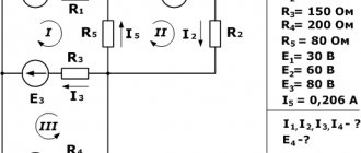
As an example, we can consider a circuit with two EMFs and calculate the currents.
Example of a diagram for calculations with two E
The direction of currents and circuit bypass is arbitrarily chosen.
Intended directions on the diagram
The following equations are compiled using Kirchhoff’s first and second laws:
- I1 – I3 – I4 = 0 – for node a;
- I2 + I4 – I5 = 0 – for node b;
- R1*I1 + R3*I3 = E1 – acef circuit;
- R4*I4 – R2*I2 – R3*I3 = – E2 – circuit abc;
- R6*I5 + R5*I5 + R2*I2 = E2 – bdc circuit.
Equations are solved using determinant or substitution methods. You can also use online calculators.
Second Law
To calculate complex electrical circuits with several energy sources, Kirchhoff’s second law is used, which can be formulated as follows: in any closed electrical circuit, the algebraic sum of all e. d.s. equal to the algebraic sum of the voltage drops in the resistances connected in series to this circuit, i.e.
E1 + E2 + E3 + . . . = I1r1 + I2r2 + I3r3 + . . .
It will be interesting➡ What is grounding in simple words
In this case, e. should be considered positive. d.s. and currents, the direction of which coincides with the direction of bypassing the circuit. If two energy sources are included in an electrical circuit, e.g. d.s. which coincides in direction (Fig. 20, a), then e. d.s. the entire chain is equal to the sum of e. d.s. these sources, i.e. E = E1 + E2. If in the circuit e. d.s. sources have opposite directions, then the resulting e. d.s. equal to the difference e. d.s. these sources, i.e.
E = E1 – E2.
Kirchhoff's second law.
When several energy sources with different directions of e.g. are connected in series to an electrical circuit. d.s. general e. d.s. equal to the algebraic sum e. d.s. all sources. When summing up e. d.s. one direction is taken with a plus sign, and e. d.s. opposite direction - with a minus sign. When composing the equations, the direction of traversal of the circuit is chosen and the directions of the currents are arbitrarily specified.
A closed circuit is designated by the letters a, b, c and d. Due to the presence of branches at points a, b, c, d, the currents I1, I2, I3 and I4, differing in strength, can have different directions. For such a chain, in accordance with Kirchhoff’s second law, we can write:
E1 – E2 – E3 = I1(r01 + r1) – I2(r02 + r2) – I3(r03 + r3) + I4r4,
where r01, r02, r03 are the internal resistances of energy sources, r1, r2, r3, r4 are the resistances of energy receivers. In the special case, in the absence of branches and series connection of conductors, the total resistance is equal to the sum of all resistances. If the external circuit of an energy source with internal resistance r consists, for example, of three series-connected conductors with resistances respectively equal to r1, r2, r3, then based on Kirchhoff’s second law, the following equality can be written:
E = I r + I r1 + I r2 + I r3.
With several current sources on the left side of this equality there would be an algebraic sum e. d.s. these sources.
Kirchhoff's laws for a magnetic circuit
A magnetic circuit (MC), like an electric circuit (EC), can be calculated according to these rules. By analogy with chains, the following connection can be distinguished:
- magnetic flux - electric current;
- MMF (magnetomotive force) – EMF.
The principle of operation of the thermostat
The first rule for the MC is that the magnetic fluxes at the nodes in the algebraic sum give zero (ΣΦк= 0). It is based on the physical principle of continuity Φ.
The second rule says that the drop in magnetic voltage (strength) U m in a closed circuit in an algebraic sum is equal to the sum of the MMF of this circuit:
ΣUм = ΣI*ω, where:
- I – current passing through the conductor;
- ω – number of turns in the winding.
Kirchhoff's second law is a differently written form of the total current law.
Attention! For magnetic circuits, the algorithm for composing equations is the same as for EC.
The rules for signs work similarly.
Verification of Kirchhoff's laws
Laboratory work No. 1.1
OHM'S AND KIRCHHOFF'S LAWS
IN RESISTIVE CIRCUITS.
Goal of the work
:
experimentally verify the validity of Ohm's and Kirchhoff's laws for resistive circuits containing sources of constant voltages and currents.
Learn to measure the voltage and current transfer coefficients of a four-terminal network and study the transfer characteristics of voltage and current dividers. Checking Ohm's Law
In an electrical circuit of any complexity, a number of topological elements can be distinguished. These include: branch, node, contour
.
Branch
- this is a section of a circuit between two nodes, through the elements of which the same current flows.
Knot
- the junction of three or more branches.
Circuit
- any closed section of a chain passing through several branches.
Ohm's law
establishes a relationship between current
I
and voltage
U
in a section of a circuit (branch) with resistance
R
(Fig. 1).
It is accepted that the positive direction of voltage U
is chosen to be one that coincides with the positive direction of current
I
, as shown in Fig. 1.
Then the numerical value of R
will be positive.
Exercise 1 . Check the fulfillment of Ohm's law using the experimentally measured values of voltages UR1,UR2 and current I in the circuit shown in Fig. 2 a).
1.1.
Assemble a circuit diagram with measuring instruments on the working field according to Fig. 2 b). 1.2. Set parameters of elements and devices:
R1 = 1 kOhm + log number x 100 Ohm, R2 = 4 kOhm, E1 = 1 V.
Voltmeters V1, V2 – Value Resistance - internal resistance
RV = 10 MΩ, Mode – DC.
Ammeter A1 – Value Resistance - internal resistance
RI = 10 nΩ, Mode – DC.
1.3. Calculate current value I
in the circuit and the voltage across resistors
UR1
and
UR2
according to Ohm’s law:
I = E/(R1+R2); UR1 = I∙R1 ; UR2 = I∙R2 ,
Since the internal resistance of the ammeter is RI << (R1 + R2), and the internal resistances of voltmeters are RU >> R1 and RU >> R2, the resistance of the devices can be ignored in numerical calculations.
Write the calculation results in table 1
Table 1
| Calculation results | Measurement results |
| I A | |
| UR1,B | |
| UR2, V |
1.4. Enable measurement mode (press the “ 0
"
).
The instruments will show the measurement results
UR1, UR2
and
I
, which are also recorded in Table 1.
1.5. Based on the results of calculations and measurements, show on the diagram with arrows the positive directions of current and voltage on the elements.
Verification of Kirchhoff's laws
Kirchhoff's laws establish a connection between the currents of the branches in each of the nodes and the voltages on the elements of the branches included in an arbitrary circuit circuit.
Kirchhoff's first law
determines the electrical balance of currents in nodes:
The algebraic sum of the instantaneous values of currents in the branches connected to the node is equal to zero at any time.
Jm are connected to some nodes
, then Kirchhoff’s first law can be formulated as follows:
The current flowing out of a node can be assigned a positive value – (+), and the current flowing into a node can be assigned a negative value (–).
One of the nodes is selected as the base one
node. It is marked with a conventional sign and is considered a dependent node for which the equation is not compiled.
If the circuit contains g
nodes, then
according to Kirchhoff’s first law it is possible to compose n1 independent equations
n1 = g –1
.
In diagrams, nodes (except for the basic one) are recommended to be numbered; connecting lines between points are not branches.
Kirchhoff's second law
determines the condition of electrical equilibrium of voltages in the branches included in an arbitrary circuit circuit.
The algebraic sum of the voltage values of all branches included in any circuit circuit is equal to zero at each moment of time.
If in some circuits there are sources of emf Em
, then Kirchhoff’s second law can be formulated as follows:
The summation of voltages is carried out in the direction of bypassing the circuit, which is chosen arbitrarily, for example, “clockwise”. If the positive direction of the voltage coincides with the direction of bypassing the circuit, then the voltage is taken positive U = +U
, if not, then
U = – U
.
The number of independent equations compiled according to Kirchhoff’s second law is equal to:
where p –
number of branches in the circuit;
Ni –
number of current sources;
g –
number of nodes.
When composing equations according to Kirchhoff’s second law, you should choose independent circuits that do not contain current sources.
Example 1.
Write independent equations according to Kirchhoff's laws for the circuit shown in Fig.
3. Calculate the currents in the branches and voltages on the elements. Topological analysis:
g = 2 –
number of nodes;
p=4
– number of branches;
Ni=1
– number of current sources.
n1 = 1
– the number of equations according to Kirchhoff’s first law;
n11 = 2
– number of equations according to Kirchhoff’s second law
In the branches, arrows indicate currents, the positive directions of which are chosen arbitrarily. Current I4 = J1
.
For node 1: –I1 + I2 + I3 = J
; (1)
for 1 circuit I1R1 + I2R2 = E1
; (2)
for circuit 2 –I2R2 + I3R3 = 0
. (3)
A system of three equations (1) – (3) allows you to calculate the currents in the branches and determine the voltages on the elements R1, R2, R3 (6):
(4)
Task 2.
Check the fulfillment of Kirchhoff’s laws using experimentally measured values of currents I1, I2, I3 and voltages UR1, UR2, UR3 in the circuit shown in Fig. 3.
2.1. Calculate currents I1, I2, I3
, shown in Fig.
3, as well as voltages UR1, UR2, UR3
, according to formulas (4). The parameters of the circuit elements according to the options are indicated in Table 2. The calculation results are recorded in Table 3.
Talitsa 2
| Option | R1, kOhm | R2, kOhm | R3, kOhm | E , B | J , mA |
| 1 | 1 | 1 | 1 | 1 | 1 |
| 2 | 1 | 2 | 3 | 1 | 1 |
| 3 | 2 | 1 | 3 | 2 | 1 |
| 4 | 1 | 3 | 2 | 1 | 2 |
| 5 | 3 | 1 | 2 | 2 | 2 |
| 6 | 2 | 2 | 3 | 3 | 1 |
Table 3
| Option No. | J1 | I1 | I2 | I3 | E1 | UR1 | UR2 | UR3 |
| Calculated values | ||||||||
| Expert values |
2.2. Assemble a circuit diagram with measuring instruments on the working field, as shown in Fig. 4. When turning on measuring instruments, pay attention to the polarity of the outer poles of the voltmeter and ammeter.
2.3. Set the parameters of voltmeters, ammeters and elements: DC mode,
RU = 10 MOhm, RI = 1 nOhm, values of resistance, EMF and source current in accordance with your option.
2.4. Enable measurement mode (press the “ 0
”
).
The instruments will show the measurement result with the corresponding polarity of the instrument poles. Record the results in Table 3.
2.5. Based on the results of calculations and measurements, show on the diagram with arrows the positive directions of current and voltage on the circuit elements
Kirchhoff's radiation law
When electromagnetic radiation (EI) falls on a body, it is partially reflected, partially absorbed, and some passes through it. It all depends on the body’s ability to absorb radiation. A black body (absolute) absorbs all light waves incident on it.
As the law of radiation states, at a certain temperature and frequency, the value equal to the ratio of the emissive abilities r (ω, T) to the absorption abilities a (ω, T) is the same for all bodies.
The formula looks like:
r(ω, T)/ a(ω, T) = f(ω, T),
Where:
- ω – frequency;
- T – temperature.
Kirchhoff's law in chemistry
When a system changes its heat capacity during a chemical reaction, the temperature coefficient of the thermal effect resulting from this process also changes. By applying the equation resulting from this law, thermal effects can be calculated in any temperature range. The differential form of this equation is:
∆Cp = d∆Q/dT,
Where:
- ∆Cp – temperature coefficient;
- d∆Q – change in thermal effect;
- dT – temperature change.
Important! The coefficient determines how the thermal effect changes when the temperature changes by 1 K (2730C).
Kirchhoff's theorem for thermodynamics
Maxwell's third equation, as well as the principle of conservation of charges, allowed Gustav Kirchhoff to create two rules that are used in electrical engineering. Having data on the values of resistor resistances and EMF of power sources, it is possible to calculate the flowing I or applied U for any circuit element.