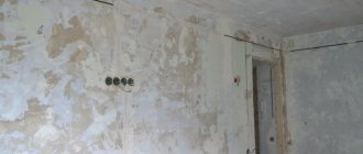
Panel houses make up a significant share of the housing stock of our country. Due to their ease of construction and construction productivity, they have become a popular solution for increasing the amount of living space. But the opposite effect also appeared: the extremely low quality of construction gave rise to many troubles that still haunt the residents of panel houses. One of these aspects was wiring.
Most apartments in “panel houses” have long since undergone their first or even second replacement of the wiring in a panel house: most owners replace outdated aluminum conductors with new copper conductors - this gives much higher conductivity and reduces the risk of a short circuit. Increased requirements for network power leave no choice for residents of such houses - sooner or later, “knocking out” plugs will lead to the idea that the wiring still needs to be improved.
At the same time, the arrangement of conductors cannot be called universal. Many electricians and people who decide to do the repairs themselves often come across insulated wires in the most unexpected places, and replacing electrical wiring in a panel house turns into a real torment. Standard documentation on the location of electrical network elements changed frequently. It is also worth considering that not all foremen put careful execution of the plan at the forefront - the end result was that the wiring diagram was almost chaotic.
Without exception, all residents who have decided to seriously modernize their home have a reasonable question: what to do in this case. There are several ways to avoid damaging the wiring in the socket during repairs or to find the right cable the first time if necessary.
Typical wiring diagram
The typical apartment wiring diagram directly depended on the characteristics of the building and its design features. Below, for example, is electrical wiring in a panel house for the 21st series of panel houses - the first generation of panel houses without a frame.
You should immediately pay attention to several details:
- A separate group of wires was installed in each room, which made it possible not to disconnect all rooms from power during repairs (for example, if the wiring in an apartment is being replaced).
- A separate distribution box was used for corridor sockets, bell and lighting in front of the apartment.
- A separate branch of the network is the kitchen and lamps. They had an increased cable cross-section, since many houses of the 21st series did not provide for the installation of gas stoves and the initial groundwork was made for the use of electric ones.
- A separate line was allocated for the bathroom and toilet. The junction box was missing.
Generally speaking, the scheme is very simple and understandable - even an amateur can figure it out. But another question is to what extent the builders and electricians themselves followed these recommendations. There were several reasons for this:
- Rejection of slabs . Often, the grooves provided for laying wiring in an apartment panel building did not have the proper dimensions - they were clogged with crushed stone or concrete. Therefore, wiring was often done under the floor or in unsuitable places.
- Downtime in construction . Houses that were preserved for a period of two years or more experienced very strong shrinkage - due to the relatively high height and lack of a frame. Therefore, the joints between the slabs were often uneven. Sometimes it was these gaps that electricians used to lay wires, and before replacing the wiring, they should be checked first.
- Desire to save time . There is also a rather prosaic and weighty reason that caused the chaotic arrangement of wiring in an apartment panel building.
What's the result? Above you were given a diagram of a typical cable layout that should be in this apartment. Below is a real diagram that was created by one of the owners in the apartment of a panel house during the renovation process:
The differences are visible to the naked eye:
- distribution boxes are in the wrong places;
- conductors are almost nowhere located parallel to the floor and ceiling;
- instead of four lines, only two were made;
- The power supply scheme has been completely changed.
Consequently, only one conclusion suggests itself: before changing the wiring, you can find out in the house’s passport its year of construction and series, then finding on the Internet a standard diagram taking into account SNiP and GOST. But in almost all cases it will be very different from the original for the reasons stated above. Therefore, it is better to detect conductors in a panel house yourself. It is also important to replace the wiring in a panel house in accordance with all standards so that its operation, maintenance and repair cause a minimum of hassle (as in the figure below). It is worth remembering: in many series, gating walls for wiring is prohibited - in a number of “panels” all walls are load-bearing at the same time and this can lead to very disastrous consequences.
Wiring diagram in a panel house
The panel method of housing construction has always presented the inhabitants of Soviet-built apartments with a lot of surprises and surprises. Very often, during the process of renovating an apartment in a panel house, an attempt to hang a picture or knock out a couple of holes in the wall with a hammer drill in order to install kitchen cabinets led to a short circuit. The drill or punch came across old aluminum wires in the most unexpected places on the walls.
Search using the device
One of the best methods for finding out where the wiring is in prefabricated houses is a device for finding hidden cables . There are several variations of the device that work on different principles. The most primitive ones measure the voltage of the magnetic field: current passing through a wire creates lines of force around it, which are recorded by the device. This method has a drawback and it is quite significant: the wire may be de-energized and safely “forgotten” in the wall by the master during a previous redevelopment. Also, such solutions have rather low noise immunity, although modern solutions do not have this drawback. Homemade devices also deserve special attention, but in most cases the apartment owner will not have the time, parts, or necessary skills to create it.
Another option is a small metal detector . It works in reverse. If the first type of device recorded the magnetic field emitted by the wire, then the second one generated it. In practice, this may not provide any particular advantages when searching for cables, although only such a device can find de-energized sections of the network. Another thing is that, in addition to conductors, he is also looking for fittings: when working with a hammer drill, this will be a huge plus. So in the long term, it is recommended to purchase just such a hidden wiring sensor.
The most common solutions of this type are:
- "Woodpecker" . A domestic device that emits a magnetic field and registers its increase in the surrounding space. It has an acceptable search depth - from 7 to 10 centimeters in the wall of a panel house. Allows you to search not only for a line, but also for where it breaks. A cheap and very effective device, the capabilities of which are sufficient for almost every amateur or professional. Negative reviews about the “Woodpecker” are also widespread: if the wire is buried at a large depth, the device may not recognize the conductor or give false signals.
- Sensors type MS . Chinese solutions based on the same principle. Unlike the Woodpecker, they have an antenna that amplifies the signal. This does not greatly affect the depth of the search or the quality of work - there are also rarely any complaints about the device. Sometimes the sensitivity of the device is even too high, which can “come out sideways”: sometimes MS even reacts to a nail left in the wall a long time ago. In theory, this is a big plus for working with a hammer drill, but for many it is more of an inconvenience than an advantage.
- Bosch DMF . An advanced device from a higher price category. It has a screen that shows the thickness and depth of the conductor. There is also a sound indication. The device works flawlessly, but is much more expensive. Excellent for detecting wiring in a panel house even under a thick layer of plaster: the stated sensitivity is 10 centimeters, but in practice it is much higher than this figure.
It is also worth mentioning separately about the third type of devices, which are often positioned as solutions for finding hidden wiring in a panel house - thermal imagers . The operating principle of the devices is as follows: they have a screen and a camera that films in the IR (infrared) spectrum. This allows you to locate heating wires and determine how overloaded the line is.
This method has exactly one disadvantage, but it is very significant: with a thick layer of plaster, the heat will dissipate very quickly and the device will simply be useless. Do not forget that its cost is almost an order of magnitude higher than universal devices from Bosch. Thermal imagers are more suitable for shallow wiring or for monitoring cables that are not located inside walls. But in this case, you can use the usual “father’s” method: simply move an indicator screwdriver from a regular outlet along the wall and draw a line along which the wire runs.
Household repair No. 1
Choose reliable craftsmen without intermediaries and save up to 40%!
- Fill out the application
- Receive offers with prices from masters
- Select performers by price and reviews
Post a task and find out prices
One of the stages of repair is laying an electrical network. This type of communication requires replacement over time. It is necessary to take into account a lot of nuances - design and draw up an electrical wiring diagram, choose methods of connecting circuits, type of wiring, comply with all fire safety conditions, etc. It is also necessary to remember that the electrical wiring diagram for different apartments, depending on the number and location of their rooms, will also have its own characteristics.
If there is no money for the device and no circuit
In some cases, searching for wiring is a fundamental task: for example, you urgently need to make a through hole in the wall, hammer in a dowel or nail. In such cases, you can use the means at hand to understand where the wiring is located in the panel house:
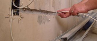
- Indicator screwdriver . This method was already briefly mentioned in the previous section of our article. A conventional indicator screwdriver detects voltage, and therefore it also detects wires with thin insulation at a shallow depth without problems. You can start your search from an outlet or chandelier and move the tool along the wall to the point near which you plan to work. The accuracy of the method is very high (plus a couple of centimeters of minutes), but it cannot be called universal.
- When making major or cosmetic repairs, you can simply take a closer look at the walls and look for differences in the color of the plaster . Lighter, rough stripes of a different texture are probably grooves for wires. For them, a slightly less liquid solution is most often used, and they are made much later - the difference will definitely be noticeable to the eye.
- Radio receiver . Surprisingly, even with the help of an ordinary radio receiver you can make your own improvised wiring diagram in an apartment panel building. To do this, you need to turn on the device and tune it to a frequency of 100 kilohertz (kHz). It is in this range that cables begin to emit interference - this is where the law of unity of electric and magnetic fields works. You need to move the antenna along the wall as if it were a specialized device or an indicator screwdriver. The only drawback is that the method has low accuracy. The error can be up to ten centimeters, and therefore when working with a drill or hammer drill, it is better to retreat the same amount in order to avoid troubles.
- Microphone . In fact, the microphone is also an antenna - these devices use approximately the same operating principle, although they have different sensitivity ranges. However, in the complete absence of a tool, it will help you find a groove in a panel house and avoid unpleasant situations. You need to turn on the microphone in the recording device and turn up the speakers. Then you need to run it along the wall at a distance of 1–2 centimeters. A characteristic sign of detected wiring is a characteristic crackling sound. The accuracy of the method is no higher than that of a radio receiver. It is also supposed to make a reserve to prevent electric shock.
Stages of cabling throughout the premises of a two-room apartment
Cable distribution throughout the premises of a two-room apartment should be carried out in the following stages:
- drawing up a wiring diagram;
- calculation of the number of required materials, electrical fittings;
- marking, as well as gating of walls;
- fastening cable wires;
- installation of switches, sockets, and distribution devices;
- assembly of the input panel;
- testing the assembled line using a multimeter.
Let's take a closer look at drawing up the diagram. The wiring diagram for the electrical wiring in the apartment can be drawn up with your own hands, taking into account some recommendations.
An example of wiring layout in a two-room apartment
Tips for drawing up an outline
To draw up a wiring diagram with your own hands, you can use a copy of the apartment plan, where it is very convenient to mark the connection points of lamps, switches and sockets.
various designation elements on the diagram
The starting point of the diagram is usually taken to be the location of the distribution panel, which is often located in the corridor near the front door. When drawing up a diagram with your own hands, we recommend using the following tips:
- It is customary to run electrical wiring lines in an apartment strictly vertically or horizontally, which helps reduce the risk of damage when drilling walls for various purposes.
do wiring horizontally or vertically
- It is better to lay the electrical wiring line 20 cm from the ceiling or along the floor using a special electrical plinth.
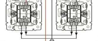
- It is recommended to conditionally divide the lighting line and power line into several groups with a separate circuit breaker connected to each group. For example, one circuit breaker will be responsible for lighting the bathroom and hallway, and another will be responsible for the light in the kitchen, bedroom and living room. The layout of the line of sockets in a two-room apartment should also be divided into groups.
example wiring diagram and single line diagram with different connection groups Each room (except the bathroom) should be equipped with its own distribution box. It is recommended to install electrical wiring in the bathroom from a junction box located in the hallway.in the diagram you can see the blue circles marking the distribution boxes for each room. If the owner of the apartment wants to make the balcony lighting with his own hands (since the developer does not expect this), you can take out a separate cable from the distribution box located in the next room.
example of wiring arrangement in a two-room apartment and power supply to the balcony
- In the case of a large winding room, lighting is best done using several lamps, which will be controlled from a two-key switch. If this condition is not met, then the lighting in the apartment may be insufficient.
- During installation, it is usually recommended to place sockets 30 cm from the floor level, but they can also be located at a higher height (for example, above the working surface of a table).
It is recommended to install at least one socket for every 6 m2 of room. And in the kitchen it is better to make as many sockets as there are household appliances (usually 5-6 pieces). location of sockets in the room - Before drawing up a wiring diagram with your own hands, carefully plan the future arrangement of furniture and appliances in the rooms in order to subsequently avoid the furniture blocking sockets or not reaching cords from household appliances to power sources.
- It is imperative to include an RCD (residual current device) rated at 30 mA in the wiring diagram. For a bathroom, it is better to install an additional RCD with a current of 10 mA. It can protect cables from overheating in the event of a short circuit, current leakage or network overvoltage.
conclusions
In order to find (or install) a wiring diagram in an apartment panel building, you need to know data about the house itself. The luckiest ones will be able to find documentation for this particular type of construction, but they will have to rely on the builders to comply with it unquestioningly. Do not forget that the channels intended for routing wires often had manufacturing defects - they were clogged with rubble or did not have sufficient depth at all.
It is also worth remembering the basic principles of cable management that were followed in all Soviet houses:
- conductors run only perpendicular or parallel to the walls;
- the distance of the wire from the ceiling and floor is at least 15 centimeters;
- turns of the wire look like right angles.
But one should not rule out the appearance of cables under the baseboards or floors - such passages were not uncommon in panel houses. Particular attention should be paid to the gaps between the slabs: the ban on placing wires in them was often ignored by electricians for lack of other options.
Of greatest interest to craftsmen are devices for finding hidden wiring. It is much better to choose portable metal detectors - they will help you find both de-energized conductors and live wires. Budget solutions include the domestic "Woodpecker" and the Chinese MS, and in the more expensive segment - Bosch. It is better not to use thermal imagers and improvised means (indicator screwdriver, receiver, etc.): the search depth is a couple of centimeters, and the accuracy leaves much to be desired.
Source: ProFazu.ru
How to install electrical wiring in a panel house according to the diagram
Within 2-4 years from the completion of construction, shrinkage processes occurred in the panel house with mutual movement of the slabs and settlement of the foundation. In such cases, electrical wiring running into the panel seam could be severed or crushed. At the same time, it was almost impossible to find the place of a fault or break in an aluminum core in the house. It was necessary to resort to the services of an electrician to sort out the tangle of electrical wiring and carry out its repair or complete replacement.
There was a standard layout of electrical wiring in an apartment, as in the diagram above, but adaptation to various projects of apartments in panel houses was carried out extremely carelessly. The main thing was to maintain a uniform load across the phases in such a way as to avoid overload and, as a result, not get phase imbalance.
Choosing a method for laying electrical wiring in an apartment
Open wiring
So:
- Before developing a wiring plan for a two-room apartment, we should decide on its basic parameters. One of these is the method of laying it. At the moment, two options are used - open and hidden.
- Open wiring has certain advantages:
- To install it, there is no need to trench the walls. That is, you can completely replace all wires without subsequent repairs throughout the entire apartment.
- Open wiring is installed very quickly. And with the proper skill and availability of workers, it can be completely installed in literally a day.
- If you need to connect new electrical receivers or carry out repairs, you do not need to break down the walls.
- Installation of hidden wiring is carried out in special boxes. In this case, the wire in the boxes usually has additional protection in the form of a metal or self-extinguishing corrugated pipe. You can, of course, install it without using special boxes, but this option is more suitable for utility rooms and sheds, but not for apartments.
- Branches to sockets and switches are also made using a special box. And the sockets and switches themselves must be designed for an open circuit.
- An electrical wiring diagram can also be used in a two-room apartment with its installation in baseboards. But this method has significant limitations on the number of wires used and is often used only for wiring in individual rooms or for laying to individual electrical receivers.
Hidden wiring
So:
- More common is the wiring diagram in a two-room apartment using hidden electrical wiring. This method has the following advantages:
- Due to the fact that all elements of such wiring are hidden from prying eyes, it has a more attractive appearance
- Doesn’t take up free space in our already small apartments
- Hidden wiring has higher throughput and overload capacity due to better heat transfer.
- Due to the lower requirements for protection from mechanical damage, the price of the necessary materials is noticeably lower.
- Installation of hidden wiring is carried out directly in the structural elements of your apartment. To do this, small recesses are made in the wall - grooves. Wiring is laid in them, followed by plastering.
- To install sockets, switches and distribution boxes, recesses are also made in the wall. They are then installed with sockets and switches designed specifically for the hidden circuit.
What tools will you need?
Independent replacement of electrical wiring is carried out using the following tools:
- perforator;
- concrete drill, concrete drill (16-20 mm), core drill (90-100 mm);
- chisel 25-30 mm;
- soldering iron 40 W;
- grinder with a disc for stone;
- screwdrivers;
- pliers;
- side cutters;
- phase indicator;
- tester;
- cord and level;
- flashlight;
- stationery knife;
- putty knife.
Calculation and selection of power supply scheme
Posting calculation
So:
- Before we begin directly calculating our electrical wiring, we need to decide on the number of electrical receivers. To do this, it is necessary to accurately determine the number and location of each outlet and lamp. Without this clear plan, further calculations are impossible.
Note! You should not deliberately overestimate the number of outlets or lighting you require. You only need those outlets to which you know exactly what will be connected. Installing sockets and lighting circuits just in case, significantly increases the cost of your electrical system and increases your labor costs.
- Now having a clear idea of the number of electrical receivers, we can proceed directly to the calculations of the required wire. But the capacity of the wires in clause 1.3 of the PUE (Electrical Installation Rules) is indicated in amperes, and the power of all our devices is usually indicated in watts.
- Using Ohm's law, which everyone should know from school, we recalculate: where P is the power of the device in Watts (W), U is the voltage of your electrical network in volts (V), for a single-phase network the voltage is 220V, and I is This is the current that will flow in the wires in amperes (A).
- Having made a simple calculation, we find that when connecting a 1000W device, a current of 4.55A will flow in our wire. Our instructions advise rounding this value to 5A to create a certain margin and simplify calculations.
- Now let's start choosing the wire. It can be made of copper or aluminum and is insulated with polyvinyl chloride or rubber. The choice should be made in accordance with clause 1.3 of the PUE. It includes a conductor depending on laying conditions, insulation, humidity and some other parameters.
- But all this is quite complicated and with small loads in the apartment it is not always justified. Therefore, if you are not a design office and are replacing the wiring yourself, then we advise you to use a simplified calculation. According to it, a copper wire with a cross-section of 1 mm2 in normal mode passes a current of 10A, and an aluminum wire with the same cross-section - 5A.
Selecting a wiring diagram
So:
- Having calculated all possible loads, we should divide them into groups. In this case, we will be guided by clause 6.2.2 of the PUE, which states that group lines must be protected by circuit breakers for a current of no more than 25A. At the same time, if you create a separate group for the lighting network, it is usually equipped with a 16A circuit breaker.
- When dividing the load into groups, the power of consumers should be taken into account separately. These include electrical equipment with a power of 2 kW or more. These are usually heating and heating devices. If you have any, then they should be powered by a separate circuit breaker with the appropriate rated current.
- Without taking into account powerful consumers, your wiring plan for a two-room apartment should have two to three groups. One of which is the lighting network and one or two groups are power sockets. If you end up with two groups feeding outlets, then it is advisable to form groups in adjacent rooms. That is, one group powers the sockets in the kitchen and hallway, and the second - in the bedroom and living room.
Note! According to clause 7.1.37 of the PUE, installation of sockets in the bathroom is permitted only when connected through an RCD. If you are installing an outlet in the bathroom, it is advisable to include it in the group that powers the kitchen outlets. After all, although sockets in the kitchen do not require the mandatory installation of an RCD, this protection device in the kitchen will be most appropriate.
- Separately, I would like to dwell on the cross-section of the wires used. For groups with a 25A circuit breaker, the copper wire must have a cross-section of at least 2.5 mm2. Accordingly, for 16A groups, at least 1.5 mm2. But in any case, the cross-section of the wire feeding a separate group is not advisable to make more wires on the input machine.
Note! According to table 7.1.1 PUE, the minimum cross-section of the copper wire to the input circuit breaker must be at least 2.5 mm2. At the same time, the minimum cross-section of the group wire should not be lower than 1 mm2.
Features of installation in Khrushchev
The diagram of the selected wiring for installation in a Khrushchev-era standard two-room apartment is based on consumer groups. These include lighting devices, household and power sockets, a bathroom and a corridor. The arrangement is carried out using two technologies.
Hidden way
In brick or panel houses, wires can be laid in three ways:
- Inside the ceiling, the route from the switchboard goes vertically, runs along grooves or in a corrugation. Internal ceiling tiles already have channels from where you can run power cables to lamps, switches, and sockets. The wiring runs perpendicularly, without falling horizontally below 15 cm. Each distribution box has an individual automatic switch.
- Under plaster - wires are inserted into pre-drilled holes, fixed, and brought out to consumers. The lines are masked with a layer of plaster, which prevents them from being damaged by voltage fluctuations.
- Under the floor - the line is routed under the floor surface. Channel pipes are laid, which are then filled with solution. Lines for sockets and lighting are masked with a mounting box or pipe.
With a combined connection, pipes and cables are distributed at an acute angle. The routes are connected via a distribution box to the input panel.
Open way
The open option is used when it is impossible to organize the electrical network in another way. There are several methods:
- On the brackets - for sockets you need copper wires with a cross-section of 2.5 mm2, for lighting - 1.5 mm2. Metal strips are used as staples, fixing them so that the non-flammable part extends 1 cm beyond the line.
- In pipes, corrugated flexible products prevent surface leveling. The diameter of the pipe is equal to the total thickness of the conductors, multiplied by 2. Fastening is done with screws, clips, dowels and nails. Each element is removed from each other by 20-40 cm.
- The boxes contain a metal or plastic cable channel and the baseboard is equipped with a removable lid with a latch. The main difficulty of the work is the correct fastening with screws, dowels or staples. Sockets can be mounted directly onto the box.
If the apartment has a retro interior, the wires do not need to be masked.
Electrical wiring installation
So:
- Of course, at the moment there are numerous videos of correct wiring, but we will only focus on certain points. It is advisable to make grooves in the upper part of the wall, right under the ceiling. Of course, some people make it easier for themselves and place the electrical wiring in the screed. If you are pouring a new screed, then this option is certainly quite convenient. But if the wiring is damaged, you will have to knock out the tie, which in certain cases may lead to the need to completely replace it. In addition, the risk of electric shock increases when the room is flooded.
- Your electrical wiring diagram in a 2-room apartment must necessarily contain junction boxes. It is advisable to place them at the entrance to the room on the wall closest to the door handle. This is due to the fact that this is where the room light switch will be located and from here it is much more convenient to carry out subsequent wiring.
- When laying several wires of different groups in one groove at once, it is advisable to separate them with fireproof material. This could be a layer of plaster or a corrugated metal pipe. This will prevent damage to several wires at once if one of them catches fire or overheats.
- When connecting sockets, switches and other electrical receivers, you should leave a small supply of wire, sufficient for re-cutting the wire and reconnecting.
Instructions for replacing wiring
At the preparatory stage, it is necessary to conduct a visual inspection and check the quality of the connection. Further operations are performed according to an algorithm developed by professional electricians.
Blackout
To gain access to the system and avoid electric shock, you will need:
- Turn off the main circuit breaker from which the cables go to the apartment.
- Check for voltage.
- De-energize each wire, first checking it with a phase indicator.
- Test switches and sockets for voltage.
The old wiring can be left in place without damage.
Dismantling old wires
The electrical wiring is dismantled after the electricity is completely turned off. This can be clarified using a multimeter.
First, local dismantling is carried out from the distribution box under the ceiling. It is opened, the input cable is found and removed. If the wire does not stretch, it is cut further and then insulated. Further work is carried out in a similar way.
Surface preparation
The wall can be chipped horizontally or vertically.
- Marking the locations of socket boxes according to the drawings.
- Marking places for sockets with the ability to disguise the cord.
- Accurate determination of channel boundaries with a puncher.
- Manual alignment of holes with a chisel.
- Making an oblique cut with a grinder for an even position of the wire.
- Making holes in a brick wall using a crown attached to a hammer drill.
Crooked grooves often cause cable breaks and fires.
Line grounding
Installation of a protective line in houses built in the period 1960-1980. was not provided. To solve the question of where to get grounding in a Khrushchev building, you will need to make a grounding:
- Connect the ground contact in the socket to zero.
- Bring the structure onto the shield from the outside.
A connection in which the input circuit breaker turns on “zero” while the current protection is operating is prohibited by regulations.
Installation
Installation of the new power line is carried out in stages:
- Installation of socket boxes on alabaster in holes.
- Cutting cables and corrugated pipes to the required length.
- Pulling the wire inside the corrugation on a flat surface.
- Laying the corrugation in the groove with the cable ends inserted into the socket box.
- Aligning the hole along the wall line.
- Putty the grooves in small sections, every 50 cm.
- Planting the second end of the corrugation onto the input panel.
- Treating the ends of the wires with paste, fastening them with a clamp and fixing them to the protection terminal of the shield.
Lead the apartment wiring into the panel suspended.
Checking and plastering
Testing of the finished system is carried out as follows:
- The electricity is turned off and current is supplied.
- Each cable branch is checked by a tester for short circuits. For this purpose, the indicator is zero and phase.
- Output the wires to the appropriate terminals.
- Retest for short circuit.
- Turning on the main circuit breaker, supplying electricity.
Be sure to look at how lamps, switches, and sockets work.
At the last stage, a primer is applied to the wall surface, then a layer of plaster and finishing.
Independent replacement of the electrical line in Khrushchev-era buildings is complicated by old wires, an incomprehensible connection diagram, and lack of grounding. For this reason, it is worth adhering to the exact sequence of work, drawing up detailed drawings and consulting with specialists.
A huge number of Russians, Belarusians and residents of other countries still live in Khrushchev buildings. Structural elements, be it foundations, floor slabs, flights of stairs, can last for decades. But communication systems have a significantly shorter resource, and, accordingly, need repair or complete replacement. Electrical wiring requires special attention in Khrushchev. Its replacement guarantees safe and full use of all modern household appliances.
Conclusion
The wiring diagram of a two-room apartment, first of all, should be simple and intuitive. There is no need to complicate it by scattering electrical receivers of one group throughout the apartment. After all, you now remember all the nuances of the wiring, but in a year or two it may be forgotten. Therefore, when laying wires, use only right angles, and when distributing sockets of one group, there is no need to distribute them in different rooms.
Source: Elektrik-a.su
Living spaces for people are constantly being improved. There are more and more electrical appliances that improve life. Electricity consumption increases, and the wires laid during construction are exhausted: the metal and insulation age, losing properties from overloads, heating, ultraviolet radiation and mechanical influences.
Aluminum wiring, in use since Soviet times, has long been in need of replacement. Increased safety requirements abolished the TN-C system, which did not provide for grounding of electrical appliance housings, the use of a potential equalization system, or protection against leakage currents.
Owners of old apartments do not always imagine how wires are placed in their premises, because there are many options for laying them.
Types of schemes
The main classification of electrical wiring is carried out according to the type of installation:
- open;
- closed.
The first method allows you to visually observe the passage of the routes. It is more affordable and is most often used in wooden houses.
It is more difficult to detect wires hidden in walls, floors or ceilings: they are not visible. They were laid differently in each building, but principles can be identified that take into account the construction period, wall materials, and installation technologies.
Aluminum electrical wiring of a one-room apartment
This scheme is common, has been used for a long time, is well suited for a larger number of premises, and is easy to understand and implement.
In old houses, on each floor there is an electrical panel with a meter, a packet switch to relieve voltage when working with metering devices and circuit breakers. All equipment is sectioned for each apartment separately.
Rice. 1. Option of old electrical wiring of a one-room apartment
For clarity, the picture shows two distribution boxes in each room, but, most likely, the circuits of sockets and lighting are switched through one.
There is no grounding loop provided here. The circuit uses exclusively zero and phase, and the neutral wire should never be broken anywhere by switching devices. It is supplied directly to all consumers through distribution boxes, and is taken from the meter.
To connect the wires, most likely, simple twists with or without welding are used, although screw terminal blocks may be found. The most wires go to the place where the zero is assembled.
The phase from the meter goes to the circuit breakers. In our example, one powers all the outlets, and the other powers the room lights. If the apartment is equipped with an electric stove, then the voltage is supplied to it through a separate circuit breaker, and the wires are used with increased power: up to 10 mm2.
Variations of the scheme are possible:
- fuses are used instead of automatic machines;
- When installing wires after the meter, electricians confused the phase directions with zero (the circuit does not lose its functionality, but is more dangerous);
- a group of machines has been added and consumers are powered according to a different scheme, for example, for a corridor.
Each specific circuit should be carefully understood; it is quite possible that there will be jumpers, additional wires, even installation without junction boxes.
A simple method helps to understand the principle of circuit design:
- turn on all lighting devices and plug in electrical appliances;
- turn off consumers one by one using automatic switches in the distribution panel and observe the extinguished lamps and switched off devices in the sockets;
- analyze changes, write down or remember information, draw conclusions.
Where to start replacing electrical wiring
At the preparatory stage, a plan diagram of new wiring in a two-room apartment is drawn up. It is agreed upon by BTI and Energosbyt. Preparation also includes:
- Visually inspect the line for visible damage.
- Drawing up a drawing of the electrical systems of the entire house.
- Purchase of consumables - sockets, cables, switches, boxes.
- Search for the necessary tools - a hammer drill, an angle grinder, an indicator, side cutters, a level, a flashlight, a mounting knife, pliers, a soldering iron, fabric insulating tape.
Buy wire with allowances after measuring the length of the route.
Power calculation
It is necessary to replace the electrician so that further failures and network overvoltages do not occur. The line power is selected taking into account all electrical equipment and depends on the cable cross-section. You will need to make several calculations:
- Sum up the power of all equipment connected to the power grid.
- Add +100 W to each device.
- Divide the total by 220.
If the result is 12-15, it is permissible to use a cable with a cross-section of 1.5 mm2. This is enough for an apartment with a standard layout.
When there is a heavy load on the line, it is allowed to increase the cable cross-section and arrange communications using a two-wire or three-wire circuit.
When using thick wire there are risks of failure.
Apartment power supply diagram
In old houses, on each floor there is an electrical panel where there is a meter, a batch switch, and circuit breakers. Therefore, when designing a wiring diagram in a two-room apartment, it is worth making an independent power and lighting circuit, planning the main and additional branches. The following connection options are allowed in Khrushchev buildings:
- Parallel - energy is supplied to the consumer from the power source via its own line. A three-core cable is connected to a single-phase device, and a five-core cable with wires of phases A, B, C, zero and ground is connected to a three-phase device. Such a scheme provides for the organization of each consumer’s own line and the installation of an individual RCD.
- Serial - a cable is pulled from one power source, and the consumer is connected to it at a certain distance. To implement the scheme, you will need a wire with a large cross-section and grooves in the walls. The energy source will be a generator producing a nominal 220 V. To save money, you can stretch the electrical cable from the panel to a specific consumer.
- Series-parallel - the circuit is used in most apartments. The distribution box is designed for consumers grouped by type (boiler, sockets, light) or location (kitchen, bedroom, bathroom).
A series-parallel connection is the best option for a budget-friendly complete replacement of the electrical network.
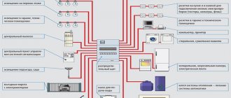
The main electrical diagram of the apartment: its components
The electrical diagram of the entire apartment is usually drawn up not on one sheet, but on several separate ones. Each of them will indicate only one distribution group, so the diagram will be easy to understand and read. To do this, at the beginning, consumption sources are divided into several groups, the location of which is indicated on the diagram.
Each such group should be connected to one separate machine. This will be very convenient when repairing wiring, since it will be possible to disconnect the wiring of only one of the rooms, and not the entire apartment.
The electrical diagram of the apartment can be drawn up on a computer using a special program
A typical electrical wiring diagram in an apartment contains several components, each of them performs its own specific tasks.
Basic wiring diagrams:
- Structural . This diagram should be created very first, since it indicates the panel and its connection with electrical appliances that will be installed in the apartment.
- Functional . It depicts electrical wiring elements and the connection between them with special symbols.
- Principled . This is a more complete and detailed diagram, on which all lamps, switches, sockets, as well as household appliances are already indicated. They indicate the lines where the wire runs, as well as the locations of junction boxes and other elements, and various connections.
- Calculated . This circuit is the most important; it is created specifically for electrical panels. The electrical panel contains input circuit breakers and protection switches, with which you can turn off any consumer group.
- Assembly room . This diagram is done very rarely, since an experienced electrician will only need a design diagram.
Next, a plan of the entire apartment is drawn up, where all lighting and household appliances, sockets and switches are indicated. Each such group has its own wiring, that is, a cable that comes from the electrical distribution panel. All electrical wiring cannot be connected to this group; the bathroom generally needs to be connected to a separate line. And it also needs to be equipped with a difautomatic device or an RCD, for protection and precaution.
Problems with old houses
The construction of Khrushchev-era apartment buildings took place between 1958 and 1985. within the framework of urbanization. The power lines in them differ depending on the series of buildings:
- Buildings from the 1963 period - places for the distribution box, gating, and connecting wires were left to the discretion of the electrician;
- Panel houses of 1965 - wire routing and hidden installation were carried out in the channels of panel slabs;
- High-rise buildings built in 1974 are classified as standard construction according to the requirements of the Unified Catalog of Construction Parts. Due to the poor quality of the channels in the slabs, the wiring was laid in niches under the floor of the upper floors, leading the cables through a through ceiling groove.
In the 60s - 70s. We did not anticipate such a number of electrical appliances, so the network could withstand a maximum load of 3.5 kW. The total power of a modern kettle and iron is 4 kW.
- broke over time with minor bending;
- required complete replacement once every 20 years;
- under voltage was subjected to electrocorrosion, which became the cause of fires.
In 1960-1980 It was customary to ground the power line according to a scheme with a solidly grounded neutral. At the end of the twentieth century, the TN-CS scheme was adopted in the Russian Federation, to which the Khrushchev buildings do not correspond.
Wire twists and uninsulated areas due to the branching method require a complete replacement of the aluminum cable with copper.
Electrics in a two-room apartment: diagram and its symbols
In a panel house, which can also be called frameless, all internal partitions are load-bearing. Therefore, separate openings for wires cannot be made. You need to use the channels provided by the slab manufacturer.
Wiring in a panel house can be laid in some other ways. For example: the most affordable option is to lay the cable along the surface of the ceiling and walls. You can do the same on the floor, only then put a concrete screed on top.
The wiring diagram of the room and the entire apartment looks very modern today. Its main symbols are divided into: sockets, lamps, junction boxes and switches.
Main groups in a two-room apartment:
- Lighting in living rooms 1 and 2, kitchen and hallway;
- Power supply for kitchen and hallway;
- Lamps and sockets for rooms 1 and 2;
- Bath and toilet, sockets and lighting fixtures;
- Electric stove.
Before carrying out electrical work in the apartment, all wires must be checked for damage.
The input cable has three main wires: ground, phase and neutral. All modern wiring is laid in a closed manner, using special corrugated pipes.
DjMaN93 › Blog › Correct electrics for a three-room apartment
As always, hello.
I had a free hour, as a result of which this material was born. I really wanted to title the post “What to do to avoid thinking about defending your dissertation?”, but this title will not be relevant. So, today I want to talk about household goods. The habitation of my apartment is progressing extremely slowly but surely. We have neither time nor money, so for now we are infringing ourselves with bare, unplastered walls and free linoleum. Not scary. Everything is temporary.
There is an opinion that there is nothing more permanent than temporary. I partially agree, but the predominant factor, in my personal opinion, is that people simply do not want to change anything. The reasons are different for everyone, but the result is the same. The desire for something is a set of goals and desires, reduced to an orderly plan of action. The inhibitory factors are usually time and money. However, they can also be included in the plan.
One of the few important principles that I learned at university is that any action must be thoroughly thought out and calculated, otherwise it is a marriage. And even at the stage of developing a plan or project, some things are often not thought through. What would it be like without a plan?
With these thoughts, I began to study a new topic for me: rough electrical engineering and wiring distribution. The existing wiring from the developer was no good - two 3x1.5 mm2 input cables (TU) came from the floor panel to the apartment on the right and left sides of the apartment, sockets and lighting came from the same boxes. I simply could not live with the thought that somewhere in my walls there was such a mess going on... Then I also remembered the recording of one of my modern idols, Andrei Golubev. I got excited about the idea, estimated the budget, became depressed, but decided that, after all, “to be”... I began studying the issue from the basics - the rules for constructing electrical installations. We are mainly interested in Chapter 7.1 - Electrical installations of residential, public, administrative and domestic buildings. I love it when everything is discussed down to the smallest detail. Then I mainly looked at ready-made implementations and master classes on YouTube. From Alexey Zemskov I learned about the existence of walk-through and changeover switches, I had never seen them before.
Convenient and correct electrics are a complete absence of extension cords, visible tails of wires, sockets in all the necessary places in the right quantity, and they are not an eyesore. In addition, each room must have its own groups of lighting and sockets in the distribution board and be protected against electric shock. Now, in order, how to achieve this.
From the very beginning, we need an accurate floor plan with future furniture and household appliances; this will allow us to accurately determine the installation locations of all sockets and switches. I drew on paper in a top view, specifying every little detail and taking into account all the dimensions. As a result, I counted about 60 sockets, 12 simple switches, 8 pass-through, one changeover, four TV sockets, four HDMI sockets, four LAN sockets. The layout of each room looked something like this:
At this same stage, it became clear that a refrigerator would not fit into a square kitchen. I decided to drop the wall and line it up with a niche for the refrigerator. This pushed back the electrical plans for another couple of months, but I was able to see the scale of the problem early and solve it radically.
Source: www.drive2.ru
Electrical wiring in Khrushchev: diagram and installation of hidden wiring
Hidden wiring is electrical wiring that is directly located in the elements of all building structures. Such wiring includes cables laid under screeds, in different cavities of building elements and, most commonly, under suspended ceilings.
When installing electrical wiring, the most important thing is to make the correct calculations and choose a suitable electrical network diagram. If these two elements are correctly selected, then it will be easier for you to install all the electrical wiring.
You can directly install electrical wiring in a Khrushchev-era building yourself, knowing all the necessary parameters, as well as the number of groups and the size of the room. If something is unclear, you can always take the advice of a competent electrician.
Wires in Khrushchev must be well insulated according to safety regulations
Advantages of hidden wiring:
- Attractive appearance;
- Does not require additional distribution boxes;
- Can withstand high loads;
- Strict fire safety requirements.
Correct calculation, as well as competent installation, guarantee you uninterrupted power supply and at the same time eliminate the likelihood of a short circuit or fire.
How to lay new lines
If you just need to replace the electrical wiring in a Khrushchev-era building, it is simply laid through the same channels in the slabs. To do this, screw a new one to the cores of the old cable and pull it through. If the cable does not stretch - perhaps there is a walled-up junction box or socket somewhere and the cable is held on asbestos or plaster - you need to find where it is. When you break it, the line will pull through with ease.
The video below clearly shows how to do it correctly:
But if you want to increase the number of outlets or move them, difficulties arise. It is not always possible to groove load-bearing slabs.
Important! You cannot make horizontal grooves. According to some regulatory documents, this is prohibited, for example, Decree of the Moscow Government of February 8, 2005 N 73-PP “On the procedure for renovating premises in residential buildings in the territory of the city of Moscow” and its editions. There is also information about the prohibition of horizontal grooves in slabs longer than 3 meters. This is due to the fact that due to the axial load, the slab can “fold” along the groove. Therefore, it is worth doing without gating.
Let's consider 3 options for laying new wiring lines in Khrushchev. New lines are being laid:
- By gender. The cables are laid in corrugation under the screed in the floor. The disadvantage is that it is difficult if the cable fails - you will have to hammer out the tie. We talked about how to install electrical wiring in the floor in a separate article.
- In the baseboards. There are a number of baseboards on sale with cable channels, in which case you will only need to make a small vertical groove to the new outlet. You can learn more from the article: how to conduct wiring in a baseboard.
- Under a suspended or suspended ceiling, or behind other elements of plasterboard structures. You will also have to make vertical grooves, but this is actually a kind of external wiring laid in a corrugated pipe along the ceiling or its corner with the wall.
Interior partitions made of brick, aerated concrete, shingles and other materials can be grooved and lines laid as you wish.