Electric circuit and inductance
Inductance serves to characterize the magnetic properties of an electrical circuit. It is defined as the proportionality coefficient between the current electric current and the magnetic flux in a closed loop. Flux is created by this current through the surface of the loop. Another definition states that inductance is a parameter of an electrical circuit and determines the self-inductive emf. The term is used to indicate a circuit element and is a characteristic of the self-induction effect, which was discovered by D. Henry and M. Faraday independently of each other. Inductance is related to the shape, size of the circuit and the value of the magnetic permeability of the environment. In the SI unit, this quantity is measured in henry and is denoted as L.
Units
In the SI system of units, inductance is measured in henry, abbreviated as Hn. A circuit carrying current has an inductance of one henry if, when the current changes by one ampere per second, a voltage of one volt appears at the terminals of the circuit.
In variants of the SGS system - the SGSM system and in the Gaussian system, inductance is measured in centimeters (1 Hn = 10⁹ cm; 1 cm = 1 nH); For centimeters, the name abhenry is also used as a unit of inductance. In the SGSE system, the unit of measurement of inductance is either left nameless or sometimes called stathenry (1 stathenry ≈ 8.987552•10⁻¹¹ henry, the conversion factor is numerically equal to 10⁻⁹ the square of the speed of light, expressed in cm/s).
Self-inductance and inductance measurement
Inductance is a quantity that is equal to the ratio of the magnetic flux passing through all turns of the circuit to the current strength:
- L = N x F: I.
The inductance of the circuit depends on the shape, size of the circuit and the magnetic properties of the environment in which it is located. If an electric current flows in a closed circuit, a changing magnetic field arises. This will subsequently lead to the occurrence of EMF. The birth of an induction current in a closed circuit is called “self-induction”. According to Lenz's rule, the value does not allow the current in the circuit to change. If self-induction is detected, then an electrical circuit can be used in which a resistor and a coil with an iron core are connected in parallel. Electric lamps are also connected in series with them. In this case, the resistance of the resistor is equal to the DC resistance of the coil. The result will be bright burning lamps. The phenomenon of self-induction occupies one of the main places in radio engineering and electrical engineering.
Lenz's Law
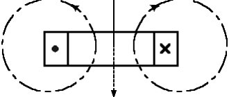
Lenz's law tells us that the induced current is directed so as to oppose the cause that caused it. For example, we apply voltage to the coil. A magnetic field is formed in the coil which, at the moment of switching on, crosses the turns of the coil and induces an electromotive force of self-induction there. According to Lenz's law, the induced EMF of self-induction will be directed towards the current that caused it.
If you apply (a) and remove (b) voltage from the coil, the following will happen. The magnetic field will appear and disappear. As a result, the changing magnetic field will cross the turns of the coil and induce an emf in it.
New concept of self-induced emf. Let's take a closer look at it.
How to find inductance
The formula, which is the simplest for finding the value, is the following:
- L=F:I,
where F is the magnetic flux, I is the current in the circuit.
Self-inductive emf can be expressed through inductance:
- Ei = -L x dI : dt.
The formula suggests a conclusion about the numerical equality of induction with EMF, which occurs in the circuit when the current changes by one ammeter in one second.
Variable inductance makes it possible to find the energy of the magnetic field:
- W = L I2 : 2.
INDUCTANCE – Studiopedia
Electric current creates its own magnetic field. The magnetic flux through the circuit is proportional to the magnetic field induction (Ф ~ B), the induction is proportional to the current strength in the conductor (B ~ I), therefore the magnetic flux is proportional to the current strength (Ф ~ I).
The self-induction emf depends on the rate of change of current in the electrical circuit, on the properties of the conductor (size and shape) and on the relative magnetic permeability of the medium in which the conductor is located.
A physical quantity showing the dependence of the self-induction emf on the size and shape of the conductor and on the environment in which the conductor is located is called the self-induction coefficient or inductance.
Inductance - physical. a value numerically equal to the self-inductive emf that occurs in the circuit when the current changes by 1 Ampere in 1 second.
Inductance can also be calculated using the formula:
where Ф is the magnetic flux through the circuit, I is the current strength in the circuit.
SI units of inductance:
The inductance of the coil depends on: the number of turns, the size and shape of the coil and the relative magnetic permeability of the medium
(core possible).
Mutual inductance is a quantity characterizing the magnetic coupling of two or more electrical circuits (circuits). If there are two conducting circuits, then part of the magnetic induction lines created by the current in the first circuit will penetrate the area limited by the second circuit (i.e., it will be linked to circuit 2).
Magnetic flux Ф12 through circuit 2, created by current I1 in circuit 1, is directly proportional to the current:
The proportionality coefficient M12 depends on the size and shape of circuits 1 and 2, the distance between them, their relative position, as well as the magnetic permeability of the environment and is called mutual inductance or the coefficient of mutual induction of circuits 1 and 2. In the SI system I.V. measured in Henry.
Transformer EMF. The operating principle of the transformer is based on the phenomenon of electromagnetic induction. The induction lines of the magnetic field created by alternating current in the primary winding, thanks to the presence of the core, penetrate the turns of the secondary winding with virtually no losses. Since the magnetic flux in the secondary winding changes with time (since there is alternating current in the primary winding), according to Faraday’s law, an induced emf is excited in it. The transformer can only operate on alternating current, because the magnetic flux created by direct current does not change over time.
Let the primary winding of the transformer be connected to a current source with a variable emf E1 and an effective voltage value U1. On the secondary winding there is EMF E2 and voltage U2.
From Ohm's laws it follows that the voltage on the winding is equal to
(1)
where r is the winding resistance. When manufacturing a transformer, the resistance of the primary winding r1 is made very small, so it can often be neglected. Then
If we neglect the losses of magnetic flux in the core, then exactly the same induced emf e1 will be induced in each turn of the secondary winding as the induced emf e2 in each turn of the primary winding, i.e. e1 = e2. Consequently, the ratio of the EMF in the primary E1 and secondary E2 windings is equal to the ratio of the number of turns in them:
(2)
Transformer current. Winding currents are inversely proportional to the number of turns (I1/I2 approx = w1/w2 = 1/n). As the active-inductive receiver current increases, the secondary voltage decreases slightly.
Dissipation flow.
Fig.1.11. To determine the magnetic leakage flux in a coil with a ferromagnetic core
part of the magnetic flux of the coil is closed not through the core, but through the air. This part of the flow is called the dissipation flow Fr (Fig. 1.11). Thus, the total flux associated with the turns of the coil is equal to
| . | (1.14) |
Based on Ohm's law for a magnetic circuit (1.7), we can write an expression for the leakage flux:
| . |
Since, then. That is, the leakage flux, in contrast to the flux in the core, is in phase with the current and is related to it by a linear dependence. Consequently, in the vector diagram, the flux vector will coincide with the current vector (Fig. 1.12).
Fig.1.12. Vector diagram of magnetic fluxes, emf and currents of a coil with a ferromagnetic core
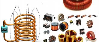
"Spool of thread"
An inductor is an insulated copper wire wound on a solid base. As for insulation, the choice of material is wide - varnish, wire insulation, and fabric. The magnitude of the magnetic flux depends on the area of the cylinder. If you increase the current in the coil, the magnetic field will become larger and vice versa.
If you apply an electric current to a coil, a voltage appears in it opposite to the current voltage, but it suddenly disappears. This kind of voltage is called electromotive force of self-induction. At the moment the voltage is turned on to the coil, the current changes its value from 0 to a certain number. The voltage at this moment also changes its value, according to Ohm’s law:
- I = U : R,
where I characterizes the current strength, U indicates the voltage, R is the coil resistance.
Another special feature of the coil is the following fact: if you open the circuit “coil - current source”, the EMF will be added to the voltage. The current will also initially increase and then decline. This implies the first law of commutation, which states that the current strength in the inductor does not change instantly.
The coil can be divided into two types:
- With magnetic tip. The material of the heart is ferrites and iron. The cores serve to increase inductance.
- With non-magnetic. Used in cases where the inductance is no more than five milliHenry.
The devices differ in appearance and internal structure. Depending on these parameters, the inductance of the coil is determined. The formula is different in each case. For example, for a single-layer coil the inductance will be equal to:
- L = 10µ0ΠN2R2 : 9R + 10l.
But for a multilayer one there is another formula:
- L= µ0N2R2 :2Π(6R + 9l + 10w).
Main conclusions related to the operation of coils:
- On a cylindrical ferrite, the largest inductance occurs in the middle.
- To obtain maximum inductance, it is necessary to wind the turns closely on the coil.
- The smaller the number of turns, the smaller the inductance.
- In a toroidal core, the distance between the turns does not play the role of the coil.
- The inductance value depends on the “turns squared”.
- If inductances are connected in series, then their total value is equal to the sum of the inductances.
- When connecting in parallel, you need to ensure that the inductances are spaced apart on the board. Otherwise, their readings will be incorrect due to the mutual influence of magnetic fields.
Inductance in AC circuit
The passage of electric current through a conductor or coil is accompanied by the appearance of a magnetic field. Let's consider an alternating current electrical circuit, which includes an inductor with a small number of turns of wire of a relatively large cross-section, the active resistance of which can be considered almost equal to zero. Under the influence of e. d.s. generator, an alternating current flows in the circuit, exciting an alternating magnetic flux. This flow crosses the “own” turns of the coil and an electromotive force of self-induction arises in it
The electromotive force of self-induction, according to Lenz's rule, always counteracts the cause that causes it. Since e. d.s. self-induction always counteracts changes in alternating current caused by e. d.s. generator, it prevents the passage of alternating current. In calculations, this is taken into account by inductive reactance, which is designated XL and measured in ohms.
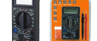
Measuring an inductor with a multimeter
Thus, the inductive reactance of the XL coil depends on the value of e. d.s. self-induction, and therefore it, like e. d.s. self-induction, depends on the rate of change of current in the coil (on frequency ω) and on the inductance of the coil L
XL = ωL,
- where XL is inductive reactance, ohm;
- ω—angular frequency of alternating current, rad/sec;
- L—coil inductance, Hz.
Since the angular frequency of alternating current is ω = 2πf, then the inductive reactance
XL = 2πf L, (59)
where f is the frequency of alternating current, Hz.
Inductance is an idealized element of an electrical circuit in which magnetic field energy is stored. There is no storage of electric field energy or conversion of electrical energy into other types of energy.
Example. A coil with an inductance L = 0.5 H is connected to an alternating current source whose frequency is f = 50 Hz. Determine: 1) the inductive reactance of the coil at frequency f = 50 Hz; 2) the inductive resistance of this coil to alternating current, the frequency of which is f = 800 Hz. Solution. Inductive reactance to alternating current at f = 50 Hz
XL = 2πf L = 2 3.14 50 0.5 = 157 ohms.
At current frequency f = 800 Hz
XL = 2πf L = 2 3.14 800 0.5 = 2512 ohms.
Welding arc inductance
The above example shows that the inductive reactance of a coil increases with increasing frequency of the alternating current flowing through it. As the frequency of the current decreases, the inductive reactance decreases. For direct current, when the current in the coil does not change and the magnetic flux does not cross its turns, e.g. d.s. self-induction does not occur, the inductive reactance of the XL coil is zero. The inductor for direct current is only a resistance
Let's find out how z changes. d.s. self-induction, when alternating current flows through the inductor. It is known that with a constant coil inductance e. d.s. self-induction depends on the rate of change in current strength and it is always directed towards the cause that caused it.
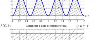
In the first quarter of the period, the current increases from zero to maximum value. The electromotive force of self-induction ec, according to Lenz's rule, prevents an increase in current in the circuit. Therefore, the graph (dashed line) shows that ec at this time has a negative value. In the second quarter of the period, the current in the coil decreases to zero. At this time e. d.s. self-induction changes its direction and increases, preventing the current from decreasing. In the third quarter of the period, the current changes its direction and gradually increases to its maximum value; e. d.s. self-induction has a positive value further, when the current strength decreases, e. d.s. self-induction again changes its direction and again prevents the current from decreasing in the circuit.
Inductance
From the above it follows that the current in the circuit and e. d.s. self-inductions are out of phase. The current is ahead of the e. d.s. self-induction in phase by a quarter of a period or by an angle φ = 90°. It must also be borne in mind that in a circuit with an inductance that does not contain r, at each moment of time the electromotive force of self-induction is directed towards the generator voltage U. In this regard, the voltage and e. d.s. The self-inductances ec are also phase-shifted relative to each other by 180°.
It will be interesting➡ What is electric current, types and conditions of its existence
From the foregoing it follows that in an alternating current circuit containing only inductance, the current lags behind the voltage generated by the generator by an angle φ = 90° (a quarter of a period) and is ahead of e. d.s. self-induction by 90°. We can also say that in an inductive circuit the voltage is 90° ahead of the current in phase. Let's construct a vector diagram of current and voltage for an alternating current circuit with inductive reactance. To do this, let us plot the current vector I horizontally on the scale we have chosen.
To show on a vector diagram that the voltage is ahead of the current in phase by an angle φ = 90°, we plot the voltage vector U upward at an angle of 90°. Ohm's law for a circuit with inductance can be expressed as follows:
It should be emphasized that there is a significant difference between inductive and active resistance to alternating current. When a resistive load is connected to an alternator, energy is irretrievably consumed by the resistive resistance.
If an inductive reactance r = 0 is connected to an alternating current source, then its energy, while the current strength increases, is spent on exciting a magnetic field. Changing this field causes e. d.s. self-induction. When the current decreases, the energy stored in the magnetic field due to the resulting e. d.s. self-induction is returned back to the generator.
- In the first quarter of the period, the current strength in the circuit with inductance increases and the energy of the current source accumulates in the magnetic field. At this time e. d.s. self-induction is directed against voltage.
- When the current reaches its maximum value and begins to decrease in the second quarter of the period, then e.g. d.s. self-induction, changing its direction, tends to maintain the current in the circuit. Under the influence of e. d.s. Self-induction, the energy of the magnetic field returns to the energy source - the generator. At this time, the generator operates in engine mode, converting electrical energy into mechanical energy.
- In the third quarter of the period, the current strength in the circuit under the influence of e. d.s. the generator increases, and at the same time the current flows in the opposite direction. At this time, the energy of the generator is again accumulated in the magnetic field of inductance.
- In the fourth quarter of the period, the current strength in the circuit decreases, and the energy accumulated in the magnetic field under the influence of e. d.s. self-induction is returned to the generator again.
Thus, in the first and third quarter of each period, the alternator spends its energy in a circuit with inductance to create a magnetic field, and in the second and fourth quarter of each period, the energy stored in the magnetic field of the coil as a result of the resulting e. d.s. self-induction, returns back to the generator.
Interesting on the topic: How to check a zener diode.
It follows from this that an inductive load, unlike an active load, on average does not consume the energy generated by the generator, and in a circuit with inductance, energy is “pumped” from the generator to the inductive load and back, i.e., energy fluctuations occur. From the above it follows that inductive reactance is reactive. In a circuit containing reactance, energy oscillates from the generator to the load and back.
It will be interesting➡ How a three-phase rectifier works
Solenoid
This concept refers to a cylindrical winding of wire, which can be wound in one or several layers. The length of the cylinder is significantly greater than the diameter. Due to this feature, when an electric current is supplied, a magnetic field is generated in the cavity of the solenoid. The rate of change of magnetic flux is proportional to the change in current. The solenoid inductance in this case is calculated as follows:
- df : dt = L dl : dt.
This type of coil is also called an electromechanical actuator with a retractable core. In this case, the solenoid is supplied with an external ferromagnetic magnetic circuit - a yoke.
Nowadays, the device can combine hydraulics and electronics. Four models were created on this basis:
- The first is capable of controlling line pressure.
- The second model differs from others in the forced control of clutch locking in torque converters.
- The third model contains pressure regulators responsible for the operation of gear shifting.
- The fourth is controlled hydraulically or by valves.
Necessary formulas for calculations
To find the inductance of the solenoid, the following formula is applied:
- L= µ0n2V,
where µ0 shows the magnetic permeability of the vacuum, n is the number of turns, V is the volume of the solenoid.
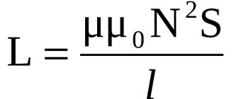
You can also calculate the inductance of the solenoid using another formula:
- L = µ0N2S : l,
where S is the cross-sectional area and l is the length of the solenoid.
To find the inductance of the solenoid, any formula is used that is suitable for solving the given problem.
Calculation methods
There are several basic ways to determine the inductance of a coil. All formulas that will be used in the calculations can be easily found in reference books or on the Internet. The whole calculation process is quite simple and will not be difficult for people with basic mathematical and physical knowledge.
You might be interested in: Features of a two-zone meter
Through current
This calculation is considered the simplest way to determine the inductance of a coil. The formula through current follows from the term itself. What is the inductance of the coil can be determined by the formula: L=Ф/I, where:
- L - circuit inductance (in Henry);
- F is the magnitude of the magnetic flux, measured in webers;
- I is the current strength in the coil (in amperes).
This formula is only suitable for a single-turn circuit. If the coil consists of several turns, then instead of the magnetic flux value, the total flux (total value) is used. When the same magnetic flux passes through all the turns, then to determine the total value it is enough to multiply the value of one of them by the total number.
Finite Length Solenoid
The solenoid is a thin long coil, where the thickness of the winding is significantly less than the diameter. In this case, calculations are carried out using the same formula as through current strength, only the magnitude of the magnetic flux will be determined as follows: Ф=µ0NS/l, where:
- µ0 is the magnetic permeability of the medium, determined from lookup tables (for air, which is taken by default in most calculations, it is equal to 0.00000126 henry/meter);
- N is the number of turns in the coil;
- S is the cross-sectional area of the coil, measured in square meters;
- l is the length of the solenoid in meters.
The self-induction coefficient of the solenoid can also be calculated based on the method for determining the energy of the magnetic flux of the field. This is a simpler option, but it requires some quantities. The formula for finding inductance is L=2W/I 2, where:
- W is the magnetic flux energy, measured in joules;
- I is the current strength in amperes.
Toroidal core coil
In most cases, a toroidal coil is wound on a core made of a material with high magnetic permeability. In this case, to calculate the inductance, you can use the formula for a straight solenoid of infinite length. It has the following form: L=N µ0 µS/2 πr, where:
- N is the number of coil turns;
- µ—relative magnetic permeability;
- µ0—magnetic constant;
- S is the cross-sectional area of the core;
- π is a mathematical constant equal to 3.14;
- r is the average radius of the torus.
You might be interested in Socket with a timer: instructions for use and principle of operation
Long conductor
Most of these quasi-linear conductors have a circular cross-section. In this case, the value of the self-induction coefficient will be determined by the standard formula for approximate calculations: L= µ0l (µelnl/r+ µi/4)/2 π. The following notations are used here:
- l is the length of the conductor in meters;
- r is the radius of the wire cross-section, measured in meters;
- µ0—magnetic constant;
- µi is the relative magnetic permeability characteristic of the material from which the conductor is made;
- µe is the relative magnetic permeability of the external environment (most often the value for vacuum is taken to be 1);
- π—pi number;
- ln is the notation for logarithm.
Work on direct and alternating current
The magnetic field that is created inside the coil is directed along the axis and is equal to:
- B= µ0nI,
where µ0 is the magnetic permeability of the vacuum, n is the number of turns, and I is the current value.
When current moves through the solenoid, the coil stores energy, which is equal to the work required to establish the current. To calculate the inductance in this case, the following formula is used:
- E = LI2 :2,
where L shows the inductance value, and E is the stored energy.
Self-induced emf occurs when the current in the solenoid changes.
When operating on alternating current, an alternating magnetic field appears. The direction of the gravitational force may change or remain unchanged. The first case occurs when using a solenoid as an electromagnet. And the second, when the anchor is made of soft magnetic material. An AC solenoid has a complex resistance that includes the winding resistance and its inductance.
The most common application of solenoids of the first type (direct current) is as a translational power electric drive. The strength depends on the structure of the core and body. Examples of use include the operation of scissors in cutting receipts in cash registers, valves in engines and hydraulic systems, and lock tabs. Solenoids of the second type are used as inductors for induction heating in crucible furnaces.
Oscillatory circuits
The simplest resonant circuit is a series oscillating circuit consisting of connected inductors and a capacitor through which alternating current flows. To determine the inductance of the coil, the formula used is:
- XL = W x L,
where XL shows the reactance of the coil, and W is the circular frequency.
If capacitor reactance is used, the formula will look like this:
Xc = 1 : W x C.
Important characteristics of the oscillatory circuit are the resonant frequency, characteristic impedance and quality factor of the circuit. The first characterizes the frequency where the circuit resistance is active. The second shows how the reactance at the resonant frequency passes between such quantities as the capacitance and inductance of the oscillating circuit. The third characteristic determines the amplitude and width of the amplitude-frequency characteristics (AFC) of the resonance and shows the size of the energy reserve in the circuit compared to energy losses during one oscillation period. In technology, the frequency properties of circuits are assessed using the frequency response. In this case, the circuit is considered as a four-terminal network. When displaying graphs, the value of the circuit voltage transfer coefficient (K) is used. This value shows the ratio of the output voltage to the input. For circuits that do not contain energy sources and various amplifying elements, the coefficient value is not more than one. It tends to zero when the circuit resistance is high at frequencies other than the resonant one. If the resistance value is minimal, then the coefficient is close to unity.
With a parallel oscillatory circuit, two reactive elements with different reactivity strengths are included. Using this type of circuit implies knowing that when connecting elements in parallel, you need to add only their conductivities, but not their resistances. At the resonant frequency, the total conductivity of the circuit is zero, which indicates an infinitely large resistance to alternating current. For a circuit in which capacitance (C), resistance (R) and inductance are connected in parallel, the formula combining them and the quality factor (Q) is as follows:
- Q = R√C : L.
When a parallel circuit operates, during one oscillation period, energy exchange occurs twice between the capacitor and the coil. In this case, a loop current appears that is significantly greater than the current in the external circuit.
Inductance and capacitance in an alternating current circuit
Changes in current, voltage, etc. d.s. in an alternating current circuit occur with the same frequency, but the phases of these changes are, generally speaking, different. Therefore, if the initial phase of the current strength is conventionally taken as zero, then the initial phases of voltage and e. d.s. respectively will have some values of ϕ and ψ. Under this condition, the instantaneous values of current, voltage, etc. d.s. will be expressed by the following formulas:
i = Im sin ωt
u = Uм sin (ϕ + ωt),
e = Ɛm sin (ψ + ωt).
The circuit resistance, which causes irretrievable loss of electrical energy due to the thermal effect of current, is called active. This resistance for low frequency current can be considered equal to the resistance R of the same conductor to direct current and can be found using the formula:
R=(pl/S)(1 + at).
In an alternating current circuit that has only active resistance, for example in incandescent lamps, heating devices, etc., the phase shift between voltage and current is zero, i.e. ϕ = 0. This means that the current and voltage in such a circuit change in the same phases, and the electrical energy is completely spent on the thermal effect of the current.
Connection diagram and diagram
The inclusion of a coil with inductance L in an alternating current circuit manifests itself as an increase in the resistance of the circuit. This is explained by the fact that with alternating current the e is always active in the coil. d.s. self-induction, weakening the current. Resistance XL, which is determined by the phenomenon of self-induction, is called inductive resistance. Since e. d.s. self-inductance is greater, the greater the inductance of the circuit and the faster the current changes, then the inductive reactance is directly proportional to the inductance of the circuit L and the circular frequency of the alternating current ω:
ХL = ωL.
The effect of inductive reactance on the current strength in a circuit is clearly illustrated by the experiment shown in Fig. 26.6. When the ferromagnetic core is lowered into the coil, the lamp goes out, and when it is removed, it lights up again. This is explained by the fact that the inductance of the coil increases greatly when a core is introduced into it. It should be noted that the voltage across the inductive reactance is ahead of the current in phase.
Direct current does not pass through the capacitor, since there is a dielectric between its plates. If a capacitor is connected to a DC circuit, then after charging the capacitor, the current in the circuit will stop.
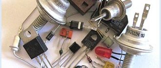
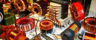
Inductors
Let the capacitor be connected to an alternating current circuit. The charge on the capacitor (q=CU) changes continuously due to voltage changes, so alternating current flows in the circuit. The greater the capacitance of the capacitor and the more often it is recharged, i.e., the greater the frequency of the alternating current, the greater the current strength. The resistance caused by the presence of electrical capacitance in the alternating current circuit is called capacitive reactance Xc. It is inversely proportional to the capacitance C and the angular frequency ω;
Xc = 1/ωС
From a comparison of formulas (26.11) and (26.12) it is clear that inductors represent a very large resistance for high-frequency current and small resistance for low-frequency current, and capacitors - vice versa. The voltage across the capacitive reactance Xa lags in phase with the current. Inductive XL and capacitive XC resistances are called reactive. In the theory of alternating current, it is proven that when inductive and capacitive reactances are connected in series, the total reactance is equal to their difference:
It will be interesting➡ What is the electrical capacity of the capacitor?
X = XL—XC
and has an inductive character for XL > Xc and a capacitive character for XL < Xc.
In conclusion, we note that the average active power of alternating current, showing how much energy per unit time is transferred by electric current to a given section of the circuit, is determined by the formula:
P = IU cos ϕ.
The power expended only on the thermal effect of the current is expressed by the formula:
P = I2R
To increase the active power of alternating current, you need to increase cos ϕ. (Explain why cos ϕ has the greatest value at XL=XC.)
Inductance
Capacitor operation
The device is a two-terminal device of low conductivity and with a variable or constant capacitance value. When the capacitor is not charged, its resistance is close to zero, otherwise it is equal to infinity. If the current source is disconnected from a given element, then it becomes this source until it is discharged. The use of capacitors in electronics is to act as filters that remove interference. This device in power supplies on power circuits is used to recharge the system under heavy loads. This is based on the element's ability to pass alternating current but not constant current. The higher the frequency of the component, the less resistance the capacitor has. As a result, all interference that comes on top of the constant voltage is suppressed through the capacitor.
The resistance of the element depends on the capacitance. Based on this, it would be more correct to install capacitors with different volumes in order to capture various types of interference. Due to the device’s ability to pass direct current only during the charging period, it is used as a timing element in generators or as a pulse-forming element.
Capacitors come in many types. Classification by dielectric type is mainly used, since this parameter determines the stability of the capacitance, insulation resistance, and so on. The systematization for this value is as follows:
- Capacitors with gaseous dielectric.
- Vacuum.
- With liquid dielectric.
- With solid inorganic dielectric.
- With a solid organic dielectric.
- Solid state.
- Electrolytic.
There is a classification of capacitors by purpose (general or special), by the nature of protection from external factors (protected and unprotected, insulated and non-insulated, sealed and sealed), by installation technique (for mounted, printed, surface-mounted, with screw terminals, with snap terminals ). Devices can also be distinguished by their ability to change capacitance:
- Permanent capacitors, that is, whose capacitance always remains constant.
- Trimmers. Their capacity does not change during operation of the equipment, but it can be adjusted one-time or periodically.
- Variables. These are capacitors that allow a change in its capacitance during the operation of the equipment.