To expand the scope of application of the above formulas, we additionally calculated the cross-section of a metal lintel for a brick load-bearing wall on which the floor slabs rest (the results are highlighted in red
) or floor beams (results highlighted
in blue
).
1. Determination of loads per 1 linear meter of lintel:
1.1 From the weight of the masonry:
where, p
in kg/m³ - the density of the material from which the wall is laid, including masonry mortar and plaster.
The density of cement mortar on ordinary quartz sand is up to 2200, which theoretically needs to be taken into account when working with hollow bricks, gypsum blocks and lightweight concrete blocks, but in order not to bother with determining the proportion of mortar in the masonry, you can simply multiply the density of the material by 1.1 or accept the maximum of the following. Note:
structural mechanics considers beams as rods, the height and width of which are not significant compared to the length. Therefore, when determining the distributed load from the weight of the masonry, we multiply the density of the brick by the height and width of the brickwork, obtaining a distributed load of 1 m/p, and if we also multiplied this distributed load by 1 meter of length, we would get the weight of 1 linear meter masonry
- density of solid bricks 1600 - 1900 kg/m³ - density of hollow bricks 1000 - 1450 kg/m³ - density of blocks made of foam concrete, aerated concrete, cellular concrete 300 - 1600 kg/m³ - density of gypsum blocks 900 - 1200 kg/m³
- if the wall above the lintel is made of hollow bricks, then the value p
= 1500 kg/m³ - for gypsum blocks
p
= 1200 kg/m³ - for lightweight concrete blocks - depending on the density of the concrete.
To determine this very density, you need to weigh 1 block (or try to approximately determine the weight of the block by simply lifting it), and then divide the weight by the height, width and thickness of the block. For example, if a block weighs 20 kg and has dimensions of 0.3x0.6x0.1 m, then the density of the block will be 20/(0.3x0.6x0.1) = 1111 kg/m3. In the same way, you can determine the density of the brick. - in all other cases (especially if you do not know the density of the material and cannot determine its density) p
= 1900 kg/m³
b
- wall thickness in meters, for example for a brick wall of two bricks should be taken = 0.51-0.55 m, for walls not finished with wet plaster - 0.51 m, for walls finished with wet plaster only indoors - 0, 53 m, for walls finished with wet plaster both inside and outside - 0.55 m.
h
- the height of the masonry above the lintel. Here questions may immediately arise: what if the height of the masonry above the lintel is 10 meters, does this entire height really need to be taken into account, what cross-section will the lintel have under such a load?
The answer to these questions will be as follows: any load is redistributed in such a way that only the load from the following section of the wall will actively act on the lintel:
those. for calculations, you can take the height h
equal to half the length
L
of the jumper. Of course, in this case, the distributed load will not be uniform, but will vary along the length of the jumper (in this case, you should use the appropriate calculation scheme to determine the maximum bending moment), but let’s not complicate what is already complex. If there is another opening above the design opening, then the height of the masonry in this case will be equal to the distance between the top of the lower opening and the bottom of the upper opening.
For an opening 1.5 m long for a brick wall 2 bricks thick, load q1 = 1900 x 0.53 x 0.5 x 1.5 = 755.3 kg/m
1.2. From the own weight of the metal jumper:
where, n
- number of corners, channels or other profiles,
P
- the own weight of 1 linear meter of an angle or channel, determined by the assortment, there is a small problem here, because how can you know the weight of a rolled profile if its cross-section is only determined, but as a rule, for metal lintels the weight of the lintel does not exceed 1-2% of the weight of the wall or partitions above the lintel, and therefore this weight can be taken into account by a correction factor of 1.1, which takes into account all unaccounted for moments. If you doubt something, you can take the coefficient value equal to 1.2 or even 1.5.
1.3. From wall finishing materials.
Walls can be finished with various materials: dry or wet plaster, ceramic tiles, natural or artificial stone, plastic or aluminum panels, etc. The loads from these finishing materials must be taken into account when calculating. If the walls are simply plastered on one or both sides, then this load has already been taken into account in paragraph 1.1. If you do not yet know how the walls will be finished, or you know, but cannot calculate, then multiply the load from the masonry by a correction factor of 1.2-1.3.
1.4.1. From floor slabs.
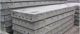
In addition to the fact that the floor slabs themselves weigh quite a bit, you also need to take into account the load from the screed, insulation, flooring, furniture and guests. To somehow simplify this process, you can take the weight of the floor slabs and all the above loads within the range of 800-1000 kg/m². Hollow-core floor slabs weigh about 320 kg/m², up to 100 kg/m² is provided by insulation and screed, and the rest is the load from furniture, guests and other surprises. To determine the load from the floor slabs and everything on the floor slabs, you need to know the length of the floor slabs.
For an opening 1.5 m long for a brick wall 2 bricks thick with hollow core slabs 6 m long, load q4 = 800 x 0.5 x 6 = 2400 kg/m
Thus, the linear design load on the jumper is:
For an opening 1.5 m wide for a brick partition 2 bricks thick, plastered on one side, the total design load is q = 755.3 + 0.015x755.3 + 2400 = 3167 kg/m
1.4.2. From the floor beams.
If the floor beams are located at a distance of 0.5 m from the lintel and above, then the load from the floor and ceiling beams can be considered distributed, and further calculation of the lintel should be carried out as for the lintel on which the floor slabs rest, but if beams and the beams are at a small height from the lintel, then in this case the load will be a point load and when calculating you need to take into account where the floor beams will rest:
Below the beam arrangement diagram is a diagram of the bending moment acting on the beam, in our case the lintel. If the floor beams do not fall on the lintel, then the load from the floor beams is not taken into account at all in the calculation. As can be seen from the above diagrams, the maximum bending moment will act on the lintel if the floor beam is located in the middle:
And the value of the load Q from the floor beam will depend on the distance between the floor beams.
For an opening 1.5 m long for a brick wall with a ceiling over beams 6 m long, with a distance between beams of 1 m, the load Q = 800 x 0.5 x 6 = 2400 kg
2. Selection of section.
2.1.1 The maximum bending moment for a non-cantilever beam on hinged supports, and in our case a lintel, which is subject to a distributed load (in particular, a floor slab), will be in the middle of the beam:
2.1.2 The maximum bending moment for a lintel, which is subject to both distributed (weight of masonry, finishing materials and the lintel itself) and concentrated load (floor beams), will also be in the middle of the beam, but the moment is calculated using a different formula:
Mmax = (q x l 2) / 8 + (Q x l) / 4
Note:
if the ends of the profiles rest on the piers by more than 300 mm, then the beam can be considered not as lying on two supports, but as pinched on both sides, in this case the maximum bending moment will be on the supports:
Mmax = (q x l 2) / 12
, and the bending moment from a concentrated load
Mmax = (Q x l) / 8
.
For an opening 1.5 m long for a brick wall with floor slabs Mmax = (3167 x 1.5 2) / 8 = 890.7 kg m.
For an opening 1.5 m long for a brick wall with floor beams Mmax = (755.3 x 1.1 x 1.5 2) / 8 + (2400 x 1.5)/4 = 233.7 + 900 = 1133, 7 kg m
2.2 Required moment of resistance:
where, Ry
— design resistance of steel. Ry = 2100 kgf/cm² (210 MPa)
Note:
In fact, the calculated resistance depends on the strength class of the steel and can reach a value of 4400, but it is better to take 2100 as the most common.
If two metal profiles are used for the jumper, then the value of Wrequired
must be divided by 2, if there are 3 profiles, then divided by 3 and so on.
For an opening 1.5 m long for a brick wall with a lintel of 2 profiles Wreq = (890.7 x 100) / (2100 x 2) = 21.21 cm 3
For an opening 1.5 m long for a brick wall with a lintel of 2 profiles Wreq = (1133.7 x 100) / (2100 x 2) = 27.0 cm 3
2.4. Well, now everything is simple, first we decide on the type of profile. The jumper can be made from hot-rolled steel angles, equal or unequal flange, I-beam channels, profile pipes. If, for example, the jumper is made from corners, we open the corresponding assortment and see that the value of the moment of resistance is greater than that obtained in the calculation. The main thing here is not to confuse the axes about which the bending moment acts. In assortments, these axes may be called differently. Here the axis relative to which compressive and tensile stresses arise in the cross section is designated as z
, in assortments this axis can be designated as
x
.
But it is not the name that is important, but the principle, when we determined the maximum bending moment acting on the cross section of the beam, then the length of the beam l
was measured along the
x
y
axis , and the width of the beam along the
z
. Thus, no matter what assortment you take, and no matter what the axis is called, the main thing is that the width of the beam is determined along this axis.
For an opening 1.5 m long for a brick wall 2 bricks thick, 2 unequal corners 110 x 70 x 8 mm are sufficient (according to the assortment for such corners Wz = 23.22 cm 3), or 2 channels No. 8P (according to the assortment for such channels Wz = 22.5 cm 3)
For an opening 1.5 m long for a brick wall 2 bricks thick, 2 unequal corners 125 x 80 x 8 mm are sufficient (according to the assortment for such corners Wz = 30.26 cm 3), or 2 channels No. 10P (according to the assortment for such channels Wz = 34.9 cm 3)
Well, then everything depends on the availability of such a profile and the ease of working with it; if such profiles are not available for sale, or it is inconvenient to work with them, then any other profile with a large cross-section is accepted. In addition, for design reasons, instead of 2 corners, it is more convenient to use 4 corners, so that later it will be more convenient to lay brickwork. For example, instead of 2 corners 110x70x8, you can use 4 corners 90x56x5.5.
Note
: The shorter the distance from the slabs or floor beams to the lintel, the more uneven the distribution of the load on the lintel will be. In this regard, it is recommended to take the profile cross-section by 5-20% larger. In addition, profiles of asymmetrical cross-section (unequal and equal-flange corners) are recommended to be connected with metal strips to increase the stability of the corners.
Metal lintels should be supported on the walls by at least 250 mm, and in earthquake-prone areas by at least 400-500 mm.
After selecting the section based on the maximum bending moment, it is advisable to calculate the deflection of the beam; there is even a special formula for this:
f = (5 xqx L 4 ) / (384 x E x Iz)
where, q
- load on the lintel defined in paragraph 1
L
- opening width
E
- modulus of elasticity, for steel
E
= 2 x 10 5 MPa or 2 x 10 10 kg/m²
Iz
- moment of inertia according to the assortment for the selected profile, multiplied by 10 -8 to convert to meters (for 2 profiles this value is logically multiplied by 2), the main thing here is not to make a mistake with the axis.
For a lintel of 2 corners 110 x 70 x 8 mm above the opening 1.5 m deflection f = (5 x 3167 x 1.5 4) / (384 x 2 x 10 10 x 2 x 171.54 x 10 -8) = 0 .003045 m or 0.3 cm
For a lintel of 2 8P channels above a 1.5 m opening, deflection f = (5 x 3167 x 1.5 4) / (384 x 2 x 10 10 x 2 x 89.8 x 10 -8) = 0.0058 m or 0.58 cm
According to the requirements of SNiP 2.01.07-85* “Loads and Impacts”, the maximum deflection value for lintels should not exceed 1/200 of the span, i.e. in our case, the deflection should be no more than 150/200 = 0.75 cm. We have met this condition. If such a deflection of the jumper still does not satisfy you, then you need to select metal profiles of a larger cross-section. That's basically it.
Note
: if the calculation was carried out under the action of a distributed and concentrated load, then it is more convenient to calculate the deflection separately for a distributed and concentrated load, and then add the resulting values.
How to choose lintels in brick walls
In brickwork above window and door openings, it is necessary to lay lintels - usually these are prefabricated reinforced concrete elements according to the standard series 1.038.1-1 or in the case of large spans - according to the 1.225-2 series.
Also, if it is not possible to buy ready-made lintels, you can make reinforced monolithic reinforced concrete lintels or beams from metal elements during construction - it all depends on the size of the opening and the load on the wall. Reinforced concrete lintels according to series 1.038.1-1
- the load on the lintel from its own weight, the weight of the wall and the ceiling (usually for residential buildings in which there are no heavy loads, three types can be distinguished: 1 - the case when the ceiling rests on the wall; 2 - when the wall is self-supporting and the ceiling is not supported; 3 - when the lintel is laid in a brick partition with a thickness of 120 mm).
All jumpers in the series have a designation, for example 2PB18-8, and are presented in the form of a table that indicates the necessary characteristics - dimensions, weight and permissible load on the jumper.
What is encrypted in the name of the jumper 2PB18-8?
PB is a brand. There is a brand PB - block lintels with a width of 120 or 250 mm, which need to be assembled in several pieces depending on the width of the wall and the thickness of the lintel (for a partition 120 mm thick, one lintel is laid, for a wall 380 mm thick - two or three lintels). And there is a brand of PP - these are slab lintels with a width of 380 or 510 mm, designed to cover the entire width of the wall at once.
2 is a code that hides the cross-sectional dimensions of the jumper. So a jumper with the code 1PB has a cross-section of 120x65 mm, where 120 mm is the width of the jumper; code 2PB - 120x140 mm; code 3PB - 120x220 mm; code 4PB - 120x290 mm; code 5PB - 250x220 mm (250 mm - width). Slab lintels have their own values. All this can be viewed in the tables of series 1.038.1-1.
18 - this code contains a jumper length of 1810 mm. If we subtract the depth of support on the wall on both sides by 100 mm, we obtain the maximum opening width for this lintel of 1610 mm.
8 is the load that the jumper can withstand (in this case, 800 kg/m). For example, if it is 8, then the lintel will do an excellent job with a self-supporting wall, if 1 is only for partitions, and starting from 27 and above it can be used for walls on which the ceiling rests.
How to easily select a jumper according to the 1.038.1-1 series? Let's look at examples:
Example 1. An opening in a 120 mm thick brick partition measuring 900 mm. Masonry in summer conditions.
The load on such a jumper is small; three types of jumpers are suitable for partitions:
1PB10-1 (1030 mm long), 1PB13-1 (1290 mm long) and 1PB16-1 (1550 mm long). The minimum depth of support of the lintel on the wall is 100 mm.
Let's determine the length of the jumper: 900 + 100 + 100 = 1100. Thus, a jumper with a length of 1290 mm, brand 1PB13-1, is suitable for us.
Other examples of selecting lintels in partitions are here.
Example 2. A self-supporting wall (the ceiling does not rest on it) 250 mm thick, the height of the wall above the opening is 900 mm, the opening is 1400 mm in size. Masonry in winter conditions.
Since the width of the wall is 250 mm, two lintels are needed across the width of the wall.
In winter conditions, a load from the height of the wall equal to the design span of the lintel is taken on the self-supporting lintel. We preliminary take the design span to be 1400 + 2*100/3 = 1470 mm (here 100 mm is the support depth of the lintel). Because 1470 mm > 900 mm (height of masonry above the lintel), then the value 900 mm will be included in the calculation.
Let's determine the load per 1 linear meter of the lintel:
0.25*0.9*1.8*1.1/2 = 0.23 t/m = 230 kg/m (here 1.8 t/m3 is the weight of the brick, 1.1 is the reliability factor, 2 is number of lintels), and the dead weight of the lintel has not yet been added. Taking into account the fact that it will be necessary to take into account the own weight of the jumper, we will select a load in the series table of 300 kg/m. We select a lintel with index 3. For these lintels, the minimum support depth is 100 mm.
Let's determine the smallest possible length of the jumper: 1400 + 100 + 100 = 1600 mm.
We select a jumper with a length of 1940 mm 2PB19-3.
The self-weight load of this lintel is 81/1.94 = 42 kg/m, so a load-bearing capacity of 300 kg/m is sufficient to support a load of 230 + 42 = 272 kg/m.
More examples of selecting lintels in self-supporting walls are here.
Example 3. A load-bearing wall 380 mm thick supported by a floor span of 3 m on one side, above the opening the wall height is 900 mm, the opening is 1350 mm in size. Masonry in summer conditions.
For this option, you need to select two different jumpers - a load-bearing one on the supporting side of the floor and a less powerful one on the other side. The greater the load-bearing capacity of the lintel, the more expensive it is.
When laying in summer conditions, the load from the lintel is taken from 1/3 of the design span of the lintel. But for the load-bearing lintel, the entire height of the masonry is taken - from the top of the lintel to the bottom of the ceiling, i.e. We will calculate the load from a height of 900 mm. But for a non-load-bearing lintel, we will first take the design span equal to 1350 + 2*100/3 = 1420 mm, then 1420/3 = 470 mm is the height of the masonry, from which we will determine the load for the non-load-bearing lintel.
Let's determine the load per 1 linear meter of the wall from the supporting side of the floor:
1.1*0.3*0.5*3 + 1.2*0.15*0.5*3 + 0.66*1.1*1.8*0.38*0.9 = 1, 21 t/m = 1210 kg/m (here 1.1 and 1.2 are coefficients, 0.3 is the load from 1 sq. m of floor, 0.5*3 is half the floor span, 0.15 is the live load, 0.66*1.1*1.8*0.38*0.9 - two-thirds of the load from the weight of the walls, determined as in example 2). The nearest large load in the series tables is 2800 kg/m. We select a lintel with index 27. For these lintels, the minimum support depth is 230 mm, the width of the lintel is 250 mm.
Let's determine the smallest possible length of the jumper: 1350 + 230 + 230 = 1810 mm.
We select a jumper with a length of 1810 mm 5PB18-27. The load from the weight of this jumper is 250/1.81 = 138 kg/m, the total load on the jumper is 1210 + 138 = 1348 kg/m, which is significantly less than the permissible load of 2800 kg/m - strength is ensured.
The load per 1 linear meter of the wall on the side on which the ceiling does not rest is equal to:
0.33*1.1*1.8*0.38*0.47 = 0.117 t/m = 117 kg/m (here 0.33 is 1/3 of the wall width). The nearest large load is 250 kg/m.
We select a jumper with index 2, for which the support depth is 100 mm.
Let's determine the smallest possible length of the jumper: 1350 + 100 + 100 = 1550 mm.
The maximum length of jumpers with index 2 is 1480 mm, which is less than required. We select the most suitable jumper 2PB19-3 (1940 mm long) or 3PB18-8 (1810 mm long). If we add the dead weight of any of the selected lintels to the resulting load of 223 kg/m, we will be convinced that their load-bearing capacity is sufficient.
Other examples of selecting lintels in load-bearing walls can be found here.
Example 4. A load-bearing wall 380 mm thick supported by a floor span of 6 m on one side and 4.2 m on the other, above the opening the height of the wall is 900 mm, the opening is 1200 mm in size. Masonry in winter conditions.
In winter conditions, the load is taken from a part of the wall whose height is equal to the design span of the lintel. Because The width of the opening is 1200 mm greater than the height of the wall above the opening of 900 mm, then the value of 900 mm will be included in the calculation.
Let's determine the load per 1 linear meter:
1.1*0.3*5.1 + 1.2*0.15*5.1 + 0.68 = 3.3 t/m = 3300 kg/m (here 1.1 and 1.2 are coefficients , 0.3 - load from 1 sq. m of floor, 5.1 = (6+4.2)/2 m - length of collection of load from floor, 0.15 - temporary load, 0.68 = 0.38 * 0 .9*1.8*1.1 t/m - loads from the weight of the wall).
Let's select a slab lintel. The load on it without taking into account its own weight is 3300 kg/m.
The nearest large load is 7200 kg/m. We choose a lintel with index 71. The minimum support depth for such lintels is 170 mm.
Let's determine the length of the jumper: 1200 + 170 + 170 = 1540 mm. We select a slab lintel 3PP16-71 with a length of 1550 mm.
You can download a series of reinforced concrete lintels here:
And finally, a quote from SNiP “Stone and reinforced stone structures” (for those who approach the issue of selecting lintels more carefully:
More articles on the topic of jumpers:
More useful articles:
Attention! To make it easier for you to answer your questions, a new “FREE CONSULTATION” section has been created.
Hello! I would like to clarify one question with you. The floor slab is supported on 2 sides by 120 mm. When calculating the wall, can the load from the slab be taken as follows?
floor design - 195 kg/m2 own weight of the slab - 330 kg/m2 partition weight 260 kg/m2 useful value - 195 kg/m2
. Is it right to take not 3.3? and (3.3-0.12) ?
Well, then I multiply everything by 2 (since the slabs are on 2 sides)
CALCULATION AND SELECTION OF JUMPERS FOR OPENINGS IN WALLS MADE OF SMALL ELEMENTS
Purpose of the lesson: to consolidate theoretical material, learn how to select lintels over window and door openings to brickwork.
Contents of the lesson: on A4 graph paper at a scale of 1:100, draw up a plan diagram for the list of lintels according to the given options, fill out the list of lintels in Form 1 and the specification of precast reinforced concrete elements (Appendix A).
Initial data: diagrams of floor plans (based on materials from practical work No. 1). Jumper types are given in Appendix B.
Procedure for conducting the lesson:
1) Before proceeding with the selection of lintels, it is necessary to complete the floor plan diagrams for the list of lintels. An example plan is shown in Figure 6.1.
To do this, we schematically draw the floor plan of the house with the designation of openings, observing the scale. An example of the circuit is given in Figure 6.2.
2) Assign each opening a position (mark), which is assigned in accordance with the width of the opening and the static function of the wall - load-bearing, self-supporting or non-load-bearing. An example is given in Figure 6.3.
3) Determine the size of the opening: (width and thickness).
4) Select cross-sections of lintels, combining them from several bars or a combination of bars and beams. In load-bearing walls, place “load-bearing” lintels in places where the slab (beam) is supported, and fill the remaining width of the walls with “non-load-bearing” lintels. An example is given in Figure 6.4.
Section diagrams are drawn in table form 2.1 GOST 21.501-93.
Figure 6.1 1st floor plan
Figure 6.2 Layout of the 1st floor
Figure 6.3. Marking of openings
Figure 6.4 Diagram of installation of lintels over openings in external load-bearing brick walls.
For ease of work, keep a count of the required length of jumpers next to the sheet. To do this, we add to the width of the opening the value of the minimum support of the lintels on the wall: “non-load-bearing” lintel + 240 mm (120 mm on each side), “load-bearing” lintel + 500 mm (250 mm on each side). The brands of jumpers are indicated by positions on the section diagram. The “non-load-bearing” lintel takes only the weight of the masonry, and the “load-bearing” lintel takes the weight of the masonry and the floor resting on it.
Calculation of lintels for brick walls
According to the requirements of current standards, when constructing a new opening in an existing stone wall with a width of more than 600 mm, a lintel must be installed above it, the type and design of which are assigned as part of an individually developed design solution.
The most common way to strengthen openings in stone walls is to install a metal lintel consisting of two rolled channels, which are installed above the opening (on both sides, in pre-prepared grooves) and connected to each other using anchor pins with tightened nuts at the ends. This amplification method is implemented according to a standard design solution, the schematic diagrams of which are shown in Fig. 2, 3.
When developing a project for strengthening punched or expanded openings, a significant part of the designer’s working time is spent on performing simple, but quite labor-intensive computational operations related to the selection of the optimal cross-section of the load-bearing metal beams of the designed lintel (performing calculations for groups I and II of limit states).
The tables presented below can significantly simplify and speed up the process of designing metal jumpers, as well as minimize the possibility of errors, which are so difficult to avoid when performing calculations manually.
Method for selecting jumpers using tables
Before you start using the tables below, it is necessary to determine the type of lintel being designed depending on the nature of its static operation and loading pattern. According to this classification criterion, all lintels installed in stone walls can be divided into two large groups: load-bearing and non-load-bearing .
Load-bearing lintels perceive two types of operational loads: pressure from the weight of the brickwork located above the reinforced opening, and the load from the interfloor ceilings. Non-load-bearing lintels support only the weight of the overlying masonry walls. To determine which of the two types the designed jumper belongs to, just look at Fig. 1.
Fig.1.
Diagrams of load-bearing and non-load-bearing lintels in brick walls Thus, the load on the lintels from the floors is not taken into account if they are located above the masonry square with a side equal to the span of the lintel.
The selection of load-bearing elements of metal lintels (channels) is made in accordance with the diagrams presented in Fig. 2-4, according to two known parameters: the width of the designed opening (B) and the thickness of the wall.
Fig.2. Diagram of a metal jumper device for an opening width of less than 2 m
Fig.3. Diagram of a metal jumper device for an opening width of more than 2 m
Fig.4.
Cross section 1-1 (to the diagrams in Fig. 2, 3) Tables for selecting metal jumpers
(click on the image to enlarge)
Table 1. Selection of lintels for walls 250 mm thick
Table 2. Selection of lintels for walls 380 mm thick
Table 3. Selection of lintels for walls 510 mm thick
Table 4. Selection of lintels for walls 640 mm thick
The metal elements of the lintels (rolled beams) are designed to withstand pressure from the overlying walls, the magnitude of which is equivalent to the weight of a masonry column with a height equal to 1/3 of the span of the lintel. The load-bearing lintels, in addition, are also designed for a uniformly distributed linear load from the floors with a value of q = 4.4 t/linear m. For load-bearing lintels installed in walls 250 mm thick (1 brick masonry), the calculated linear load from the floors is taken equal to q = 2.2 t/linear m.
For openings with a width of more than 3 m and loads different from those indicated above, the cross-section of the lintel elements should be taken according to calculation.
Factory solutions
The technology for using lintels in private housing construction has several fundamental differences from the installation adopted in modern and mass construction using cellular aerated concrete. Currently, several types of jumpers are used, which differ in design features and rules of application .
Ready-made version of reinforced gas silicate lintel according to GOST
Ready-made factory aerated silicate (aerated concrete) lintels are ordinary aerated concrete beams with a rectangular cross-section and an internal frame in the form of reinforcement coated with a special anti-corrosion compound.
Arrows on the element indicate the correct direction of installation.
The main advantages are:
- properly reinforced aerated concrete does not crack , does not “float” and does not collapse during long-term use;
- aerated concrete lintels are high-strength, lightweight structures that do not place additional load on the constructed walls and foundation;
- the cellular structure of the aerated concrete lintel is identical to the structure of the building blocks, therefore it does not cause a decrease in thermal efficiency , and as a result there is no need for additional insulation.
Main dimensions of gas silicate jumpers:
- Height - 124 mm;
- Width - 115 mm, 150 mm, 175 mm;
- Length - 1300-3000 mm.
Reinforced concrete lintel layout calculator
We offer a free program for calculating the layout of reinforced concrete lintels over door and window openings in brickwork.
You will only need four parameters that you know well:
– width of the opening to be closed;
– type of wall brick (silicate or ceramic);
– whether the wall is load-bearing (whether the floor slabs rest on it).
Four simple steps:
- 2010 — 2021
- M-ZhBI LLC "KELLE"
- Legal Disclaimer
Order now
Key advantages of steel angle
To make lintels, reinforced concrete monolithic or prefabricated blanks are used. However, for the manufacture of some structures it is recommended to use steel products, including rolled corners.
Among the main advantages of using metal products, the following should be noted:
- simplicity and speed of installation;
- the ability to continue laying a brick or block wall immediately after installing the lintel;
- high levels of strength and durability with the condition of correct selection based on the operational characteristics of the building.

