What factors influence the strength of formwork?
It should be taken into account that too many factors influence the design of the panel fence. For example:
- Calculation of the strength of the material for the construction of the structure. Everyone knows that there are no absolutely identical boards. And their quality depends on the presence of knots, the degree of drying, etc.
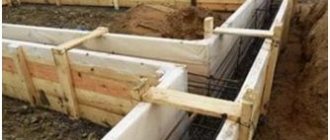
Wooden formwork panel
Correct calculation of the grade and properties of concrete. Concrete can have different consistencies. This directly depends on the ratio of the components that are included in it. You should also take into account the speed of pouring the mixture, the method of compacting it and reinforcing it.- From climatic conditions. In cold and hot weather, boards have different strength indicators. If the boards are dry, they can withstand more pressure than wet ones.
It is also necessary to pay attention to such a concept as formwork deflection. It is different for certain parts of the structure. For example, for the upper part, which is located above ground level, the deflection is no more than 1/400 of the length of the structure. For the lower part - 1/250 of this length. Of course, such results are very difficult to achieve. Therefore, it is better to play it safe and use stronger material.
It is best to make formwork with a certain margin of safety and in no case rely on what may be able to withstand.
A monolithic strip foundation is a very responsible design. Therefore, the calculation of the formwork load is based on certain requirements:
- Reliability and ability to withstand dynamic loads.
- Easy to assemble and disassemble wooden structure.
- No bending of the structure.
- Safety during work.
Formwork: types of structures and requirements for them
Formwork is a structure that is used in the construction of monolithic structures of buildings and structures.
Most often, removable formwork is used in private construction.
Modern formwork is usually divided into two types:
- Removable - this type is a collapsible panel made of wood, metal, plywood or OSB sheets, which are installed when the structure is concreted. After the concrete solution has hardened, the prefabricated structure is dismantled from the surface.
- Permanent formwork - monolithic structures of walls or foundations are not freed from panels after the concrete has completely hardened. Shields become part of the structure, performing additional functions of insulating structures, protecting against moisture, increasing stability, etc.
Additional properties of a fixed structure directly depend on the material from which the shields are made. This type has many advantages, which are expressed in a significant reduction in labor intensity when performing formwork work.
Formwork is used for the installation of monolithic structures of the foundation belt, plinth, walls, ceilings and small building elements. Monolithic house construction, which is gaining significant dimensions, is impossible without the use of formwork structures.
Types of loads on formwork
All loads on the formwork are determined by GOSTR 52085-2003. What should be taken into account when calculating the walls and reinforcements of the shield fence for the foundation?
Pouring the mixture into the formwork
First of all, vertical loads:
- Direct calculation of the weight of the formwork and scaffolding itself. The weight of one cubic meter of timber is: coniferous species - 600 kg, hardwood - 800 kg, plywood - 1000 kg.
- Weight of concrete mixture. One cubic meter of heavy concrete weighs 2500 kg.
- The weight of the fittings is 100 kg per cubic meter.
- The loads of the mixture supply equipment and its compaction are considered equal to 2500 Pa.
The following types of loads, horizontal:
- Wind loads are determined by SNiP 2.01.07-85.
- Using special calculation formulas, the pressure of fresh concrete is determined.
- Loads from the concrete supply mechanism: if the mixture is unloaded through trays - 4000 Pa, from a bucket with a capacity of up to 0.8 cubic meters. m. – 4000 Pa, over 0.8 cubic meters. m. - 6000 Pa, when supplied using a concrete pump - 8000 Pa.
- The load when compacting concrete is 4000 Pa.
The main load is the pressure of the concrete mixture. Since the initial form of concrete is liquid, it exerts hydrostatic pressure on the walls of the structure and depends on the height of the mixture being poured. As the concrete sets, the pressure decreases. Thus, the calculation of the load on the walls depends on the setting speed of the mixture.
Horizontal load
This set of influencing factors includes:
- wind load, whose value is calculated according to SNiP 2.01.07-85;
- indicator of concrete pressure on the walls of the formwork, for the calculation of which the following formula is used:
dB = mV where,
- db – the required indicator of concrete pressure kPa;
- m is the volumetric mass of the concrete mixture, kg/m3;
- B is the height of the concrete layer, m.
Horizontal load on side formwork
| Method of supplying concrete mixture to formwork | Horizontal load on side formwork, kPa |
| Descent along chutes and trunks, as well as directly from concrete pipes | 4 |
| Unloading from buckets with a capacity, m³: from 0.2 to 0.8 sv. 0.8 | 4 6 |
Also considered horizontal are vibration loads that occur when compacting a concrete mixture with special vibrating tools.
How to choose formwork material
Formwork for strip foundations are panels sold from wooden boards. For the manufacture of such a structure, boards made of wood of any species are suitable. For economy, and taking into account the fact that the use of the material is limited, boards of inexpensive species are used. You can use both cut and uncut boards. The shields should be knocked down so that the front part is inside the trench. Watch the video on how to make your own formwork.
Care should be taken to ensure that the surface inside the shield fence is as smooth as possible. When choosing wood for a shield fence, special attention should be paid to its length and thickness. The calculation of the length depends on the size of the foundation trench. The shields should protrude slightly beyond the boundaries of the foundation. Since concrete creates a fairly high pressure on the walls of a wooden structure, the boards are chosen of such a thickness that the boards are able to withstand this load. The optimal board width for installing a fencing structure is considered to be 25–50 mm.
You can use timber of greater thickness, but in no case should you use thin boards. The structure may not withstand, and correcting errors when pouring the foundation is a very labor-intensive and expensive pleasure.
5.2 Loads on formwork from concrete mixture
The load on the formwork from the concrete mixture is determined according to SNiP 3.03.01-87 (Appendix 11) and GOST R 52085-2003.
1. When calculating formwork, scaffolding and fastenings, the following standard loads must be taken:
Vertical loads:
a) own weight of formwork and scaffolding, determined from the drawings. When constructing wooden formworks and scaffolding, the volumetric mass of wood should be taken as follows: for coniferous species - 600 kg/m3, for deciduous species - 800 kg/m3.
b) the mass of freshly laid concrete mixture, accepted for concrete on gravel or crushed stone from hard rocks - 2500 kg/m3, for concrete of other types - according to the actual weight;
c) the weight of the reinforcement should be taken according to the design, and in the absence of design data - 100 kg/m3 of reinforced concrete structure;
d) loads from people and vehicles when calculating the deck, decking and scaffolding elements directly supporting them - 250 kg/m2; decks or flooring when calculating structural elements - 150 kg/m2.
Notes: 1. The deck, decking and directly supporting elements must be checked for concentrated load from the mass of a worker with a load (130 kg), or from the pressure of the wheels of a two-wheeled cart (250 kg), or other concentrated load, depending on the method of supplying the concrete mixture ( but not less than 130 kg).
e) loads from vibration of the concrete mixture - 200 kg/m2 of horizontal surface (taken into account only in the absence of loads according to paragraph “d”);
2. If the width of the deck or deck boards is less than 150 mm, the specified concentrated load is distributed over two adjacent boards.
Horizontal loads:
f) standard wind loads - in accordance with SNiP 2.01.07-85;
g) the pressure of the freshly laid concrete mixture on the side elements of the formwork, determined according to table. 1 appendix 11 from SNiP 3.03.01-87.
Simplified, the value of the maximum hydrostatic pressure of the concrete mixture on the side elements of the formwork can be determined by the formula:
The distribution of pressure along the height of the formwork is adopted by analogy with hydrostatic pressure along a triangular diagram.
Rice. 5.2.1
With a triangular pressure diagram, the resulting pressure can be determined by the formula:
Where
P is the lateral pressure of concrete in kg/m2 at depth h;
γ - volumetric weight of raw concrete in kg/m3 (according to point “b” in most cases γ = 2500 kg/m3);
h is the height of the laid concrete layer in m, but not more than hmax = 1 m (with internal vibration it is allowed to take hmax = 0.75 m).
At a depth h ≥ hmax, the load from lateral pressure is assumed to be constant and equal (see Fig. 5.2.1, b)):
h) loads from vibrations occurring when laying concrete mixture into the formwork of a concrete structure are assumed to be as follows:
— Descent along trays and trunks, as well as directly from concrete pipes — 400 kg/m2;
— Unloading from buckets with a capacity of 0.2 to 0.8 m3 — 400 kg/m2;
— Unloading from buckets with a capacity of over 0.8 m3 — 600 kg/m2;
i) loads from vibration of the concrete mixture - 400 kg/m2 of the vertical surface of the formwork.
3. The selection of the most unfavorable combinations of loads when calculating formwork and supporting scaffolding should be carried out in accordance with Table. 5.2.1.
4. When calculating the elements of formwork and scaffolding according to their bearing capacity, the standard loads specified in paragraph 1 must be multiplied by the overload factors given in table. 5.2.2 of this application.
With the combined action of useful and wind loads, all design loads, except for the own mass, are entered with a coefficient of 0.9.
When calculating formwork and scaffolding elements for deformation, standard loads are taken into account without multiplying by overload factors.
Table 5.2.1
Table 5.2.2
5. The deflection of formwork elements under the influence of perceived loads should not exceed the following values:
1/400 of the span of the formwork element;
1/500 span for floor formwork.
When installing formwork, data from the Master Builder's Handbook (1955), ed. Kazachek G.A., given below:
BASIC DIMENSIONS OF FORMWORK ELEMENTS
(dimensions in cm)
———————————————————————————————————————————————————————————————————
Permissible formwork deviations
During installation, it is necessary to check the deviation of the formwork by level.
As with any other technologies, certain deviations are allowed in the installation of formwork, which are determined by SNiP Sh-15-76.
- During installation of the structure: deviation from the axis - 0.15 cm, from the axis of individual panel structures - 1.1 span lengths.
- Deviations from the vertical: a deviation of 0.5 cm is allowed along the height of one meter, and up to 2 cm throughout the entire height.
- The unevenness of the formwork for a length of up to two meters is 0.3 cm.
- Deviations of collapsible panels in length and width: up to one meter - 0.3 cm, more than one meter - 0.4 cm. Diagonally - 0.5 cm.
- The deviation of the edge of the shield is 0.4 cm.
Hidden deviations include the level of the trench base and the quality of its preparation.
Lateral Load Calculation
The calculation of this value depends on the compaction method. The formula looks like this: P = γH, P = γ(0.27 + 0.78)K1K2, if laying vibrators are used. If they are internal, the limits of use of the formula are:
Calculation and design of formwork
- H ≤ R;
- ν < 0.5;
- ν ≥ 0.5 if H ≥1 m.
If styling is done using external vibrators, the limits for using the formula are as follows:
- H ≤ 2R1
- ν < 4.5
- ν > 4.5 if H > 2 m.
Here P is the maximum pressure of the solution in kPa, γ is the volume-weight indicators of the concrete pouring in kg/m3, N is the height of the material layer in meters, ν is the speed of pouring the material, m/h, R, R1 are the operating radii of the internal and external vibrator in meters. If the fill is inactive, rigid, with a cone settlement parameter from zero to two cm, K1 takes the value 0.8. If from 4 to 6 cm – K1=1. When the cone draft is from 8 to 12 cm, K1 = 1.2.
K2 depends on the temperature of the composition and takes the value 1.15 at temperatures from 5 to 7 °C, 1 at temperatures from 12 to 17, 0.85 at temperatures from 28 to 32 degrees Celsius.
Calculation of load on formwork
Reduced adhesion of concrete to formwork
Problems may arise when dismantling the panel structure due to the adhesion of concrete to the material used. Several factors influence the adhesion force: shrinkage of the mixture, unevenness and porosity of the material. Concrete adheres more to wood and metal, less to plastic. In order to reduce coupling, it is necessary to take into account some factors to correctly calculate this value:
- The surface of the structure is formed from smooth materials.
- After installing the formwork and before pouring concrete, a special lubricant is applied to the inner surface of the structure.
The use of lubricants sharply reduces the adhesion of the mixture to the formwork. For example, when treating steel formwork with lubricant, the adhesion to concrete after 24 hours decreases by 4–5 times.
Vertical load
This concept means the total load exerted on the supporting elements of vertical formwork systems by structural elements, pouring mixture and other operating factors. The design components of the vertical load include:
- The total weight of the complex of formwork elements. The weight of each component part is indicated in the technical documentation. When using wooden formwork, the weight is calculated according to the constants approved in SNIP: 800 kg/cub.m. – for hardwood, 600 kg/cub.m. – for coniferous wood varieties.
- Mass of reinforcing elements. Indicated in the design data or calculated using a constant for reinforced concrete structures equal to 100 kg/m3 (in the absence of exact data).
- The load exerted by transport and human labor. The nomenclature value of this indicator may differ for the calculation of specific formwork elements or their complex. In this case, values of 1.5 kPa and 2.5 kPa are considered, respectively.
- Concrete mass - calculated by the actual weight of the components or using nomenclature data, for concrete mixtures with crushed stone or gravel (2500 kg/cub.m.).