About the types of products
Products are classified according to several parameters.
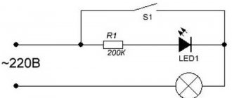
Based on the position of the locking element in the absence of voltage on the coil, the following are distinguished:
- Normally open, or BUT. The passage for liquid or gas is open, but when voltage is applied, it closes.
- Normally closed, or NC. The passage for the medium is blocked, and when voltage is applied it opens.
Some models are produced as universal ones, and normally the position of the locking element is adjusted during installation and connection to the control network. Such switched devices are called bistable.
Depending on the working environment, shut-off valves are produced for:
- Air.
- Water.
- Pair.
- Active media
- Fuels and lubricants.
Devices for working in radioactive environments are distinguished by a special selection of materials with increased radiation resistance. The vacuum solenoid valve must provide particularly high tightness
Based on the characteristics of the external environment, the design of the device can be:
- Normal
- For wet areas.
- Heat resistant (for high temperatures).
- Frost-resistant (for extremely low temperatures).
- Explosion-proof. Such devices should not spark when turned on or off. For this purpose, they use special design solutions and materials.
According to the type of supply voltage, coils are divided into
- AC, high voltage. They develop high forces and are used on main pipelines of high pressure and large diameters.
- Direct current, low voltage. Used on pipes of small cross-section and low pressure.
There is a separate class of high pressure solenoid shut-off valves. They are called cutoffs. They are designed to instantly shut off pipelines or seal containers in the event of abnormal or emergency situations.
And finally, according to the type of functioning, valves are divided into
- One-way. This type of valve has only an inlet pipe. Usually they are normally closed and open the way for water or air flow to the external environment. Used as safety precautions.
- Two-way. The most common type has inlet and outlet pipes and is mounted in a pipeline break. They are used to control the flow in one of the circuits of the pipeline system.
- Three-way. They may have one inlet and two outlets, or two inlets and one outlet.
Three-way valves of the first type are used to redirect flows from one circuit to another (for example, in a heating system). This allows you to maintain the temperature of the working environment constant without changing the operating parameters of the heat source. Devices of the second type are used to mix two streams having different temperatures. A typical example is the single-lever ball mixer in the kitchen or bathroom.
Indirect acting solenoids
This type of solenoid is more complex and will take more time to explain the mechanism of its operation. Simply put, an indirect acting solenoid consists of two valves connected into one mechanism. The main valve is a spool that works according to the principle described above, the second mechanism used is the pilot valve, which is located between the spool and the electromagnet. The control valve is a small direct-acting solenoid that activates the push of the large spool. Please note that the solenoid shown in this image is a direct acting solenoid as it acts directly on the control valve, but the entire assembly is an indirect acting solenoid.
The main difference between direct acting and indirect acting solenoids is how they interact with the mechanical parts of the marker. Direct acting solenoids work directly with the elements of the marker mechanism. Indirect acting solenoids use air flow to control the spool. The main reason for the existence of indirect acting solenoids is their incredibly low power consumption compared to direct acting solenoids. For example, if a direct acting solenoid requires 4 watts to affect a mechanism, then an indirect acting solenoid only needs 0.5 watts to effect the same effect.
Solenoid operation diagram.
Next, solenoids are divided according to the number of threads. To function, the solenoid must have at least one hole through which air enters the solenoid, one hole through which air enters the mechanism, and one hole through which air is released. But in most cases, a design is used with two holes for supplying air to the marker mechanism and two air release holes. Currently, there are mainly three main types of solenoids in use:
- Four way spool valve. This type is used in most all-electro-pneumatic markers, where air is used to move the piston back and forth. For example Ego, Angel, Shocker, Dye Matrix, etc. The incorrectly named three way valve on cockers is also an example of a four-way piston.
- Three-way spool, closed when at rest (3-way spool normally closed). This is a three-flow valve that supplies air when voltage is applied to it. When this solenoid is at rest, it does not supply any pressure, for example pVI Shocker, Invert Mini.
- Three-way spool, open when at rest (3-way spool normally open). This is a three-flow valve that supplies pressure at rest, and shuts off the air flow when voltage is applied to it, such as Ion.
The control valve in the solenoid is always three-flow, closed at rest. When voltage is applied to the solenoid, the control valve opens and supplies air in order to move the spool, which, in turn, can be either three-flow or four-flow.
Each indirect acting solenoid is divided into three segments: coil, pilot and spool. The coil is the only electromagnetic part of the entire mechanism. It consists of copper wire wrapped around a metal casing, inside which there is a metal rod, which is the opposite magnetic component of the valve. The rod is made of steel and has a spring at one end. At the opposite end of the solenoid is the spool, which is the valve and the main moving part of the solenoid. Spools are usually made of brass or aluminum depending on the manufacturer.
It will be interesting➡ What is an inductor and why is it sometimes called a choke
There are also various gaskets on the spool to redirect air flow. And finally, the last part of the solenoid is the control valve, which is the “mediator” between the movement of the coil rod and the spool. The main component for a control valve is a round piston that moves the spool to the open position. The piston is a small plastic disc with a gasket around it. Behind the piston is a small actuator, a piece to hold the actuator in place, and a small plug located inside the actuator. Most of these components, like the control valve body, are made of polymers to improve sliding and sealing.
Interesting material for familiarization: what are variastors.
In conclusion of the article, what is dwell? This is the time during which voltage is applied to the solenoid (respectively, the path of the marker bolt to the forward position + the time that the bolt is in the forward position, releasing air). If you lower the dwell setting too much, you will have to compensate for the shorter time the bolt stays in the forward position by increasing the operating pressure of the marker, which will not be beneficial for your marker. A too high value of the dwell parameter will lead to excessive air consumption, battery charge and greater wear of the solenoid itself.
Two identical solenoids.
Some installation recommendations
To install the valve, you must first prepare the pipeline system and clean it of dirt and dust to avoid premature failure of the device. A special filter is installed to help avoid the entry of large foreign particles.
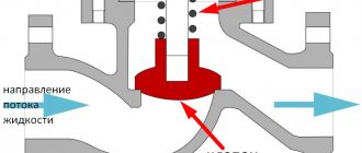
Figure 8. Valve installation
The arrow indicator fixed on the device body must be identical to the direction of movement of the medium flow. Otherwise, it may also cause serious damage. You will also need to secure the ends of the valves as tightly as possible. In practice, it is important to use two wrenches. Installation is carried out by welding or using connections that require disassembly.
It is imperative to isolate the areas where the connection will be made. For this purpose, sealant or ordinary electrical tape is used.
Before connecting the device, it is important to check the specifications of the coils for the requirements
PWM, VFS and "proportional"
In the nineties, the design of solenoids became even more complex. Now the solenoids were required not only to open and close the oil flow, but also to provide smooth pressure control.
The operation of these solenoids became similar to the operation of a valve, rather than a faucet. Now there were not two provisions, but many. Depending on the command of the electronic control unit, they are able to smoothly open or close the channel, according to the calculated curve.
Instead of plungers, balls or spools are now used, 4Way and 5Way appear.
Proportional solenoid
Toyota's transmission subsidiary, Aisin, creates its own solenoid design, which it calls “proportional.”
This much more complex and technologically advanced device now includes ports that were previously part of the hydraulic valve plate and are controlled by a spool plunger to open or close them. The channels, which were previously located inside the hydraulic plate and were actively worn out by abrasive treatment with metal particles and debris in the oil, have now become part of the solenoid. If they wear out, there is no need to replace or restore the entire valve body - just change the solenoid itself. The service life of the hydraulic plate has increased significantly, and the most obvious problem of all modern automatic transmissions has been solved. The “proportional solenoids” themselves, of course, do not last very long, but they are also consumables - their replacement is very simple, you can do it yourself, and they are quite inexpensive in comparison with the valve plate. After 5–6 years, it is necessary to check their performance.
In modern automatic transmissions, these solenoids are also adjacent to conventional, “open-closed” types, but proportional ones do almost all the work, providing control of 4-5 oil flows each.
VFS or electric ball valves are widely used by ZF. They have a simpler and cheaper design. Instead of difficult-to-manufacture elements, here the role of a valve is played by a small steel ball.
VFS solenoid automatic transmission
However, controlling such simple elements requires a very complex control system. The electronic control unit requires very precise feedback and is forced to constantly adapt to increasing pressure losses due to gradual wear of the valve. Fine tuning and constantly changing parameters make the operation of such an automatic transmission very capricious. The service life of these solenoids rarely exceeds five years; it is better to check them after 2–3 years of operation.
PWM Made from stronger and more reliable materials, they are more expensive. Trying to make them more reliable is the solution to the biggest problem with modern automatic transmissions. When opening and closing the flow in the operation of the solenoid, at some points in time a very small gap inevitably formed, through which oil filled with debris and metal particles rushed at great speed. With a large cross-section, debris could easily walk inside the oil flows and be pushed away from the walls of the channel, but when it was reduced, large pieces of debris were literally dragged under pressure along its walls. Which led to its wear and tear. In PWM solenoids, the weakest points have been strengthened.
PWM solenoid
If earlier automatic transmission designs were simpler, more reliable and could run on liquids that hardly resembled oil, now modern automatic transmissions are much more “gentle.” Previously, hydraulic blocks were made of cast iron, but now they are made of soft, lightweight aluminum. Due to attempts to squeeze out maximum efficiency, reduce losses on the torque converter, reduce fuel consumption, increase the dynamics and comfort of the car, all automatic transmission mechanisms began to work much more accurately and loaded. Which inevitably led to increased wear of all gearbox mechanisms and rapid contamination of the oil with their remains. The filter elements have also been modernized, but they are not perfect. If in a modern automatic transmission you do not change the oil as it becomes dirty, it acquires the properties of sandpaper, which is constantly driven through all the insides of the machine at high speed. And this makes him feel completely unwell.
Typical problems
Very often, solenoids become unusable due to burnout of the electrical winding. Carbon deposits appear on the plunger. It becomes clogged with very fine dust from various consumables and components. In such cases, the spool valve begins to jam either at operating oil temperature or “cold”. This can be easily corrected by washing in special solvents. Craftsmen use ultrasound or alternating current to clean parts. In some cases, the friction lining wears down to the adhesive substance. Then glue is added to the soot along with the dust. This will significantly complicate the repair procedure.
We recommend: Electrolyte for batteries
A popular cause of failure is also wear and tear on the components of the solenoid itself. It could be:
- manifold;
- bushings;
- valve;
- plunger;
- ball.
Most often, from my own experience, I can say that the plunger itself becomes clogged with products from wear of the clutches. Then switching problems appear. The carbon deposits that appear on the surface abrade the rubbing surfaces of valves and bushings. Bronze bushings wear out very often. There are special kits for replacing bushings yourself. They significantly extend the service life.
Solenoids have their own service life. It is calculated by the number of openings and closings. This figure falls within the range of 300,000 to 400,000 cycles. When exactly this happens does not always depend on mileage, but largely depends on the operation of the electronic control unit when you press the gas pedal. Some gearboxes have an operating mechanism in which some work an order of magnitude more intensely than others. As a result, they will use up the resource earlier.
Another common cause of breakdown is various mechanical damage (cracks) in the housing. Maybe the spring itself is not elastic enough. Or there was a break in the electrical winding.
Valve check
The carburetor valve should be checked in the following modes:
- Idling. After starting, increase the speed to 2100 and listen to the carburetor. A sharp characteristic sound should be heard indicating the shutter is closing. Next, smoothly reduce the speed to 1900; an opening click should be heard.
- Engine braking. You need to let off the gas without changing gear. In this case, a working valve will not work, even if the speed has dropped to 1900. If a click is heard, the device is faulty.
- After stopping the engine. If, when the ignition is turned off, spontaneous outbreaks of the detonating working mixture continue in the cylinders, the engine jerks and vibrates - this means that the valve does not shut off the fuel supply to the chambers and further to the cylinders.
- If you pull the solenoid valve power wire out of the connector while the engine is running, the engine should stall. If it continues to work, it means the valve is faulty.
In addition to ways to check the solenoid valve “on the go,” you can unscrew the valve from the carburetor body and try to apply voltage to it from the battery. One wire from the battery is connected to the contact block, the other to the body of the device. When voltage is applied, the valve should click and pull the needle inward.
After the circuit opens, another click is heard and the return spring retracts the needle. At the same time, you can check whether the parts of the device are contaminated with resinous deposits. They need to be soaked in gasoline and removed with a soft cloth.
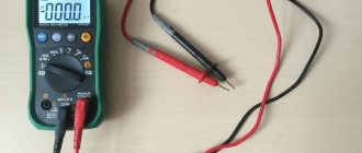
It is also necessary to check whether control voltage is supplied to the contacts. Its normal value is 10.5-14.4 volts. If there is voltage on the control unit, but not on the contact, it means the wire is faulty. It needs to be repaired or replaced.
If there is no voltage at the control unit connector, then most likely the unit itself is faulty. It is checked by connecting the valve to the battery with another temporary wire. A voltmeter or test light is connected to the terminal of the control unit that controls the valve.
Next, you should start the engine. When the speed reaches 900 rpm, the light should flash, and at 2100 rpm it should go out. If you reduce the defense to 1900 rpm, it will flare up again. This behavior of the light bulb means the control unit is working properly.
If the light does not light up or go out at all, and also turns on and off at different speeds, the control unit is subject to in-depth testing and, possibly, replacement.
Functions of modern solenoids
EPC solenoid. Line pressure solenoid. In the design of modern automatic transmissions, the linear pressure solenoid is the most important. It is usually located first in the hydraulic plate. All oil flow passes through the line pressure solenoid. If the line pressure solenoid is faulty, then increased pressure may be supplied to the box, which will quickly destroy many of its mechanisms. The solenoid is heavily loaded and usually fails faster than its brothers.
TCC solenoid. Torque converter clutch lock-up solenoid. It controls the torque converter lock-up, which improves efficiency and increases the vehicle's acceleration performance. In modern automatic transmissions, this solenoid is usually the weakest - the hottest and dirtiest oil flows through it. Although this depends on the character of the driver - for people who love a quiet and smooth ride, this solenoid practically does not work.
Shift solenoid. Shift solenoid. A complex and large solenoid with many channels, responsible for shifting gears.
Control solenoid. Controls valves like transistors in electrical circuits.
Slip mode solenoid. Responsible for the “smoothness” of gear shifting, switching the automatic transmission to the “slip” mode.
Automatic transmission solenoid
Cooling solenoid. Responsible for oil cooling and access to the radiator.
Advantages of solenoid valves for water
The main advantage of the device is the ability to remotely and quickly regulate the flow of the working environment. Without electromagnetic shutters, the operation of complex technological installations and simple household appliances, such as a coffee maker and washing machine, becomes impossible.
In addition, the electric drive allows:
- Connect the solenoid valve to a centralized and automated control system. This greatly increases the accuracy and efficiency of parameter adjustments compared to manual control.
- Reduce labor costs for managing technological processes.
- Increase production safety and eliminate the operator’s exposure to harmful factors in the production environment.
- Increase the efficiency of household appliances and production plants through precise and fast control of the flow of working media and their parameters.
This ensures high equipment reliability, minimal wear and a long service life.
The disadvantage of this type of device is the inability to smoothly adjust the degree of shutter opening. Only two positions are provided: “open” and “closed”.
What are there
There are several common classifications. The first is based on the proportional indicators of moves and their number. Kinds:
Constipated;
Fig 4. Shut-off
- Distributing;
- Switching.
Fig 5. Switching
The second type of classification depends on how the mechanism and valves are located:
- Bistable;
- Normally open (if voltage is applied, they close automatically);
- Normally closed (closed in operating condition and opens after voltage is applied).
BS (bistable) has gained the greatest popularity because it is controlled using an electrical impulse, the transmission of which occurs through the remote control. It is used to determine the position of the device: closed or open.
Depending on the material used for seals and membranes, there are:
- EPDM;
- FKM;
- NBR;
- PTFE;
- TEFLON;
- VMQ.
They are distinguished by high elasticity rates using rare manufacturing technologies and chemical compositions. The latest models contain rubber and silicone. Thanks to the improved composition, endurance increases to 250 degrees.
Depending on the voltage withstand, valves can be divided into:
- With alternating current AC;
- With constant current AD.
Each type allows an error of +10%. The latest standard developed is designated IP65. According to the classification we can indicate:
- Pilot (impact is not carried out directly).
Figure 6. Pilot
- They act directly.
Fig 7. Straight
Such valves operate in the presence of minimal pressure or in its absence. As a rule, it is used for household needs, storage or drain receivers. The pilot version has an automatic control element. The mechanism operates with minimal differences in pressure.
Solenoid operating principle
The most primitive solenoid design is a coil that creates a magnetic field. The devices we call solenoids consist of a coil and a moving core of iron or other material. When current is applied to the coil, the core is retracted and causes the mechanical object connected to the core to move. A simple solenoid is shown below:
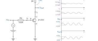
To drive the core, voltage is applied to the coil. Since the inductive reactance of the coil is quite large, to speed up the response processes, an increased voltage is applied to the coil. The pulling force of the core is proportional to the current.
Much less current is required to keep the mechanical device in the core. If the current in the coil is not reduced after the mechanical device has reached its end point, this will cause the solenoid to heat up significantly more.
To solve this problem, you can use a constant current driver. The current can be controlled over time to ensure minimal heat loss while maintaining the maximum required holding torque.
What are the consequences?
Many car owners are often concerned with the question of whether it is possible to ignore an exhausted solenoid valve and what the consequences of this are, if there is any alternative or if they need to urgently go to a service station.
Let's go in order. Essentially, the electrovalves open the channel of the blocked clutch of the clutches. Of course, the speed can be switched with jerks, it’s not scary, especially since you know that this is a faulty valve. But at the same time, we must also not forget that the channel itself may not be fully open or closed, which is akin to a clutch not being fully released in a manual transmission.
This will create a lack of pressure and operation in dry mode, which will cause combustion of both oil and clutches, and the production of all iron and bushings will begin. Ultimately, you will get the death of the solenoids due to their operation at full cross-section.
Magnetic field of the solenoid. The formula, the essence of the phenomenon.
The magnetic field of a solenoid is a superposition of individual fields that are created by each individual turn. The same current flows through all turns. The axes of all turns lie on the same line. The solenoid is an inductor coil having a cylindrical shape. This coil is wound from conductive wire. In this case, the turns are laid tightly to each other and have the same direction. In this case, it is believed that the length of the coil significantly exceeds the diameter of the turns.Let's look at the magnetic induction created by each turn. It can be seen that the induction inside each turn is directed in the same direction. If you look at the center of the coil, then the induction from its edges will add up. In this case, the magnetic field induction between two adjacent turns is directed in the opposite direction. Since it is created by the same current, it is compensated.
Figure 1 — Field created by individual turns of the solenoid
If the turns of the solenoid are wound tightly enough, then between all the turns the counter-field will be compensated, and inside the turns the individual fields will be added into one common one. The lines of this field will pass inside the solenoid and cover it outside.
If you examine the magnetic field inside the solenoid by any means, for example, using iron filings, you can conclude that it is homogeneous. The magnetic field lines in this region are parallel straight lines. Not only are they parallel to themselves, but they are also parallel to the axis of the solenoid. Going beyond the aisles of the solenoid, they bend and close outside the coil.
Figure 2 - Field created by the solenoid
It can be seen from the figure that the field created by the solenoid is similar to the field created by a permanent bar magnet. At one end, the power lines exit the solenoid and this end is similar to the north pole of a permanent magnet. And they enter the other, and this end corresponds to the south pole. The difference is that the field is also present inside the solenoid. And if you conduct an experiment with iron filings, they will be drawn into the space between the turns.
But if a wooden core or a core made of any other non-magnetic material is inserted inside the solenoid, then when conducting an experiment with iron filings, the field pattern of the permanent magnet and the solenoid will be identical. Since the wooden core will not distort the power lines, but will not allow sawdust to penetrate inside the coil.
Figure 3 — Picture of the field of a permanent bar magnet
Several methods can be used to determine the solenoid poles. For example, the simplest one is to use a magnetic needle. It will be attracted to the opposite pole of the magnet. If the direction of the current in the coil is known, the poles can be determined using the right-hand screw rule. If you rotate the head of the right screw in the direction of the current, the translational movement will indicate the direction of the field in the solenoid. And knowing that the field is directed from the north pole to the south, you can determine which pole is located.
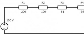
To find the magnetic induction modulus of a single-layer solenoid, you can use the formula.
Formula 1 - Solenoid Magnetic Induction Module
Where N is the number of turns of the solenoid
l solenoid length
n number of turns per unit length
I Solenoid current
Mu is the magnetic permeability of the medium inside the solenoid
Mu0 magnetic constant
Watch video: current coil
Reasons for failure of solenoids in automatic transmissions, diagnostic difficulties
Despite their durability and reliability, automatic transmission solenoids sometimes fail, become deformed, and break.
The most common causes of solenoid failures:
- Accumulation of harmful oil deposits on metal rods.
- Lack of response to electrical signals (the rod gets stuck and does not extend).
- Core jamming.
The use of cheap, low-quality transmission oil or failure to meet the deadlines for a complete service replacement of the lubricant leads to the final destruction of the functionality of the solenoids in automatic transmissions. Wear products included in the working fluids are gradually deposited on the surface of the magnetized rod.
Such a breakdown is difficult to detect during diagnosis. To avoid failures in transmission control, it is recommended to fill the crankcase with transmission oil of the appropriate quality, and also not to ignore the car manufacturers’ recommendations on regular replacement of lubricant.
Service companies carry out computer diagnostics of automatic transmissions, including solenoids. If necessary, unsuitable solenoid valves are replaced here with new mechanisms. Masters of specialized points can instruct in detail how to check the performance of solenoids.
Simple drivers for solenoids
The easiest way to control a solenoid is to turn the current on and off. This is often done using a low side MOSFET switch and a current protection diode (picture below). In this circuit, the current is limited only by the supply voltage and the constant resistance of the solenoid.
The electromechanical performance of a simple solenoid actuator is limited. Since full voltage and current are applied 100% of the time, the pull-in current is limited by the constant power dissipation of the solenoid. The large inductance of the coil limits the rate of current rise when the solenoid is turned on.
The test measured the movement, voltage and current of a solenoid activated using a simple switch (picture below). In this case, the solenoid (15 ohm rated at 12 V) took 30 ms to turn on to drive the mechanical drive and dissipate 10 W of power.
If you are wondering about the "valley" in the current waveform, this decrease in current is due to the back EMF created by the moving solenoid core. The back EMF increases as the core accelerates until the solenoid retracts and stops.
How to test the starter solenoid?
A starter is a device that spins the shaft of an internal combustion engine to start it.
The starter solenoid is an electromechanical device for shifting the clutch gear to the engine or flywheel. When current is applied to the solenoid terminals, the internal magnetic windings become energized. This creates a magnetic field that acts on the internal piston, which in turn moves the lever and thereby fires it. The solenoid plunger completes the circuit between the battery and the unit. Modern solenoids in the unit are connected directly to the motor. In most cases, if the solenoid breaks, you have to replace the entire device.
The solenoids are attached to the starter itself. Test them with an adapter cable: if everything is bad, then replace the starter. Let's diagnose the starter.
Find the starter solenoid
To make repairs safely and efficiently, you will need some tools:
- repair manual;
- jack and jack;
- jumpers or remote engine starter;
- protective gloves;
- protective glasses.
Step 1: Raise the car with a jack. After lifting, be sure to secure the vehicle on racks.
Step 2: Locate the solenoid. The mechanism itself is usually located in a bell-shaped housing at the bottom of the engine. The solenoid is located in the upper part of the housing.
Test the starter
Step 1: Locate the ignition terminal. It is often equipped with an electrical connector and is the smallest size of all terminals.
Step 2: Attach jumpers. First connect them to the device terminal. Then quickly touch the other end of the jumper cable to the positive battery terminal of the jumper battery.
If the solenoid and starter are working, it will start the engine without any problems. The safest way to perform this test is to use a remote unit. The connection principle is the same, but it has a special button for starting the device independently.
Comment. The battery terminal is constantly under voltage, so do not touch it under any circumstances, as this can lead to extremely unpleasant consequences for your health.
Step 3: Lower the vehicle. Once the check is completed and you have made all the repairs, return the car from heaven to earth using the same jack.
If you were unable to diagnose the malfunction yourself, then contact a professional repair service for starters and generators - the AGS company by phone.
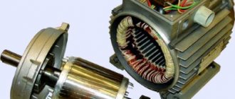
Description and principle of operation of the solenoid
A linear solenoid operates on the same basic principle as the electromechanical relay described in the previous lesson, and just like relays, they can also be switched and controlled using transistors or MOSFETs. A linear solenoid is an electromagnetic device that converts electrical energy into a mechanical pushing or pulling force or movement.
A linear solenoid basically consists of an electrical coil wound around a cylindrical tube with a ferromagnetic drive or "plunger" that can freely move or slide the "IN" and "OUT" in the coil housing. Solenoids can be used to electrically open doors and latches, open or close valves, move and control robotic limbs and machinery, and even turn on electrical switches just by applying power to its coil.
Solenoids are available in a variety of formats, with the most common types being the linear solenoid, also known as linear electromechanical actuator (LEMA) and rotary solenoid. You can find and purchase these types and more on Aliexpress.
Both types of solenoids, linear and rotary, are available in hold (constant voltage) or latch (ON-OFF pulse) form, with latch types used in energized or power-off applications. Linear solenoids can also be designed for proportional motion control, where the position of the plunger is proportional to the power input.
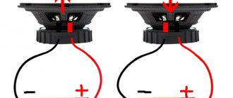
When electric current flows through a conductor, it generates a magnetic field, and the direction of this magnetic field relative to its north and south poles is determined by the direction of current flow within the wire. This coil of wire becomes an "electromagnet" with its own north and south poles, just like a permanent magnet.
The strength of this magnetic field can be increased or decreased either by controlling the amount of current flowing through the coil or by changing the number of turns or loops the coil has. An example of an "electromagnet" is given below.
Solenoid Duty Cycle
Another more practical way of reducing the heat generated by the solenoid coil is to use "intermittent duty cycle". Intermittent duty cycle means that the coil is switched ON and OFF repeatedly at a suitable frequency to activate the plunger mechanism but prevent it from de-energizing during the OFF period. Intermittent switching of the duty cycle is a very effective way of reducing the total power consumed by the coil.
The duty cycle (% ED) of a solenoid is the portion of the "ON" time when the solenoid is energized, and is the ratio of the "ON" time to the total "ON" and "OFF" times for one complete cycle of operation. In other words, the cycle time is equal to the on time plus the off time. The duty cycle is expressed as a percentage, for example:
Then if the solenoid is on or on for 30 seconds and then off for 90 seconds before turning on again, one full cycle, the total on/off cycle time will be 120 seconds, (30 + 90) so the duty cycle of the solenoids will be calculated as 30/120 sec or 25%. This means that you can determine the maximum on time of the solenoids if you know the duty cycle and off time values.
For example, the off time is 15 seconds, the duty cycle is 40%, so the on time is 10 seconds. A solenoid with a 100% duty cycle rating means it has a constant voltage rating and can therefore be left on or constantly on without overheating or damage. In this lesson on solenoids, we looked at both the linear solenoid and the rotary solenoid as an electromechanical actuator that can be used as an output device to control a physical process. In the next lesson we will continue to look at output devices called actuators and the device that again converts the electrical signal into a corresponding rotational motion using electromagnetism. The type of output device we will look at in the next lesson is the DC motor.
Material on the topic: What is a time relay.
Solenoid in package
DIY solenoid motor
The best material for reels is considered to be textolite or hardwood. For winding, PEL-1 wire with a diameter of 0.2-0.3 mm is used. Winding is carried out in an amount of 8-10 thousand turns, ensuring the resistance of each coil is within 200-400 Ohms. After winding every 500 turns, thin paper spacers are made, and so on until the frame is completely filled.
Mild steel is used to make the plunger. Cranks can be made from bicycle spokes. The upper head must be made in the form of a small ring-shaped ear with the required internal diameter. The lower head is equipped with a special grip for mounting on the crankshaft journal. It is made of two tin strips and is a fork that fits onto the crank neck. The final fastening of the plug is carried out with copper wire threaded through the holes. The connecting rod fork is put on a bushing made of copper, bronze or brass tube.
The crankshaft is made of a metal rod. Its cranks are located at an angle of 120 degrees relative to each other. A power distributor is mounted on one side of the crankshaft, and on the other, a flywheel in the form of a pulley with a groove for the drive belt.
To make a current distributor, you can use a brass ring or a piece of tube of suitable diameter. It turns out one whole ring and three half rings, located in relation to each other with a shift of 120 degrees. Brushes are made from spring plates or slightly riveted steel wire.
The current distributor bushing is mounted on a textolite roller, placed on one of the ends of the crankshaft. All fastenings are carried out using BF glue and dowels made from thin wire or needles. The distributor is installed in such a way that the first coil is turned on when the plunger is in the lowest position. If the wires going from the coils to the brushes are swapped, the shaft will rotate in the opposite direction.
The coils are installed in a vertical position. They are secured in different ways, for example, with wooden planks, which have recesses for the coil housings. Side panels made of plywood or sheet metal are attached to the edges, which provide space for installing bearings under the crankshaft or brass bushings. If there are metal sidewalls, the bushings or bearings are secured by soldering. It is recommended to install bearings in the middle part of the crankshaft. For this purpose, special tin or wooden racks are provided.
To avoid the crankshaft shifting in one direction or another, it is recommended to solder copper wire rings to its ends at a distance of approximately 0.5 mm from the bearings. The engine itself must be protected by a tin or plywood casing. Engine calculations are performed based on alternating electric current, voltage 220 volts. If necessary, the device can operate with direct current. If the mains voltage is only 127 volts, the number of turns of the coil should be reduced by 4-5 thousand turns, and the wire cross-section should be reduced to 0.4 mm. If assembled correctly, the power of the solenoid motor will average 30-50 W.
Magnetic field of an infinitely long solenoid
The solenoid is a cylindrical wire coil. It can be thought of as many stacked circular coils carrying current. The magnetic field lines created by the electric current in the solenoid are shown in Fig. 6.6. As can be seen from this figure, the lines of force inside the solenoid are almost straight. The longer the solenoid, i.e. the greater its length compared to its radius, the less curvature of the field lines inside the solenoid. In this case, vector B of the magnetic induction field inside the solenoid will be directed parallel to its axis. Moreover, its direction will be related to the direction of the current in the solenoid by the rule of the right screw. x
axis along the axis of the solenoid.
In this case, the projection of the magnetic induction vector onto the x-
will be equal to its magnitude, and all its other projections will be equal to zero:
Let's substitute these projections of vector B into equation (6.12). We get
From this equality it follows that inside the solenoid the magnetic induction vector not only retains its direction, but its magnitude is the same everywhere. Thus, we come to the conclusion that inside a long solenoid the magnetic field is uniform.
Rice. 6.6. Solenoid magnetic field
Let us find the magnitude of the magnetic field induction vector inside the solenoid using theorem (6.8) on the circulation of this vector. As contour C, along which we will calculate the circulation of the magnetic induction vector, we will choose the broken line shown as a dotted line in Fig. 6.6. A segment of this line of length l is located inside the solenoid and coincides with one of the magnetic field lines. Two straight lines perpendicular to this segment begin at its ends and go to infinity. At all points of these straight lines, the magnetic induction vector is either perpendicular to them (inside the solenoid) or equal to zero (outside the solenoid). Therefore, the scalar product Bdl at these points is equal to zero. Thus, the circulation of magnetic induction along the considered circuit C
will be equal to the integral over a segment of the field line of length l. Taking into account the fact that the magnitude of the magnetic induction vector is a constant value, we will have
Let the number of solenoid turns covered by circuit C be equal to N.
In this case, the sum of the currents covered by the circuit will be equal to
NI,
where
I is
the current strength in one turn of the solenoid. Theorem (6.8) leads to the equality
from which we find the magnetic field induction in the solenoid:
n is the number of turns per unit length of the solenoid.
Direct current magnetic field
Consider the magnetic field created by an electric current flowing through a thin, infinitely long wire. Such a system has cylindrical symmetry. As a result, the magnetic field must have the following properties:
1) on any straight line parallel to the current-carrying wire, the magnetic induction vector must be the same everywhere;
2) when the entire magnetic field is rotated entirely around the wire, it does not change. In this case, the lines of force of the magnetic field should be circles, the centers of which lie on the axis of the wire with current (Fig. 6.7), and vector B
on any of these circles has the same modulus everywhere.
Using theorem (6.8) on the circulation of the magnetic induction vector, we will find the modulus of this vector. For this purpose, we calculate the circulation of magnetic induction along one of the field lines C,
whose radius is equal to a
.
Since vector
B
is tangent to the field line, it is collinear to the vector element
dl
of this line. That's why
where in
is the magnitude of the magnetic induction vector, which, as was said, is
the same
C. Let's take B
of the integral sign. After integration we will have
Rice. 6.7. Magnetic field lines of direct currents
High Performance Solenoid Driver
In most applications, full current is only needed to retract the solenoid. Once the movement is completed, the current level in the solenoid can be reduced, resulting in energy savings and significantly less heat generated in the coil. This also allows the use of a higher supply voltage, which boosts the pull-in current to make the solenoid core retract faster and provide greater pull-in force.
The powerful MPS MPQ6610 half bridge, together with several external components, can accomplish this task (picture below). The MPQ6610 is rated at 60V and 3A and is available in small TSOT and SOIC packages.
The resulting excitation signals are shown in the figure below. The yellow line is the OUT signal that controls the solenoid, and the green line is the solenoid current. Initially the full supply voltage is 24 V (in this case the solenoid is driven). After a delay, the current is reduced by pulse width modulation of the output. Retraction time is reduced to 16 ms and hold power dissipation is significantly lower (about 600 mW instead of 10 W).
This scheme works as follows:
Initially the input signal is low. This discharges C1-D1 and keeps the ISET pin low at Q1.
The input signal ramps up, allowing the MPQ6610 to “boost” the output signal to a high level by applying the full supply voltage to the solenoid. C1 starts charging through R1. The current comes from the ISET pin, which is proportional to the current flowing in the solenoid. As C1 charges, the voltage at the ISET pin may increase.
Assuming there is sufficient current in the solenoid, the ISET bus voltage continues to rise until it reaches its current regulation threshold (1.5 V). At this point, the MPQ6610 begins to regulate the solenoid current. The adjustable holding current is set by the value of R2.
The delay time (when the solenoid is driven to 100% duty cycle) is set by the values of R1 and C1. For a standard 3.3V logic level, the time is approximately 0.33×RC. For the example above, with R1 = 100 kΩ and C1 = 2.2 µF, 0.33 × RC = 75 ms.
conclusions
The measurements presented in this paper show that improved performance and significantly lower power consumption can be achieved by using a current-controlled driver to control the solenoids.
Small IC drivers such as the MPS MPQ6610 can provide this performance advantage at a low cost and occupy very little PCB area.
And who is interested in how the solenoid works:
Rotary solenoid
Most electromagnetic solenoids are linear devices, producing linear force or forward and reverse motion. However, there are also rotary solenoids that produce angular or rotational movement from a neutral position in either clockwise, counterclockwise, or both directions (bidirectional). Rotary solenoids can be used to replace small DC motors or stepper motors if the angular motion is very small and the rotation angle is the angle offset from the start to end position.
It will be interesting➡ What is a thermal relay
Typically available rotary solenoids have movements of 25, 35, 45, 60 and 90 o, as well as multiple movements to and from a specific angle, such as self-restoring in two positions or returning to zero rotation, for example, from 0 to 90- to -0 ° , self-healing in 3 positions, for example from 0 ° to +45 ° or from 0 ° to -45 °, and locking in 2 positions.
Solenoid in a metal housing.
Rotating solenoids produce rotational motion when energized, de-energized, or changing the polarity of the electromagnetic field changes the position of the permanent magnet rotor. Their design consists of an electrical coil wound around a steel frame with a magnetic disk connected to an output shaft located above the coil.
When the coil is energized, the electromagnetic field generates multiple north and south poles, which repel the adjacent permanent magnetic poles of the disk, causing it to rotate at an angle determined by the mechanical design of the rotating solenoid.
Rotary solenoids are used in vending machines or gaming machines to operate valves, chamber shutters with special high speed, low energy or high force or torque adjustable positioning solenoids such as those used in dot matrix printers, typewriters, vending machines or cars.
Solenoid device diagram.