In the process of constructing large-scale structures made of monolithic concrete, adjustable formwork has gained particular popularity. Its design makes it possible to quickly dismantle and install the formwork system at a new location. Using adjustable formwork, you can cast a wide range of different structures in a short time. As a rule, these are foundations, load-bearing walls and partitions, interfloor ceilings, columns, etc. Below we focus on this in more detail.
Types of collapsible formwork
Nowadays, companies specializing in the construction of residential and industrial buildings from monolithic reinforced concrete, depending on the tasks being solved, most often use the following types of collapsible formwork: large-panel and small-panel. Their key differences are their dimensions and scope of application.
Small panel formwork
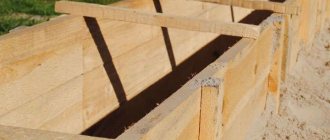
Small panel adjustable formwork - photo
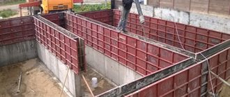
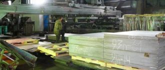
Focused on casting small concrete objects. It is distinguished by a small area of boards (no more than 3 sq.m.). The weight of the shields does not exceed 50 kg. This factor allows for their installation without the involvement of special lifting equipment. As a rule, collapsible small-panel formwork is used for indoor work. In particular, it is used to create interior partitions, small foundation elements, columns, etc.
This type of formwork is quite versatile. The use of special connecting elements and additional panels allows you to increase its dimensions without any problems. In addition, the inventory collapsible small-panel formwork allows professionals to assemble spatial blocks used for casting stepped structures.
Large panel formwork
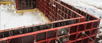
Large panel adjustable formwork - photo
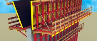
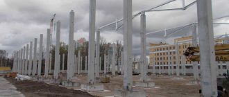
Used for concreting large-scale structures of great height and length. It is distinguished by a significant area of boards, the size of which can vary from 3 to 20 sq.m. Collapsible large-panel formwork is indispensable for the construction of high-rise buildings, workshops, hangars and other industrial facilities. All structural elements are designed to withstand the enormous pressure exerted by the concrete mixture and are characterized by increased reliability. The large area of the panels significantly reduces the assembly time of the structure and makes it possible to reduce the time required to construct the object.
Due to its significant weight, collapsible large-panel formwork requires the use of special equipment both at the installation and disassembly stages. Subject to the installation and maintenance rules, the formwork system can withstand over 500 work cycles!
Lifting and adjustable
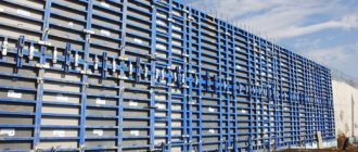
Climbing formwork - photo
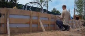
It has some similarities with large-panel systems. However, the way it is installed is completely different. Below we will look at this in more detail:
— Steel embedded parts are integrated into the concrete base on which the work will be carried out along the entire perimeter. They are used for installing anchors.
— The map is being assembled (a large-scale part of the formwork, up to 80 square meters in size). The card is used to fix the scaffolding with flooring and secure technological ladders.
— Next, using special lifting equipment, the card is moved to the concrete base and fixed to it using anchor bolts.
— The same algorithm is used to assemble other cards. After which they are fixed along the perimeter of the building from the outside.
— As soon as the external part is finished, the craftsmen move on to installing the internal circuit.
— The correct assembly of the formwork system is checked. The concrete mixture is poured evenly along the entire perimeter of the formwork.
— When the concrete reaches the required level of strength, the card is separated and the formwork is transferred to a new level using lifting equipment.
Climbing formwork is the optimal solution for the construction of multi-storey buildings. Due to the fact that it is moved to a new location in assembled form, it provides a significant reduction in construction time.
Block non-demountable systems
Volume-adjustable block-type formwork is supplied in the form of factory block forms or can be assembled into a single system of U- or L-shaped elements. Due to its non-dismountable design, the formwork is moved to the site in assembled form. Any operations with it are carried out using special lifting equipment. In commercial monolithic construction, block molds have gained well-deserved popularity in the manufacture of a variety of free-standing structures, from foundations to columns.
Block volumetric adjustable formwork allows you to cast concrete products of a clearly defined size and shape. In view of this, its use is advisable only in the manufacture of a large number of similar products.
Collapsible formwork
Formwork installation
§ 1. Types of formwork and process composition
Formwork along with auxiliary! devices serve to give instructions the design form, specified dimensions and position in space. The concrete mixture is placed in a deck and kept there until hardened. Thus, the formwork has a temporary purpose: it is removed as soon as the concrete reaches the required
(stripping) strength. Recently, they have begun to use formwork, which, after concreting the structure, remains in its body as a monolithically connected cladding.
The following types of formwork are distinguished: collapsible formwork (including block forms), mobile rolling formwork, horizontally sliding formwork, tunnel formwork, lifting formwork, climbing sliding formwork, adjustable volumetric formwork, lining formwork (non-removable) and pneumatic (Fig. VII.2).
The structures of the formwork, its supporting scaffolding or racks, fastening and other devices must be rigid, strong and stable, ensure ease of installation and disassembly, and also comply with the accuracy class and methods of reinforcement, laying and compaction of the concrete mixture adopted for the construction of this structure. The surface of the formwork directly adjacent to the concrete must be dense, have little adhesion to the concrete and have no cracks to prevent laitance from leaking out.
The most important indicator of the quality of formwork is its turnover,
i.e., reusable. The use of inventory multi-revolving formwork from standardized elements with modular changes in size and enlarged blocks helps to reduce the labor intensity and cost of formwork work, which still remains high. Formwork works account for 24-40% of labor costs for the construction of a reinforced concrete structure. Up to 3 million m3 of timber and about 150 thousand tons of steel per year are consumed for formwork.
For the manufacture of formwork, boards are used from wood of grades II, III and IV of coniferous species (the use of alder, aspen, beech is allowed), waterproof plywood, sheet and grade steel, fiberglass, hydrophobic particle boards and fibreboards, reinforced cement boards, asbestos cement sheets and pipes, steel woven metal mesh with 5x5 mm cells, airtight shells, inflatable cylinders, as well as concrete and reinforced concrete shell slabs.
Formwork panels can be made of one or more materials: wood, metal, reinforced concrete, wood-metal, fiberglass with a metal frame, etc. Supporting structures are made of round timber, stock steel, wood or wood-metal
Rice. VII.2. Types of formwork:
A
- collapsible;
b
- large shield;
c
- mobile rolling - sliding;
g
- lifting adjustable;
d
- lifting sliding;
e -
adjustable volumetric;
g
- formwork-cladding;
/ - formwork panels; 2
- clamps;
3 -
concreted part of the structure;
4
- supporting structures;
5
- ;
trolleys; 6
— rollers;
7 - fence; 8
— lift;
9 -
working flooring;
10
- suspended scaffolding;
// - house-crats; 12
— jacking rods;
13
— frame stand;
14 -
frame;
15
— articulated rods;
16
- opal-: ki-cladding slabs;
L
- reinforcement frame;
18
— anchoring loops .j
racks, frame supports and pipes. Devices for fastening, lifting or moving formwork are usually made of steel, in some cases - of wood or aluminum. Working floors and scaffolding are made of wood, inventory scaffolding is made of metal.
To reduce the adhesion of concrete to formwork, lubricants are used. The most common water-repellent lubricants are based on mineral oils or salts of fatty acids. Combined lubricants, for example ESO-GISI, are also effective. After 1-4 turns, the formwork is re-coated with lubricant. The process of applying lubricant is labor-intensive; it employs two workers.
Before construction begins, technological design is carried out: methods for concreting structures are prescribed, working drawings of formwork, supporting scaffolding, scaffolding, as well as devices for moving them are developed, instructions for the operation and disassembly of formwork are drawn up.
When designing reinforced concrete silos, industrial pipes, towers and other special structures, the construction process of which involves the use of inventory sliding or climbing formwork, it is necessary to take into account the peculiarities of the technology for producing such work and not recommend architectural and building structures that impede the use of formwork of these types.
Formwork, scaffolding and fastenings are designed for vertical and horizontal loads. In this case, the own weight of the formwork and scaffolding is determined from the drawings; the density of the freshly laid concrete mixture is taken to be 2500 kg/m3; weight of reinforcement - on average 10 kN per 1 m3 of reinforced concrete structure; loads from people and vehicles when calculating the deck and flooring - 25 MPa, the circle - 15 MPa and the scaffolding posts supporting the circle - 10 MPa; loads from vibration of the concrete mixture - 10 MPa.
To determine the lateral pressure P
from freshly laid concrete mixture, when calculating formwork structures of vertical surfaces, it is recommended to use the following data.
When compacting with deep vibrators,
if the height of the layer of the laid mixture
h
is less than or equal to the radius
R
of the vibrator, and the concreting speed v
is less than
P=ρh,
where p is the density of the concrete mixture. At v
;> 0.5 m/h, A>1 m
Р = р(0.27v+0.78)k1k2
-where kx
— coefficient depending on the mobility of the mixture:
kx
= 0.8 for concrete with cone settlement OK = 0...2 cm;
k1
= 1 for mixtures with OK = 4...6 cm;
ki
= 1.2 for mixtures with OK = 8... 12 cm;
k2
is a coefficient that takes into account the influence of the temperature of the concrete mixture:
k2
= 1.15—for mixtures with a temperature of 5...7°C;
k2 =
1 at 12…17°С;
k2
= = 0.85 at 28…32°С.
When compacting with external vibrators,
if
v
< 4.5 m/h and
h
=gC
2R,
P = ph;
at v
^ 4.5 m/h and
h >
2 m
R
= p (0.27v + 0.78)
k1k2.
The deflection of the formwork elements of open front surfaces should not exceed 1/400 of the span, closed surfaces - 1/250 of the span; the settlement of supporting elements and scaffolding should not be more than 1/100 of the span of the structure.
When calculating, the most unfavorable combination of loads is selected. All required regulatory data on loads, overload factors (from 1 to 1.5), and the resistance of the materials used during bending, tension, compression and crushing are given in SNiPs.
Steel formwork and accessories for it are manufactured at metal structures factories or in mechanical workshops of construction organizations. Plank and plywood formwork, scaffolding and fastening elements are made in the formwork shops of woodworking plants or in formwork workshops. Marked sets of formwork and auxiliary devices are delivered to the site under construction by truck or rail.
Installation of formwork begins with the organization of a working area, which is a space near the structure being erected, within which scaffolding, formwork elements, equipment and machines are located. At different zone levels, work stations are organized for the formwork teams, ensuring the required position of workers and safe work.
Light formwork is installed by specialized teams of formwork carpenters. Large-panel and large-panel, block forms and reinforced concrete shell slabs are installed by teams of formwork assemblers using cranes, winches, etc.
Collapsible formwork
Collapsible formwork is used in the construction of masses, foundations, columns, beams, purlins, frames, slabs, walls, bunkers, arches, etc. The technological process of constructing formwork is as follows. Formwork panels or large formwork elements assembled from them are installed manually or by crane and secured in the design position. After concreting and the concrete reaching strength,
allowing stripping, the formwork and supporting devices are removed following a certain sequence. After cleaning and, if necessary, repairing the formwork, it is moved to a new position.
The main types of collapsible formwork are small-panel, large-panel and block forms.
The small panel formwork (Fig. VII.3) is installed manually by two carpenters.
Rice. VII.3. Elements of collapsible small-panel formwork:
A
- plank board on stitched strips;
b
- a shield made of steel sheet with a frame of corners;
c —
a board made of waterproof plywood;
e -
steel clamp;
d
- wooden clamp;
/ - shield formwork; 2 —
stitching strip;
3
- steel sheet 2 mm thick;
4 - frame made of corners; 5 - frame made of wooden blocks; 6
— clamp branches; 7 - wedges
The mass of this formwork element is up to 70 kg. Formwork panels are made from edged or semi-edged boards with a thickness of 19...25 and a width of 150 mm on stitching strips (Fig. VII.3, a). The bottoms of the formwork of beams and purlins are made of boards 35...40 mm thick. It is recommended to join the edged boards into tongues or quarters, and protect the ends of the deck boards with steel corners. Formwork panels are also made from steel sheet, waterproof plywood with a thickness of 12 ... ... 16 mm and a length of up to 1500 mm (Fig. VI 1.3, b, c)
or fiberglass.
Clamps are made of strip steel or wooden blocks (Fig. VII.3, d, e).
Large panel formwork is installed and dismantled by crane. The mass of a formwork element—a large-size panel, solid or assembled from standardized panels (metal, wood, or combined)—■ reaches 500 kg.
An example of large-panel formwork is the unified combined formwork (UK.O) and unified steel formwork (USO) of the “Monolith” type developed by the Central Scientific Research Institute of Transport and Transport of the USSR State Construction Committee, designed for 100-300-fold turnover (Fig. VII.4, a).
Rice. VII.4. Monolith type formwork and block form:
I—
set of steel formwork type “Monolith”;
b - wood-metal panel of UKO formwork; e
- detail of the kim device;
d
- general view of the block form;
d
- layout of squeezing devices;
/ - steel-It sheet 2 mm thick; 2 -
frame made of corners;
3
- holes for supports;
4
- connecting corner;
5 - patches made of channels; 6
— gaskets;
7 - racks; 8 - traction; 9
— emphasis;
10 -
wedge;
// - cleaver; 12 —
mounted boards;
13 —
disk;
14
- spring;
15
- screw;
16
- nuts;
P
- formwork panels;
18 -
socket for release screws;
19
— struts;
20
- squeezing devices
Formwork panel U KO
(Fig. VII.4,
b)
consists of 23 mm planed boards assembled into tongue and groove. It is attached to a frame made of corners (63 X 40 X 4), which has stiffening ribs. The ends of the boards are protected with corners (20 X 20 X 3). The height of the panels is 300, 400, 500 and 600 mm, the length is 1200, 1300 and 2000 mm.
In USO formwork
the shield is made of sheet steel with a thickness of 3.5...4 mm (in the Yusson formwork - 3...4mm), framed
lined with corners. The formwork kit, in addition to the panels, contains fasteners, guide posts and others
elements (Fig. VII.4, a, b).
The KTI formwork developed by the USSR Ministry of Industry and Construction is also recommended.
Unified large-panel formwork designed by TsNIYOMTP is used for the construction of multi-story reinforced concrete buildings with a distance between walls from 2.4 to 7.2 m and a thickness of internal walls of 8...22 cm, external ones - from 14 to 22 cm, and single-layer ones - up to 50 cm.
Block forms are spatial structures that reproduce with their internal surfaces the shape of the concrete structure: foundation, column support, etc. (Fig. VI 1.4, d).
The formwork block is assembled from steel panels on detachable or hinged fasteners. Blocks
Rice. VII.5. Details of the scaffolding supporting the formwork:
A
— steel sliding stand;
b - sliding crossbars; c
- joints of log racks;
g
- sandbox;
d ■
—jack;
1
— basic tubular stand;
2
- nut;
3
— jack handle;
4
- chain;
5 - check; 6
— washer;
7 — retractable stand; 8 —
retractable beam;
9 — support stand; 10
— screw for securing the stand;
// - farm; 12
— retractable beam;
13
- wire;
14
- pack steel;
15
- wooden piston;
16
- sand;
P
- hole with plug;
18
— jack screw
Rice.
VII.6. Schemes for installing foundation formwork: a -
installation of strip foundation formwork;
b - installation of block steel formwork for a stepped foundation; c
- the same, column;
/ - first stage formwork; 2 - fittings; 3
- concreted first step;
4
- second stage formwork;
b
- screed;
€
- brace;
7 - foundation reinforcement block; 8
- foundation formwork block;
9
— pneumatic wheel crane;
10
— column formwork block
large masses are mounted and dismantled by crane.
The scaffolding supporting the formwork can be floor-to-floor, rack-mounted or suspended.
Floor-by-floor
scaffolding consists of inventory wooden or steel telescopic racks (Fig. VII.5, c) resting on the ground or underlying floor.
Such scaffolding is used in the construction of multi-tiered buildings to support the formwork of ribbed and flat floors at a height of up to 6 m. The scaffolding set includes sliding crossbars (Fig. VI 1.5, b)
that allow spans from 1.5 to 4 and from 4 to 6 m to be covered .
Rack-mounted
scaffolding is erected on site to the required height from logs 12...14 cm thick (Fig. VII.5,
c).
'! For smooth turning, i.e. lowering the supports supporting the formwork of vaults, arches and beams of large spans, special devices are used: jacks, sandboxes, etc. (Fig. VII.5,
d, e).
Hanging
scaffolding is used for concreting beams and purlins for significant
no height with rigid reinforcement, to which the scaffolding is attached.
When installing collapsible formwork on the ground, the site is cleared of debris and unevenness is eliminated. The floors are cleared of construction debris before installing formwork on them. In order to correctly install the formwork, the main and auxiliary alignment axes, benchmarks and other auxiliary signs indicating vertical marks are determined and secured.
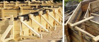
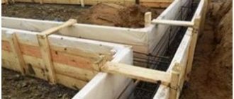
Formwork for strip foundations
assembled from panels to the height of the foundation or first install the panels of the lower stage, after concreting which the formwork of the upper stage is installed (Fig. VII.6,
a).
Formwork for small stepped foundations
under the columns are made of wooden panels. First, cover panels are installed parallel to each other on the edge, and embedded panels are inserted between them. Using spacers, the embedded panels are pressed against the stop strips on the covering panels, then the wire ties are installed and tensioned. In this position the box is secured in place. The formwork of the glass for the prefabricated column is fastened with nails to the upper box, guided by the axes marked on it and on the glass
Rice. VI 1.7. Formwork of massifs and foundations for equipment:
A
— large-sized wooden panel;
b - panel rearrangement diagram; c -
installation diagram of the steel formwork of the foundation for technological equipment;
d
- arrangement of reinforced concrete racks of the formwork frame;
; - contractions; 2
— formwork panel;
3
- coupling bolts;
4
— slings;
5 — mounting loops; 6 —■
wooden wedges;
7 - diagonal connection; 8
— spacer;
9
- cord;
10
- stretch marks;
11
— reinforced concrete racks;
12
— formwork blocks;
13
— reinforced concrete beams;
14
— suspended staircase;
15
- vertical
communications
.
Formwork for large stepped foundations
in the form of a steel block mold, it is installed with a crane (Fig. VII.6,
b, c)
on the concrete preparation. A nest-former or sub-column formwork is mounted under the prefabricated columns on the upper ledge.
Large-panel wooden panels
array formwork is installed by edges
nom and secured in the desired position with cords or struts. It is preferable to erect high massifs in two-tier formwork (Fig. VII.7, a, b),
eliminating breaks for curing concrete in single-tier panels.
Formwork of foundations for equipment
has complex contours and variable height due to the presence of tunnels and conductor devices for anchor bolts in the foundations.
The installation of formwork is alternated with reinforcement and installation work. To fasten the panels, prefabricated reinforced concrete racks and crossbars remain in the body of the concrete. Works
are done in the following sequence: using a crane, prefabricated reinforced concrete shoes are installed inside the future foundation, into which racks are installed, and crossbars on them. On the racks (Fig. VII. 7, c, d)
and crossbars hang panels assembled from metal and wooden panels. All formwork, conductors and other devices are installed, if possible, immediately on the entire foundation in order to perform an accurate geodetic check before concreting.
Column formwork
assembled from planks, plywood or steel universal panels. When reinforcing with load-bearing reinforcement blocks, a column reinforcement block is installed with a crane into the design position, which is welded with the outlets of the reinforcement of the column (foundation) or the connecting parts of the column reinforcement of the underlying floor. Then formwork panels or panels assembled from them for the entire height of the column are placed on the reinforcement block and secured to each other with spring-rod brackets or in another way.
If the column is reinforced with separate rods, assembling a reinforcement frame from them, then first a formwork box made of three panels is installed by hand turning. Work begins with attaching frames that determine the exact (axial) position of the formwork boxes. The frames are sewn to plugs placed in the fresh concrete of the floor slab. The axes of the frames must coincide with the axes painted on the concrete, and the surface of the quarter, into which the formwork box will then be installed, must coincide with the marks marked on the outlets of the reinforcement (Fig. VII.8, a, b).
The box is sewn to the frame with nails and verticality is ensured by inclined spacers. The closing (fourth) panel of the box is attached when the reinforcement frame of the column is already connected and the formwork of the beams is installed. The clamps are placed according to the markings on the panels. The verticality of the formwork is verified with a frame plumb line.
Ribbed slab formwork
consists of formwork of slabs, beams and purlins, as well as sliding telescopic racks supporting them (see Fig. VII.5,
a).
The bottom of the box is installed on the heads of the racks (Fig. VI 1.8, c, d), and
then the side panels of the beams, which are attached with clamping strips to the heads of the racks, and at the top - to the formwork of the slabs. The latter consists of flooring panels laid on edges on circles of boards. The slab formwork circles rest on subcircular boards nailed to the stitching strips of the side panels of the beams. The distance between circles is calculated and is usually 500... .. 1000 mm.
The racks for the purlins are installed on the logs (Fig. VII.8, e),
which contributes to the distribution and transfer of pressure to the racks of the underlying floor. When the height of the racks is more than 3 m, their stability is ensured by horizontal braces and braces.
Formwork of beams, purlins and crossbars
made from wooden (Fig. VII.8,
d, e)
or steel panels (Fig. VII.8,
i).
It is advisable to arrange boxes of a combined design, in which the bottoms are made of planks and the side panels are steel, since the turnover of the side panels is greater than that of the bottom panels. Suspended formwork is attached to rigid reinforcement (channels, I-beams, etc.).
formwork ,
having a large height, they are installed in stages: they set up scaffolding and arrange a working floor, lay the bottom of the box along the marks and attach side panels to it on one side, and after installing the reinforcement, install the side panels of the formwork on the other side.
Formwork of walls and partitions
They are sets of plank or steel (Fig. VI 1.8,
g)
panels, guide posts, purlins and tie bolts.
First, formwork panels are installed on one side of the wall, for example, on the side of the pit slope. Having installed the reinforcement, install the second wall of the formwork, secure the tie bolts, and then during the concreting process, wooden spacers are placed next to the tie bolts, which determine the design thickness of the wall. Walls with a thickness of more than 250 mm are formworked to a height of up to 6 m. If the wall thickness is less, the panels of the second side,
Formworks are installed in tiers to a height of no more than 1.5 m.
In dry, hot weather, the installed plank formwork should be systematically watered with water to protect it from warping during drying and the appearance of cracks in the panels and joints.
Rice. VII.8. Formwork of columns, ribbed slabs, purlins and walls:
a ■
— frame for column formwork;
b - column formwork box; c
- formwork of beams and ribbed floor slabs;
g
- the same, girders and beams;
d
- cross-section of the purlin formwork in the absence of a slab;
e - floor racks; g
- wall formwork made of standardized steel panels with fastening with spring-rod brackets;
and
- metal formwork of columns and girders on sliding racks;
1
- plugs embedded in concrete;
2
- frame;
3
— column box;
4
- clamps;
5 — head of the rack; 6
— pressure boards;
7 - under-circular boards; 8
- circled;
9
— frieze boards;
10
— side shields;
// - bottom of the box; 12
— slab formwork panels;
13
- screed;
14
—■ contraction;
15
— racks;
16
- concreted floor;
17
— logs for racks;
/8—splits; 19
- concrete floor;
20
- stand;
21
— steel shield;
22
— spring-rod bracket;
23
- purlin formwork;
24
- clamp;
25
— sliding rack
Mobile rolling formwork
Formwork in the form of inventory wooden blocks or metal sections,
rolled on rails, used for the construction of linear structures: passage tunnels, collectors, slurry pipelines, settling tanks, tunnels
large cross-section, etc. Such structures are concreted separately: first the bottom, on which the paths for moving the formwork are mounted, then in the rolling formwork - the walls and coverings. For small tunnels or collectors, wooden block formwork is used in the form of a system of interconnected circles, covered with boards 30 mm thick.
Inventory wood-metal roll formwork
(Fig. VI 1.9) are used for open-pit construction of tunnels with a cross section from 1300 x X 1300 to 2300 x 2820 mm.
The 3200 mm long internal formwork section consists of four steel frames covered with boards, waterproof plywood or steel sheets. The middle pillars of the frames are equipped with jacks, and the crossbars are pivotally connected to the pillars. The lower crossbars are sliding; they rest on rollers that move on portable rails.
The external formwork section consists of U-shaped wooden frames with formwork panels attached to them. When stripping, using jacks located on the frame posts, move the formwork panels away from the walls by 3-4 cm.
To remove the internal formwork, the uprights of the steel frames are compressed by screwing in jacks, and the entire hinged structure is torn off from the concrete. After this, the beams of the lower crossbar are pushed in to create a gap between the bottom of the panels and the finished walls. The formwork sections are moved by a winch. In transport position there is a danger
the splint is shown on the left side of the figure. VII.9.
For large tunnels, rolling formwork is made in the form of metal sections.
The steel shell of the formwork, which has hinges, is attached with jacks to a trolley that moves along rails. The shell is installed in the design position with jacks and secured in place with spacers and wedges. Then the jacks are removed and the cart is moved to another grip.
When it is necessary to remove the concrete section, the trolley is brought under the shell. By screwing the jacks, the shell is lowered onto the trolley, which rotates on hinges, after which the section is moved forward under the installed formwork of the next sections, which makes it possible to work on several grips.
In Fig. VIII.2, in
horizontally sliding rolling formwork for
is shown In the horizontal direction, the formwork moves along rail tracks using electric motors mounted on a trolley.
How is a typical climbing formwork constructed?
Structurally, such formwork is quite complex. It includes an inner and outer shell. The inner part is treated with a special release agent and is in direct contact with the concrete solution. Concrete is poured into the mold using special working platforms. To achieve the highest quality of construction and high structural strength, concreting is performed in layers. The height of the tier often does not exceed 2-2.5 m.
The main element of the outer shell of the formwork system is rectangular or trapezoidal steel panels. They are secured to each other using high-strength locks. The assembled structure must be checked for compliance with the design dimensions. Please note that when installing the upper tier, you should ensure that it overlaps the concreted part of the structure by at least 10 cm.
As mentioned above, any climbing formwork has an internal part. To assemble it, smaller panels are used than the outer shell panels. Moreover, they are installed in 2 tiers. The required gap between the outer and outer parts is achieved using special spacer-clamps.
Types of adjustable formwork
According to their design, volumetric adjustable formwork is divided into four main types:
- Small shield. The maximum dimensions of a shield of this design are 1200 mm in width and 1500 mm in height. This type of formwork system is suitable for installation and dismantling without the use of lifting equipment.
- Large panel adjustable formwork. The width of each module reaches 2400 mm, maximum height up to 3000 mm.
- Liftable and adjustable. A special feature of this type is the fastening of the outer contour from the outside of the building using special anchors and mortgages.
- Block-type adjustable formwork. This type of formwork is made in the form of ready-made block forms.
Key advantages and disadvantages of adjustable formwork for walls and other structures
The main advantage of such systems is the ability to quickly erect multi-storey buildings of complex shape. At the same time, builders have the opportunity to cast entire floors with load-bearing walls, interior partitions, elevator shafts and columns. The design thought out to the smallest detail and the use of high-quality materials provide a long service life of adjustable formwork systems. The possibility of repeated use can significantly reduce construction costs in the long term.
The disadvantages of adjustable formwork include the complexity of installation and significant dimensions that require the use of special equipment.
REMOVABLE FORMWORK
In the process of constructing large-scale structures made of monolithic concrete, adjustable formwork has gained particular popularity. Its design makes it possible to quickly dismantle and install the formwork system at a new location. Using adjustable formwork, you can cast a wide range of different structures in a short time. As a rule, these are foundations, load-bearing walls and partitions, interfloor ceilings, columns, etc. Below we focus on this in more detail.
Rent of adjustable formwork is a balanced solution for reducing construction costs!
It is no secret that the cost of formwork systems for multi-storey monolithic construction is very high. Their acquisition is economically feasible only if they are used repeatedly. offers you to rent any type of adjustable formwork on favorable terms. The systems we present are in impeccable technical condition and allow us to produce concrete products of excellent quality. We will take on all the hassle of selecting the type of formwork, its transportation, installation, dismantling, maintenance and storage!
Climbing formwork
This is another type of adjustable formwork, much like large panel formwork. However, there are significant differences in the installation method:
- Initially, mortgages are installed in the concrete base along the entire perimeter from the outside for installing fastening anchors.
- Then a large element of the formwork system (card) with an area of up to 80 m² is assembled on a horizontal surface. Scaffolding for arranging the flooring and technological ladders are attached to the map.
- Using a crane, the assembled card is brought to the concrete base wall and secured to it using anchors.
- The remaining cards are collected in the same way and mounted on the outside along the entire perimeter of the structure.
- Then they begin to install the internal contour of the formwork system.
- Pouring the concrete mixture can be carried out simultaneously throughout the entire floor of the building being constructed.
- After the concrete has hardened, the cards are separated from each other, the mounting anchors are unscrewed and moved to the next level using a crane.
Having collected cards for the construction of the walls of the first floor, they are simply rearranged in assembled form from level to level. This formwork is ideal for the construction of multi-storey buildings for various purposes and provides high speed concrete laying.
The most famous manufacturer: “FORA” (Russia).
Device
Climbing formwork consists of internal and external panels, fasteners, lifting devices, supporting devices and flooring for workers. The concrete is poured directly into the mold from the inner panels, while the outer ones are needed for support. This design provides the formwork with the ability to withstand the deforming effects of the concrete mixture. Working platforms are installed along the perimeter of the formwork, allowing you to control the pouring process at height.
The equipment is designed in such a way that it can be moved vertically without dismantling the system. As the concrete mixture hardens, the mold moves higher to pour the next portion. The size of one tier is usually 2-2.5 meters.
What does climbing formwork consist of?
Like any other formwork structure, climbing formwork is assembled directly at the construction site and consists of the following main elements:
- internal and external formwork panels;
- suspended scaffolds used for concreting;
- work site;
- lower scaffolding.
The design also includes a mechanism that allows you to move the formwork panels in the radial direction and a mine lift. In this case, additional (auxiliary) elements of formwork systems are suspension rollers, ties, bolts, brackets and overlays, which are used to securely fix the structure to a monolithic structure.
The working platform of the climbing formwork is a rigid diaphragm that is attached to the lifting head. It is installed at the lowest point, after which it can be lifted up the shaft hoist. There is an annular hole in the flooring, which is necessary for the release of reinforcement and successful placement of the concrete mixture into the formwork system. As the formwork is raised, the circumference of the working platform decreases. This occurs due to the use of excess panels and shields.