Insolation of premises is the irradiation of the internal and external surfaces of architectural objects (residential and non-residential buildings) with sunlight (solar radiation). The intensity of solar radiation fluxes on the surface in architecture is adjusted by selecting glazed elements of enclosing structures and appropriate positioning of the house to the cardinal points and taking into account climatic features.
This review examines in detail all available recommendations, standards and techniques for insolation of premises in residential buildings.
Insolation of house premises taking into account the trajectory of the sun
The sun brings not only light to the house, but also warmth. And when solving the issue of insolation, it is necessary to carefully compare these effects. As a simple example, additional heat that is appropriate in winter in some rooms can cause discomfort in the summer months. Therefore, when placing windows and light openings, the issue of increasing (decreasing) the amount of solar heat is no less important than the task of increasing the flow of daylight.
Let's consider the rules for placing the house on the site so that insolation can be easily controlled:
| By placing the building at an angle (diagonal) to the southern side of the horizon, you can receive the maximum possible amount of sunlight. During the day, direct rays of the sun penetrate into each room at certain hours, and the rooms located at the southern end of the building are illuminated by the sun from morning to evening. |
| Shading windows is an effective method of insolation during the heat of the day. As the sun moves from east to west, the heat of the day increases, and with it the need to shade south- and west-facing rooms increases. To ensure the penetration of the warmth of the winter sun into the home, but to prevent overheating of the home in the summer, trellises with climbing plants that lose their leaves in winter, as well as sun blinds (shutters, awnings, umbrellas) or tall trees located on the south (west) side of buildings will help with falling leaves in winter. |
| The deep overhang of the roof provides shade in summer and good penetration of sunlight into the house in winter. This is due to the fact that in the summer months the sun is higher in the sky than in winter. |
We have already mentioned the balance of light and heat during insolation of premises. Expanding this issue further, it can be noted that in most climatic zones the morning is cool. And if you locate the bedroom in the eastern zone, you don’t have to worry about overheating. Only minimal sun protection is required here. If you have to get up early, direct light coming from the east will bring warmth and help you cope with your morning activities with more pleasure.
The next important point of insolation is relevant for regions located in the northern hemisphere. In these climatic conditions, the northern side of the buildings is almost not heated by the sun, and therefore there is no opportunity for maximum use of solar heat. Most of the heat escapes through windows facing the north side of the building. Therefore, depending on the project, it is better to abandon windows in this area or use them with great care (fewer numbers, small sizes, high-quality components and reliable connections).
Quality indicators of lighting.
Qualitative indicators of lighting are associated with the phenomenon of reflection of light flux from various surfaces.
Reflection is the return of radiation by an object without changing the wavelengths of its constituent monochromatic radiation.
Qualitative indicators include the glare index and the luminous flux pulsation coefficient and a generalized discomfort index.
Glare index P is a criterion for assessing the glare of a lighting installation.
Р= 103( s -1),
where s is the glare coefficient, equal to the ratio of the threshold brightness differences in the presence and absence of blinding sources in the field of view.
The presence of bright sources in the field of view reduces the level of almost all visual functions, and, therefore, overall performance.
To reduce the influence of a brilliant source, various types of shielding grilles are used, creating a protective angle for the observer, and the height of the suspension of lamps above the level of the working surface varies.
The glare effect of lighting installations depends on the light distribution of the lamps falling into the field of view, their power, brightness, the amount of illumination they create and the reflectance of the working surface to which the observer's eye is adapted.
Adaptation of the eye to changed lighting conditions is called adaptation . There are dark and light adaptations.
Dark adaptation is the adaptation of the eye to work in conditions of high brightness of the visual field during the transition from day vision to night vision (5-6 minutes).
Light adaptation – from darkness to light (1.5-2 minutes).
During the period of time during which adaptation occurs, a person has difficulty distinguishing objects, which can cause an accident.
When the light flux pulsates, a stroboscopic effect occurs, as a result of which rotating objects may appear motionless or have a different direction of rotation, which can also lead to injury.
Illumination pulsation coefficient Kp is a criterion for assessing the relative depth of illumination fluctuations as a result of changes in the flow of gas-discharge lamps powered by alternating current.
Kp=(E max - Emin)/2Esr*100%,
where Еmax, Emin, Еср - maximum, minimum and average illumination value for the period of alternating current oscillations (0.02 s), lux.
There are standard values for Kp: the upper permissible limit Kp = 20%, the lower permissible limit is 10%.
Another phenomenon is the phenomenon of discomfort , classified as a feeling of discomfort or tension that occurs when the distribution of brightness in an illuminated space is unsatisfactory. In this case, there may not be a decrease in visual functions, only a violation of the conditions of visual comfort occurs, which leads to distraction, decreased concentration, as well as visual and general fatigue.
In our country, the quantitative criterion that defines this phenomenon is the combined discomfort indicator UGR , a criterion for assessing uncomfortable brightness that causes unpleasant sensations when the brightness is unevenly distributed in the field of view:
,
where: — brightness of the brilliant source, cd/m2;
— angular size of the brilliant source, erased;
— index of the position of the bright source relative to the line of sight;
— adaptation brightness, cd/m2.
Lighting calculations.
The initial data for lighting calculations are: the standardized value of the minimum or average illumination; type of light source and lamp, height of the lamp suspension above the work surface; geometric dimensions of the illuminated room or open space; reflection coefficients of the ceiling, walls and calculated surface of the room.
The illumination of any point has two components: direct, created directly by the lamps, and reflected, which is formed by the light flux reflected from the ceiling and walls.
Luminous flux utilization factor method. Allows you to calculate the lighting installation taking into account the direct and reflected components of illumination. The luminous flux utilization coefficient Uoy is understood as the ratio of the luminous flux incident on the illuminated surface to the total luminous flux of all luminaire lamps. The utilization factor Uoy depends on the type of light distribution of the luminaire, the height of the luminaire suspension above the illuminated surface, the geometric characteristics of the illuminated room, as well as the reflectance of the ceiling, walls and working surface of the room.
The dependence of Uov on geometric characteristics is determined by the room index:
in= ab/(h(a+b)),
where a is length, m; b
— width, m;
h
- height from the lamp to the working surface, m.
As the room index value increases, the utilization factor increases, since this increases the proportion of the luminous flux directly incident on the illuminated surface. The utilization factor also increases with increasing reflection coefficients of the ceiling of the walls and the working surface.
Number of lamps N
, necessary to create a given level of illumination E in the illuminated room, is determined by the expression;
N =EszKз/(nФUoy)
where s is the area of the room, m2; z is the ratio of average illumination to the minimum, characterizes the unevenness of illumination and is 1.15 for incandescent lamps and DRL, DRI lamps and 1.1 for fluorescent lamps; K3 is a safety factor that takes into account the decrease in lamp luminous flux over time; is taken equal to 1.2 for incandescent lamps and 1.4 for gas-discharge lamps; n is the number of lamps in the lamp, pcs.; F
— luminous flux of one lamp in a lamp, lm; Uoy is the coefficient of luminous flux utilization.
Calculation of lighting using the luminous flux utilization factor method.
When designing a lighting installation, it is necessary to resolve the following basic issues:
· select the lighting system and type of light source,
· set the type of lamps,
· place lamps,
· specify the number of lamps.
It should be taken into account that the illumination of any point inside the room has two components: direct, created directly by the lamps, and reflected, which is formed by the light flux reflected from the ceiling and walls.
The initial data for lighting calculations are:
· normalized value of minimum or average illumination,
· type of light source and lamp,
· installation height of the lamp above the working surface,
· geometric dimensions of the illuminated room or open space,
· reflection coefficients of the ceiling, walls and calculated surface of the room.
The illuminated volume of the room is limited by enclosing surfaces that reflect a significant part of the light flux incident on them from light sources. In indoor lighting installations, reflective surfaces include the floor, walls, ceiling and equipment installed in the room. In cases where the surfaces enclosing the space have high reflectance values, the reflected component of illumination can also be of great importance and its consideration is necessary, since reflected fluxes can be comparable to direct fluxes and their underestimation can lead to significant errors in calculations.
The method under consideration makes it possible to calculate a lighting installation (OU) taking into account the direct and reflected components of illumination and is used to calculate the overall uniform illumination of horizontal surfaces equal in size to the floor with lamps of any type.
The utilization factor of a luminous flux as the ratio of the luminous flux incident on the design plane to the luminous flux of light sources
(1)
where Ф
p – luminous flux incident on the design plane;
F
l – luminous flux of the light source; n – number of light sources (lamps).
The OS utilization coefficient, which characterizes the efficiency of using the luminous flux of light sources, is determined, on the one hand, by the light distribution and placement of lamps, and on the other hand, by the ratio of the dimensions of the illuminated room and the reflective properties of its surfaces.
The required flux of light sources (lamps) in each lamp F, to create normalized illumination, is found by the formula:
(2)
where E
– specified minimum illumination, lux;
Кз – safety factor; S – illuminated area (calculated surface area), m2; z – ratio E
av/
E
min;
N
– number of lamps;
U
оу – utilization factor in fractions of a unit.
According to the calculated value of luminous flux Fl
and the network voltage, the nearest standard lamp is selected, the flux of which should not differ from
Fl
by more than –10% ¸ +20%. If it is impossible to choose with such an approximation, N is adjusted.
With the selected type of luminaire and spectral type of lamps, the flux of lamps in each lamp is F
1 can have different meanings.
The number of lamps in a row N
is determined as
(3)
where Ф
1 – flow of lamps in each luminaire.
The total length N of luminaires is compared with the length of the room, and the following cases are possible:
· the total length of the luminaires exceeds the length of the room
: it is necessary either to use more powerful lamps (which have more flux per unit length), or to increase the number of rows;
· the total length of the lamps is equal to the length of the room
: the problem is solved by installing a continuous row of lamps;
· the total length of the lamps is less than the length of the room
: a row is accepted with gaps l between the lamps evenly distributed along it. It is recommended that l does not exceed approximately 0.5 of the design height (except for the case of using multi-lamp luminaires in public and administrative buildings).
z included in (2)
, which characterizes the unevenness of lighting, is a function of many variables and depends to the greatest extent on the ratio of the distance between the lamps to the design height (
L / h
), with an increase in which
z
increases sharply.
With L / h
not exceeding the recommended values,
z
equal to 1.15 for incandescent lamps and DRLs and 1.1 for fluorescent lamps when the lamps are arranged in the form of luminous lines.
For reflected lighting we can assume z
= 1.0.
To determine the utilization factor U
ou the index of room
i
using the formula:
(4)
where A
– length of the room,
B
– its width,
h
– estimated height.
For rooms of practically unlimited length we can consider i
=
B/h
.
To simplify the definition of i
There are special reference tables (Table 1).
In all cases i
rounded to the nearest table values;
for i
> 5
i
= 5 is accepted.
As the room index value increases, the utilization rate of the luminous flux increases, since this increases the proportion of the luminous flux directly incident on the illuminated surface. The utilization factor also increases with increasing reflection coefficients of the ceiling, walls, and design surface.
When calculating op-amps with standard luminaires U
oh is determined from reference tables taking into account the reflection coefficients of walls, ceiling, floor and room index. The values of utilization factors for luminaires with typical luminous intensity curves (LIC) are given in table. 2.
The procedure for calculating the op-amp using the luminous flux utilization factor method is as follows:
· the height of the suspension of lamps above the working surface h
p, type and number of lamps in the room (Table 4);
· set the safety factor K
z and correction factor
z
;
· for visual work characteristic of a given room, according to table. 3 the normalized value of illumination in the design plane E
;
· for a given (with certain geometric dimensions) room according to the table. 1 determine the index of room i
;
· according to reference tables, for example according to table. 2, depending on the type of lamp, the reflection coefficients of the ceiling, walls, and calculated surface, the utilization factor U
OU;
· using formula (2) calculate the luminous flux Ф
in the lamp, necessary to create illumination
E
not lower than that standardized for the entire period of operation of the lighting installation;
· according to the calculated value of luminous flux F
and network voltage from table.
5, the nearest standard lamp is selected, the flux of which should not differ from F
by more than –10 – +20%.
If it is impossible to choose with such an approximation, N
.
Sometimes the inverse problem is solved - using the known luminous flux F
, the required number of lamps or luminaires
N
to obtain the normalized illumination
E.
Table 1
Room index i
at A/B £ 3
| Room area S, m2 | Meaning i p at design height | ||||||
| 2,0 | 2.2 | 2,5 | 2,7 | 3,0 | 3,5 | 4,0 | |
| 20 | 1,1 | 1,0 | 0,9 | 0,8 | 0,7 | 0,6 | 0,5 |
| 40 | 1,5 | 1,5 | 1,25 | 1,1 | 1,0 | 0,9 | 0,8 |
| 60 | 1,75 | 1,75 | 1,5 | 1,5 | 1,25 | 1,1 | 1,0 |
| 80 | 2,25 | 2,0 | 1,75 | 1,5 | 1,5 | 1,25 | 1,1 |
| 100 | 2,5 | 2,25 | 2,0 | 1,75 | 1,5 | 1,5 | 1,25 |
| 200 | 3,5 | 3,0 | 2,5 | 2,5 | 2,25 | 2,0 | 1,75 |
| 300 | 4,0 | 4,0 | 3,5 | 3,0 | 2,5 | 2,25 | 2,0 |
| 500 | — | 5,0 | 4,0 | 4,0 | 3,5 | 3,0 | 2,5 |
table 2
Utilization factor ( U
ou) lamps with a typical luminous intensity curve KSS
| Type KSS | Meaning U OU, % | |||||||||||||||||||||||
| at rп=0.7; rc=0.5; rr=0.3 and i equal | at rп=0.7; rc=0.5; rр=0.1 and i equal | at rп=0.7; rc=0.3; rр=0.1 and i equal | at rп=0.5; rc=0.5; rr=0.3 and i equal | |||||||||||||||||||||
| 0,6 | 0,8 | 1,25 | 2 | 3 | 5 | 0,6 | 0,8 | 1,25 | 2 | 3 | 5 | 0,6 | 0,8 | 1,25 | 2 | 3 | 5 | 0,6 | 0,8 | 1,25 | 2 | 3 | 5 | |
| D –1 | 36 | 50 | 58 | 72 | 81 | 90 | 36 | 47 | 56 | 63 | 73 | 79 | 28 | 40 | 49 | 59 | 68 | 74 | 36 | 48 | 57 | 66 | 76 | 85 |
| D 2 | 44 | 52 | 68 | 84 | 93 | 103 | 42 | 51 | 64 | 75 | 84 | 92 | 33 | 43 | 56 | 74 | 80 | 76 | 42 | 51 | 65 | 71 | 90 | 85 |
| L | 32 | 49 | 59 | 71 | 83 | 91 | 31 | 46 | 55 | 65 | 74 | 83 | 24 | 40 | 50 | 62 | 71 | 77 | 32 | 47 | 57 | 69 | 79 | 90 |
Table 3
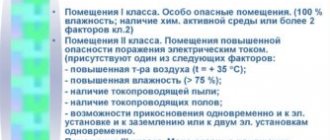
SanPiN 2.2.4.3359-16. “Sanitary and epidemiological requirements for physical factors in the workplace”
| Characteristics of visual work | Least or equivalent. size of discrimination object, mm | Visual work category | Visual work subcategory | Contrast of subject with background | Background characteristics | Artificial lighting | ||||
| Illumination, lux | Combination of normalized values of the combined URG discomfort index and pulsation coefficient | |||||||||
| with a combined lighting system | with general lighting system | |||||||||
| Total | including from the total | URG | Kp, % | |||||||
| Highest precision | Less than 0.15 | I | A | Small | Dark | 5000 4500 | 500 500 | — — | 22 19 | 10 10 |
| b | Small Medium | Medium Dark | 4000 3500 | 400 400 | 1250 1000 | 22 19 | 10 10 | |||
| V | Small Medium Large | Light Medium Dark | 2500 2000 | 300 200 | 750 600 | 22 19 | 10 10 | |||
| G | Medium Large Large | Light Light Medium | 1500 1250 | 200 200 | 400 300 | 22 19 | 10 10 | |||
| Very high precision | From 0.15 to 0.30 | II | A | Small | Dark | 4000 3500 | 400 400 | — — | 22 19 | 10 10 |
| b | Small Medium | Medium Dark | 3000 2500 | 300 300 | 750 600 | 22 19 | 10 10 | |||
| V | Small Medium Large | Light Medium Dark | 2000 1500 | 200 200 | 500 400 | 22 19 | 10 10 | |||
| G | Medium Large Large | Light Light Medium | 1000 750 | 200 200 | 300 200 | 22 19 | 10 10 | |||
| High precision | From 0.30 up to 0.50 | III | A | Small | Dark | 2000 1500 | 200 200 | 500 400 | 25 22 | 15 15 |
| b | Small Medium | Medium Dark | 1000 750 | 200 200 | 300 200 | 25 22 | 15 15 | |||
| V | Small Medium Large | Light Medium Dark | 750 600 | 200 200 | 300 200 | 25 22 | 15 15 | |||
| G | Medium Large Large | Light Light Medium | 400 | 200 | 200 | 25 | 15 | |||
| Medium accuracy | From 0.50 up to 1.0 | IV | A | Small | Dark | 750 | 200 | 300 | 25 | 20 |
| b | Small Medium | Medium Dark | 500 | 200 | 200 | 25 | 20 | |||
| V | Small Medium Large | Light Medium Dark | 400 | 200 | 200 | 25 | 20 | |||
| G | Medium Large Large | Light Light Medium | — | — | 200 | 25 | 20 |
| Low accuracy | From 1.0 up to 5.0 | V | A | Small | Dark | 400 | 200 | 300 | 25 | 20 |
| b | Small Medium | Medium Dark | — | — | 200 | 25 | 20 | |||
| V | Small Medium Large | Light Medium Dark | — | — | 200 | 25 | 20 | |||
| G | Medium Large Large | Light Light Medium | — | — | 200 | 25 | 20 | |||
| Rough (very low precision) | More than 5 | VI | Regardless of the characteristics of the background and the contrast of the object with the background | — | — | 200 | 25 | 20 | ||
| Working with luminous materials and products in hot shops | More than 0.5 | VII | Regardless of the characteristics of the background and the contrast of the object with the background | — | — | 200 | 25 | 20 | ||
| General monitoring of the production process: constantly | VIII | A | Regardless of the characteristics of the background and the contrast of the object with the background | — | — | 200 | 28 | 20 | ||
Table 4
Insulation of premises when designing windows taking into account the climate of the region
To determine the optimal size and placement of windows, it is largely necessary to be guided by the climate of the region. Let us highlight the basic rules of insolation, taking into account the climate and purpose of the room:
| In regions that suffer from a lack of sunlight, placing windows high in the wall allows deep, bright light to enter the room. |
| In hot climates, it is recommended to position or shade windows so that they only allow indirect light from the north side (or dim early morning light). |
| The beveled frames of the window frames (dawn angle) let in a large amount of light without blocking the light rays around the perimeter of the window. |
| Windows (or light openings), one of the corners of which is directly adjacent to the adjacent wall, allow light to stream across the surface, creating a pleasant glow without sharp contrasts between light and twilight. |
The previous paragraph already discussed the features of glazing northern walls in cold regions. In these conditions, it is very important to stay warm. This is done by minimizing heat loss from glazing. Windows, if they are included in the project in the northern zone, are usually made small and placed in thick walls with powerful, reliable thermal insulation. With such restrictions on the opening area, windows should be placed so that they are guaranteed to provide a sufficient amount of light in each room.
In regions with warm climates, there are no strict restrictions on window sizes. The windows here can be made large. But at the same time, it is necessary to provide additional possibilities for limiting the light flux using landscapes, umbrellas (curtains) and louvres on the openings.
1.1. Quantitative indicators
Quantitative indicators include: luminous flux, luminous intensity, illumination, brightness, reflectance.
Luminous flux (F) – the power of the luminous flux of radiation, estimated by visual sensation by the human eye. The dimension of the luminous flux is lumen (lm).
Luminous intensity (J) is the spatial density of the luminous flux in a given direction, i.e. luminous flux related to the solid angle ω at which it is emitted
, candela (cd), where
ω is the solid angle in steradians (sr).
Illumination (E) - the density of the luminous flux on the surface it illuminates - the luminous flux related to the area of the illuminated surface S, measured in m2, provided that it is evenly distributed over the surface when the light from the source falls on it perpendicularly
Brightness (B) is the luminous quantity directly perceived by the eye. It is determined by the ratio of the light intensity in a given direction to the area of projection of the emitting surface onto a plane perpendicular to the direction of radiation
The values of the maximum brightness values on the working surface are given in [4], table 1, page 14.
The reflectance of a surface r characterizes its ability to reflect the light flux incident on it. It is determined by the ratio of the reflected light flux to the incident one
The values of the coefficient (r) for surfaces of various types are given in table. 12., adj. 1.
Window size when designing home insolation
The quality of insolation of premises largely depends not only on the location of the glazed elements of the house (windows, doors and light openings in the roof), but also on their size. Since it is important for windows to provide the necessary amount of daylight in the house, it is very important to choose a structure of the right size. The following calculation table based on the area of the room, the required degree of illumination, and architectural features can help with this:
| The greater the angle of incidence of sunlight, the larger the windows should be. This is due to the fact that the closer the neighboring houses are and the higher they are, the greater the angle of incidence and the less natural light. Insufficient illumination must be compensated by large window sizes. |
| The required size of a living room window is determined depending on the floor area. So, at an angle of incidence of 18 - 30° (1), the value of 17% means that the window area (a) is equal to 17% of the floor area. In a room with an area of 18 m², the window area should be 18 × 0.17 = 3.06 m². |
| b is the required size of the kitchen window. |
| c is the required window size for other rooms. |
The most comfortable lighting for a person is the kind of lighting in which the width of the windows is at least 55% of the width of the entire room. If the glazing area is at least 10 - 12.5% of the total area of the room, then the illumination will be insufficient. Partially, the issue of insufficient illumination is solved by setting the optimal dawn angle on the slopes.
The main characteristic of natural light is
Factors in the meteorological conditions of the production environment are: air temperature, relative humidity, air movement speed and the presence of heat radiation.To ensure normal conditions for human activity, microclimate parameters are standardized. The industrial microclimate standards are established by GOST 12.1.005-88 SSPT.
General sanitary and hygienic requirements for the air in the working area." They are the same for all industries and all climatic zones. The microclimate parameters in the work area must correspond to optimal or permissible microclimatic conditions. Optimal conditions
ensure normal functioning of the body without straining the thermoregulation mechanisms.
Under acceptable microclimatic conditions
Some tension in the thermoregulation system is possible without compromising human health.
The parameters of temperature, humidity and air speed are regulated taking into account the severity of physical work: light, medium and heavy work. In addition, the season of the year is taken into account: the cold period of the year is characterized by an average daily outside air temperature below +10°C and the warm period with a temperature of +10°C and above.
To monitor weather conditions, the following instruments are used: thermometers, a thermograph and a pair thermometer; actinometer for measuring radiation intensity; psychrometer or hydrograph when measuring relative humidity; anemometer or catathermometer for measuring air speed.
Ventilation -
This is a set of devices to ensure normal meteorological conditions and remove harmful substances from production premises.
Ventilation can be natural (aeration) and mechanical, depending on the method of air movement. Depending on the volume of the ventilated room, general exchange and local ventilation are distinguished. General exchange ventilation ensures the removal of air from the entire volume of the room. Local ventilation provides replacement of air at the point of contamination. According to the method of operation, ventilation is distinguished between supply, exhaust, supply and exhaust, and emergency. Emergency is designed to eliminate gas contamination of the premises in emergency situations.
Regardless of the type of ventilation, the following general requirements are imposed on it: the volume of supply air must be equal to the volume of exhaust air; elements of the ventilation system must be correctly placed in the room; air flows should not raise dust and should not cause hypothermia for workers; noise from the ventilation system should not exceed the permissible level.
The ventilation device is based on air exchange,
that is, the volume of room air replaced per unit time L (m/h). The required air exchange is determined in accordance with SNiP 2.04.
05-86 by calculation based on the conditions for removing excess harmful substances, heat and moisture from the indoor air:
a) When harmful substances are released into the indoor air:
,
where Lрз is the amount of air removed by local ventilation;
M is the amount of harmful substances entering the room, mg/h;
Срз - concentration of harmful substances in the air removed by local ventilation, mg/m;
Sp, Dry - concentration of harmful substances in the air supplied to and leaving the room, mg/m.
b) When removing excess sensible heat, which increases the air temperature:
where He is the excess sensible heat in the room, J/s;
Трз – temperature of air removed by local ventilation, C;
Тп, Тух - temperature of the air supplied to the room and leaving it, C.
c) When removing excess moisture: where W is the excess moisture in the room, g/h;
dрз — moisture content of air removed by local ventilation, g/kg;
dп, dyx - moisture content of air supplied to and leaving the room, g/kg.
distributes air throughout the production area. In general, it includes: an air intake device, a filter, a heater, a fan and a network of air ducts.
Double-sided insolation of premises
Having decided on the layout and positioning of the house relative to the cardinal directions, you can move on to the next method of insolating the premises. It consists in ensuring the penetration of light into each room from two sides. Such a solution, if possible given the design, reduces glare and at the same time maximizes the penetration of sunlight into each room.
Let's look at examples of layouts in which the sun's rays can penetrate all important rooms from at least two sides:
| The simple square configuration of the house, positioned with one side facing south, allows daylight to enter each corner room on both sides. |
| In a house with wings, daylight can enter the rooms from two or even three sides. |
| The premises of a house located on a city plot with limited space can be organized around a courtyard so that the walls facing this courtyard have large windows. It is better to equip the walls facing the side lines of the site with high-positioned windows, which will provide the premises with natural light, while guaranteeing privacy and safety. |
| In a rectangular house, the possibility of placing windows on both sides exists in every corner room. In a long, narrow house, or in a house with long wings, windows can be placed on opposite walls. |
Insolation of premises using skylights
If it is impossible to direct the light from the second side, it should be directed from above using the following insolation techniques:
| A light opening located high in the sloping ceiling will let a powerful sheaf of light into the room. |
| A light opening located in the corner of the room will allow you to evenly illuminate this side of the room. |
| A skylight placed at the ridge of the roof will allow light from one side of the building to stream down the opposite side of the room. |
| Skylights, dormer windows and strip windows that illuminate the room from above can be shaded. The light entering the room through the strip windows can be balanced with the light entering through the windows located on the opposite side of the building. |
| A light shelf located under the light opening will direct light towards the ceiling. |
| A diffused smoked glass panel placed under the light opening will soften the light. |
| In houses with attics, a shaft passing through the ceiling is necessary to direct light into the space below. By filtering light, a beveled shaft will more clearly outline the space in the room below. |
For rooms located in the center of the house, the only possible lighting option may be skylights in the roof. The simplest option is a skylight in the roof.
The intensity of the sun's rays intensifies, as a rule, during the daytime, therefore, to let in a powerful beam of light, high-positioned openings are suitable. In rooms with vaulted ceilings, the light opening can be perceived as a bright spot against the background of a dark environment. This feeling becomes less obvious if the light coming through the hatch is reflected off nearby surfaces.
Thanks to the considered methods of insolation with skylights, you can get a more illuminated space with less glare.
Roof overhang during insolation of premises
In moderately cold climates with well-designed roof overhangs, south-facing windows provide maximum sunlight at midday in winter and maximum shade in summer. Deep roof overhangs also help protect open windows from the elements during summer storms.
It is better to start designing the roof overhang by determining the angles of the sun at the place where the house is built. Two angles are important - the winter (the sun is at the lowest point in the sky) and the summer (the sun is at the highest position) solstice. The exact angular position of the sun at the desired latitude and at the right time can be found in reference books. You can also use the rule:
- At noon on December 21, the angle of the winter solstice is 67 degrees minus latitude.
- On June 21, the angle of the summer solstice is 47 degrees plus the angle determined for December 21.
Having decided on these indicators, you can proceed to designing the crowning cornices and overhang details on a wall section made to scale:
By plotting on the diagram the position angles of the sun on December 21, June 21 and the angles of the spring and autumn equinox (they are the same), the design point is determined at your latitude. It is recommended to draw the summer design line at an angle to the horizontal, 5 degrees less than the value of the summer solstice angle. It is carried out from the bottom edge of the window. It is recommended to draw the winter design line at an angle 5 degrees greater than the winter solstice angle. This line extends from the top edge of the window. The ideal width of the overhang will be obtained if it extends to the point of intersection of two design lines.
To summarize, it can be noted that insolation of premises in residential buildings is an important design stage, which is responsible for comfort and optimal microclimate throughout the year. And if you want to build a cozy home, you should not neglect the rules discussed above.