Measuring the insulation resistance of an electric motor
Insulation testing is carried out in different ways.
Megger insulation test
Resistance is measured using a mechanical or electronic megger.
Important! Checking the insulation of motors up to 380V is carried out with a 500-volt device, and from 0.4 to 1 kV with a 1000V device. Before checking the insulation resistance, the electrical machine is inspected for damage to the housing.
A wet electric motor must be dried before testing. It is advisable to disconnect all windings from each other to check the insulation between them
Before checking the insulation resistance, the electrical machine is inspected for damage to the housing. A wet electric motor must be dried before testing. It is advisable to disconnect all windings from each other to check the insulation between them.
Procedure for measuring insulation resistance:
- connect the output or set the switch to the “megaohms” position;
- check the megohmmeter by connecting the ends together and taking a short-term measurement;
- the result should be about “0”;
- connect one of the wires to the coil being tested, and the other to a part of the housing that has been cleared of paint or to another winding;
- for 15-60 seconds, rotate the handle of the device at a frequency of 120 rpm;
- without stopping rotating the handle, check the instrument readings.
The winding and the housing or two windings with insulation between them constitute a capacitor. When measuring, this capacitor is charged to the megger voltage - 500 or 1000 volts. Therefore, after checking, the terminals of the electrical machine and the device output must be short-circuited with each other.
Checking the turn-to-turn insulation of windings
This type of test is carried out to check the insulation between the turns of the coils of asynchronous electric machines.
To do this, after acceleration, a squirrel-cage motor rotating at idle is connected to an increased voltage. This voltage is 30% higher than the nominal voltage, and the operating time in such conditions is 3 minutes. The machine is turned on through ammeters installed on each phase. After the tests, the voltage is reduced to the nominal value and the device is turned off.
Important! The voltage is increased and decreased smoothly using an adjustable autotransformer or an electronic power supply. If noise, knocking, smoke or “floating” ammeter readings appear, the electric motor is turned off and sent for repair
If noise, knocking, smoke or “floating” ammeter readings appear, the electric motor is turned off and sent for repair.
Tests of an electric machine with a wound rotor are carried out in a braked state with the rotor turned off.
AC High Voltage Insulation Test
This test is carried out using a transformer that has smooth voltage regulation on the secondary winding side. The circuit of the test device also provides a circuit breaker with a maximum protection setting value sufficient to shut down the installation in emergency situations. The secondary winding is connected to the windings of the electric machine and the housing.
The test duration is 1 minute when checking the insulation between the windings and the housing and 5 minutes when testing the insulation between the windings. To carry out an inter-winding test, voltage is applied to one of the windings, and the rest are connected to the housing.
The voltage rises and falls smoothly within 10 seconds from 50% Un to 200% Un.
Safety precautions when measuring insulation resistance
High test voltage can cause damage to electronic equipment such as electronic fluorescent lamp starters, touch switches, dimmer switches, and power controllers. Therefore, such equipment should be disconnected.
Capacitors and indicator or test lamps should also be disconnected because they may cause inaccurate test results.
If any equipment is disconnected for testing, it must be subject to its own insulation test using a voltage that will not damage them. The result must be as specified in the UK standard or be at least 0.5 MΩ if not specified in the standard.
If you need professional advice on measuring the insulation resistance of electrical equipment, just send us a message!
Drying the electric motor
If the reduced resistance is caused by moisture getting on the motor or storage in a damp room, then the electric machine can be dried. To do this, you need to disassemble it - remove the bearing shield covers and remove the rotor. This is done to allow moisture to escape freely.
Advice! You can remove only one shield, and remove the rotor along with the second one.
After disassembly, drying is carried out in one of the following ways:
- By applying reduced voltage to the windings. The current should not exceed the rated current.
- Insert the heater into the stator. Most often, an incandescent lamp of 60-100W is used for this.
A day later, the insulation is re-measured. If the resistance increases, then the drying continues until it is completely dry; if not, then the engine is sent for medium repair to a specialized enterprise. This type of repair includes impregnation of the windings with varnish and repeated drying.
Insulation testing is a necessary part of motor testing. The types of inspections in some cases are determined by the PUE and other regulatory documents.
The insulation resistance of electric motor windings with a rated voltage of up to 500 V is measured with a 1000 V (stator winding) and 500 V (phase rotor winding) megohmmeter.
Measurement of the insulation resistance of the windings relative to the housing and between the windings of an asynchronous electric motor is carried out in a cold state. For a wound-rotor induction motor, the insulation resistance must be measured separately for the stator windings and the rotor windings.
When checking the insulation of the winding in relation to the housing, one of the probes is applied to the cleaned metal surface of the electric motor housing (preferably at the grounding point of the housing), the second to the lead end or exposed surface of the conductors of the winding whose insulation resistance is being measured. In addition to measuring the insulation resistance of each winding in relation to the housing, it is necessary to check the condition of their insulation among themselves (Figure 1).
Figure 1 - Circuits for measuring the insulation resistance of the windings of an asynchronous electric motor:
a) phase insulation resistance relative to the housing and two other grounded phases (with an accessible zero point);
b) insulation resistance between the windings (with zero available
c) insulation resistance of the assembled windings relative to the housing (with an inaccessible zero point);
L - “line” clamps; “Z” - ground clamps.
Megohmmeter readings should be taken 60 seconds after applying voltage R60.
In some cases, the insulation resistance needs to be measured twice. Before re-measurement or after completion of the insulation test, the winding under test must be discharged and the high voltage potential must be removed, otherwise these charges may cause injury to personnel if the winding terminals are touched. In addition, if such a discharge is not made on the electric motor housing, then a large error in the megohmmeter readings will inevitably appear in the direction of overestimation. Upon completion of measuring the insulation resistance of all electric motor windings, the serviceability of the megohmmeter should be re-checked.
For stator windings of an asynchronous electric motor with voltages up to 660 V, the insulation resistance must be at least 1 MOhm at a temperature of 10-30 0 C and at least 0.5 MOhm at a temperature of 60 0 C, and for wound rotor windings the insulation resistance is not standardized.
Measuring the insulation resistance of power windings
ELECTROlaboratory
Measurement of the insulation resistance of the windings relative to the machine body and between the windings is carried out in order to check the insulation condition and the suitability of the machine for subsequent tests. It is recommended to measure:
in a practically cold state of the machine being tested - before the start of its testing according to the appropriate program;
regardless of the temperature of the windings - before and after testing the insulation of the windings for electrical strength relative to the machine body and between the windings with alternating voltage.
Measuring the insulation resistance of the windings should be carried out: at a rated winding voltage of up to 500 V inclusive - with a 500 V megohmmeter; with a rated winding voltage over 500 V, use a megohmmeter of at least 1000 V. When measuring the insulation resistance of windings with a rated voltage over 6000 V, which have significant capacitance relative to the housing, it is recommended to use a 2500 V megohmmeter with a motor drive or with a static rectification circuit alternating voltage.
Measurement of insulation resistance relative to the machine body and between the windings should be carried out in turn for each circuit that has separate terminals, with the electrical connection of all other circuits to the machine body.
Measurement of the insulation resistance of three-phase current windings tightly connected in a star or triangle is carried out for the entire winding in relation to the housing.
Insulated windings and protective capacitors, as well as other devices permanently connected to the machine body, must be disconnected from the machine body while measuring their insulation resistance.
Measuring the insulation resistance of windings with direct water cooling should be carried out with a megohmmeter having internal shielding; in this case, the megohmmeter clamp connected to the screen should be connected to the water collection collectors, which should not have a metal connection with the external distillate winding power supply system.
After completing the insulation resistance measurement of each circuit, it should be discharged by electrical connection to the grounded frame of the machine. For windings with a rated voltage of 3000 V and above, the duration of connection to the housing should be:
for machines with power up to 1000 kW (kVA) - at least 15 s;
for machines with a power of more than 1000 kW (kVA) - at least 1 min.
When using a 2500 V megohmmeter, the duration of connection to the housing must be at least 3 minutes, regardless of the power of the machine.
Measurement of the insulation resistance of embedded resistance thermal converters should be carried out with a 500 V megohmmeter.
Measurement of the insulation resistance of insulated bearings and shaft oil seals relative to the housing should be carried out at ambient temperature with a megohmmeter with a voltage of at least 1000 V.
Table 2.
Table 3.
Table 4.
Insulation resistance
Riz is the main indicator of the insulation condition of the stator and rotor of the electric motor.
Simultaneously with measuring the insulation resistance of the stator winding, the absorption coefficient is determined. Measurement of rotor insulation resistance is carried out for synchronous electric motors and electric motors with a wound rotor with a voltage of 3 kV and higher or a power of more than 1 MW. The rotor insulation resistance must be at least 0.2 MOhm .
The absorption coefficient in operation must be determined only for electric motors with a voltage higher than 3 kV or a power greater than
1MW.
Prepare measuring instruments:
Check the charge level of the battery or accumulator for the MIC-2500 type megohmmeter.
Set the test voltage value.
If using an ESO202 type pointer device, install it horizontally.
For ES0202, set the required measurement limit, the instrument scale and the value of the megger test voltage.
Check the functionality of the megohmmeter. To do this, you need to connect the measuring probes to each other and start rotating the generator handle at a speed of 120-140 rpm. The instrument needle should show “0”. Open the measuring probes and begin to rotate the generator handle at a speed of 120-140 rpm. The arrow of the device should show “104 MOhm”.
Before taking measurements, it is necessary to open the input device of the electric motor (boron), wipe the insulators from dust and dirt and connect the megohmmeter according to the diagram shown in the figure.
Drawing. Measuring the insulation resistance of electric motor windings.
Figure A shows a diagram for connecting a megohmmeter to the electric motor under test, the windings of which are connected in a star or triangle inside the housing and it is impossible to disconnect it in a boron. In this case, a megohmmeter is connected to any terminal of the stator of the electric motor and the insulation resistance is measured for the entire winding immediately relative to the housing.
In Figure B, the insulation resistance is measured on the electric motor for each part of the winding separately, while the other parts of the winding (which are not currently being processed) are short-circuited and connected to ground.
When measuring insulation resistance, the megohmmeter readings are taken every 15 seconds and the result is the resistance counted 60 seconds after the start of the measurement, and the ratio of the readings R60/R15 is considered the absorption coefficient.
For electric motors with a rated voltage of 0.4 kV (electric motors up to 1000 V), a one-minute insulation measurement with a 2500 V megohmmeter is equivalent to a high-voltage test.
For synchronous electric motors, when measuring the insulation resistance of the stator windings (stator windings), it is necessary to short-circuit and ground the rotor winding. This must be done to eliminate the possibility of damage to the rotor insulation.
Today’s article is an answer to a reader’s question.
There will be questions and new articles.
Good luck!!!
Brief theoretical information
| Heat resistance class | | A | E | IN | F | N | WITH |
| Limit temperature, С | 90 | 105 | 120 | 130 | 155 | 180 | 180 |
Thermometer method
| Engine parts | Maximum permissible temperature rises, С, for insulating materials of heat resistance class | Temperature measurement method | ||||
| A | E | B | F | H | ||
| AC windings of motors 5000 kVA and above or with a core length of 1 m or more | 60 | 70 | 80 | 100 | 125 | Resistance or temperature indicators placed in grooves |
| The same, but less than 5000 kVA or with a core length of less than 1 m | 50* | 65* | 70** | 85** | 105*** | Thermometer or resistance. The data is given for measurement using the thermometer method |
| Rod windings of asynchronous motor rotors | 65 | 80 | 90 | 110 | 135 | Thermometer or resistance |
| Slip rings | 60 | 70 | 80 | 90 | 110 | Thermometer or temperature indicators placed in grooves |
| Cores and other steel parts in contact with windings | 60 | 75 | 80 | 110 | 125 | Thermometer |
| The same, not in contact with the windings | The temperature rise of these parts must not exceed values that would create a risk of damage to insulating or other adjacent materials | |||||
| * – when measuring by the resistance method, the permissible temperature increases by 10 °C; ** – the same, by 15 °C; *** – the same, by 20 °C. |
Thermocouple method Resistance method Ammeter-voltmeter method
Methodological instructions A B B A A Work order
- Assemble the diagram fig. 2, making sure that the handle of the laboratory autotransformer is pulled out all the way.
- Install jumpers C2-C4 and C3-C5.
- Turn on the SF1 machine. at the same time, the HL signal lamp lights up, indicating the presence of voltage in the circuit.
- Set switch SA1 to position I.
- Using the LATR TV handle, set the voltage U1 on the voltmeter PV1, at which the readings of the ammeter PA1=I1 will not exceed 20% of the rated motor current.
- Set switch SA2 to position I and record the readings PV1=U1x and PA1=I1x.
- Calculate the ohmic resistance (Ohm) of the electric motor winding in a cold state: .
- Assuming that all phases have the same resistance, we determine the resistance (Ohm) of one phase of the winding based on their series connection: .
- Set switches SA1 and SA2 to position 0.
- Install jumper C1-C6.
- Turn on the SF2 machine.
- Use the handle of the load device to load the engine until the ammeter reading PA2 is equal to Inom. Continue heating the winding for 10...15 minutes, adjusting the constancy of the ammeter readings with a load device.
- Turn off the SF2 automatic and wait until the engine stops completely.
- Remove jumper C1-C6.
- Set SA1 and SA2 to position I, take readings PV1(U1Г) and PA1(I1Г) no later than 20 s after stopping the engine.
- Determine the resistance (Ohm) of the winding in the hot state: .
- Assuming that all windings are heated equally, and taking into account their series connection, determine the resistance (Ohm) of one phase: .
- Calculate the temperature rise of the windings over the temperature of the cooling medium, taking the temperature of the windings in a cold state equal to the ambient temperature.
Note.
gf
- Calculate the absolute temperature of the windings and draw a conclusion about the serviceability of the motor: Tabs = T + T.
- Prepare a work report.
Control questions
- What is the purpose of testing electric motor windings for heating?
- What is the essence of the thermometer method?
- What is the essence of the thermocouple method?
- What is the essence of the resistance method?
- How to measure the temperature of the cooling medium?
- What is the limit on the current passed through the motor windings during a heating test?
- What is heat resistance and what heat resistance insulation classes are most often used for electric motor windings?
Recommended reading
- Zyuzin A.F., Pokonov N.Z., Antonov M.V. Installation, operation and repair of electrical equipment of industrial enterprises and installations. - M.: Higher School, 1986.
- Handbook for setting up electrical installations. - M.: Energy, 1976.
- Slonim N.M. Testing of asynchronous motors during repairs. - M.: Energy, 1980.
- Tretyakov M.N. Testing low power electric motors. - M.: Energy, 1966.
Features of the event
To take readings, a special device is used - a megger. To carry out measurements, you must have permission to work with high-risk objects where high voltage is present. Our company has a staff of employees with the necessary qualifications who promptly carry out measurements of the insulation resistance of an electric motor in accordance with the standards specified in GOST 3345-76.
Experts connect using a megohmmeter to the motor cables and apply high voltage. First, the entire load on the network is turned off, and calculations are made according to Ohm's law. This indicator cannot be called constant, since it depends on various parameters, including humidity and ambient temperature. But its normalized value should not be lower than that prescribed in the PUE and PTEEP.
How to use a megohmmeter correctly?
To carry out testing, it is important to correctly set the measurement ranges and test voltage level. The easiest way to do this is to use special tables that indicate parameters for various tested objects
An example of such a table is given below.
Table 1. Correspondence of the voltage level to the permissible insulation resistance value.
| Test object | Voltage level (V) | Minimum insulation resistance (MOhm) |
| Checking the electrical wiring | 1000,0 | 0,5> |
| Household electric stove | 1000,0 | 1,0> |
| RU, Electrical panels, power lines | 1000,0-2500,0 | 1,0> |
| Electrical equipment powered up to 50.0 volts | 100,0 | 0.5 or more depending on the parameters specified in the technical data sheet |
| Electrical equipment with rated voltage up to 100.0 volts | 250,0 | 0.5 or more depending on the parameters specified in the technical data sheet |
| Electrical equipment powered up to 380.0 volts | 500,0-1000,0 | 0.5 or more depending on the parameters specified in the technical data sheet |
| Equipment up to 1000.0 V | 2500,0 | 0.5 or more depending on the parameters specified in the technical data sheet |
Let's move on to the measurement technique.
Insulation resistance measurement.
Measuring the insulation resistance of a stator winding with a voltage of up to 1 kV is carried out with a megohmmeter for a voltage of 1000 V. The insulation resistance value must be at least 0.5 MOhm at a temperature of 10-30 °C.
Measuring the insulation resistance of the rotor winding of a synchronous electric motor and an electric motor with a wound rotor is carried out with a megohmmeter for a voltage of 500 V. The insulation resistance value must be at least 0.2 MOhm at a temperature of 10-30 ° C (not less than 2 kOhm is allowed at +75 ° C or + 20°C for non-salient pole rotors).
The insulation resistance of built-in temperature indicators is measured with a 250 V megohmmeter. The insulation resistance value is not standardized.
Measurement of the insulation resistance of bearings of synchronous electric motors with voltages above 1 kV is carried out with a megohmmeter for a voltage of 1000 V. The measurement will be taken relative to the foundation slab with the oil lines fully assembled. The insulation resistance value is not standardized.
Measuring the insulation resistance of stator windings of electric motors with voltages above 1 kV is carried out using a megohmmeter for a voltage of 1000-2500 V. Megohmmeters with a voltage of 2500 V are used to measure the insulation resistance of stator windings of large alternating current electric motors with a voltage of 6 kV and higher.
The method for measuring insulation resistance is presented in testing the insulation of electrical equipment with increased voltage.
After completing the measurements, the high voltage potential remaining on the winding should be discharged by shorting it to the housing, previously connected to the housing. The discharge duration for windings with a rated voltage of 3 kV and above must be at least 15 s for electric motors up to 1000 kW and 60 s for electric motors more than 1000 kW,
Measurement of the insulation resistance of the windings relative to the motor housing and between the windings is carried out in turn for each electrically independent circuit when connecting all other circuits to the motor housing.
Permissible values of insulation resistance of electric motors with voltages above 1 kV must comply with the requirements set out in clause 22.2.2.
Source
Step-by-step instructions for measuring insulation resistance with a megohmmeter
Despite the fact that using a megohmmeter is not difficult, when testing electrical installations it is necessary to adhere to the rules and a certain algorithm of actions. To search for insulation defects, a high level of voltage is generated, which can pose a danger to human life. Safety requirements during testing will be considered separately, but for now we will talk about the preparatory stage.
Preparation for testing
Before testing the electrical circuit, it is necessary to de-energize it and remove the connected load. For example, when checking the insulation of home wiring in an apartment panel, it is necessary to turn off all AVs, RCDs and differential circuit breakers. The plug connections should be opened, that is, electrical appliances should be disconnected from the sockets. If lighting lines are tested, light sources (lamps) should be removed from all lighting fixtures.
The next step in the preparatory stage is the installation of portable grounding. With its help, residual charges are removed from the circuit under test. It is not difficult to organize portable grounding; for this we need a stranded conductor (necessarily copper), the cross-section of which is at least 2.0 mm 2. Both ends of the wire are freed from insulation, then one of them is connected to the grounding bus of the electrical panel, and the second is attached to the insulating rod; in the absence of the latter, you can use a dry wooden stick.
The copper wire must be attached to the stick in such a way that it can touch the current-carrying lines of the circuit being measured.
Connecting the device to the line under test
Analog and digital megohmmeters are equipped with 3 probes, two ordinary ones, connected to the “Z” and “L” sockets, and one with two tips for the “E” contact. It is used when testing shielded cable lines, which are practically not used in everyday life.
To test single-phase household wiring, we connect single probes to the appropriate sockets (“ground” and “line”). Depending on the test mode, we attach alligator clips to the wires being tested:
Each wire in the cable is tested against the other wires that are connected together. The wire under test is connected to the “L” socket, the remaining wires connected together to the “Z” socket. A similar connection diagram is shown in the figure. Connecting a megohmmeter
If the indicators meet the standard, then testing can be completed, otherwise testing continues.
- Each of the wires is tested relative to ground.
- Each wire is checked in relation to other wires.
Test algorithm
Having considered all the main stages, you can proceed directly to the order of actions:
- Preparatory stage (fully described above).
- Installation of portable grounding to remove electrical charge.
- The voltage level is set on the megohmmeter; for household wiring - 1000.0 volts.
- Depending on the expected result, the resistance measurement range is selected.
- Checking the de-energization of the tested object, this can be done using a voltage indicator or a multimeter.
- Special crocodile probes of the measuring wires are connected to the line.
- Disconnecting portable grounding from the tested object.
- High voltage is supplied. In electronic megohmmeters, to do this, just press the “Test” button; if you are using an analog device, you should rotate the dynamo handle at a given speed.
- We read the device readings. If necessary, the data is entered into the measurement protocol.
- We remove residual voltage using portable grounding.
- We disconnect the measuring probes.
To measure the condition of other current-carrying conductors, the procedure described above is repeated until all elements of the object are checked, that is, we are talking about the end of measurements when testing electrical equipment.
Based on the test results, a decision is made on the possibility of operating the electrical installation.
Safety precautions when checking the insulation resistance of an electric motor
Any electrical device is a source of increased danger - especially a powerful motor, which is designed to perform very heavy work under conditions of long-term continuous operation. Therefore, the measurement of the insulation resistance of an asynchronous motor must be carried out in compliance with specially developed safety regulations.
The most important is the need to discharge the circuit before the study. To do this, temporary grounding is applied for a few minutes. In addition, this action must be repeated after the end of the study. It is worthwhile to completely clean the winding body of moisture and contaminants to avoid unforeseen consequences. Devices that have passed verification are allowed to operate - this ensures not only the achievement of the required level of accuracy, but also eliminates the threat to the life of the operator.
Below you can use the online calculator to calculate the cost of electrical laboratory services.
Design and principle of operation of a megohmmeter
The aging of electrical wiring insulation, like any electrical circuit, cannot be determined with a multimeter. Actually, even with a rated voltage of 0.4 kV on the power cable, the leakage current through microcracks in the insulating layer will not be so large that it can be detected by standard means. Not to mention measuring the resistance of intact cable insulation.
In such cases, special devices are used - megohmmeters, which measure the insulation resistance between the motor windings, cable cores, etc. The principle of operation is that a certain voltage level is applied to the object and the rated current is measured. Based on these two values, the resistance is calculated according to Ohm's law (I = U/R and R=U/I).
It is typical that megohmmeters use direct current for testing. This is due to the capacitance of the measured objects, which will pass alternating current and thereby introduce inaccuracies in the measurements.
Structurally, megaohmmeter models are usually divided into two types:
- Analog (electromechanical) - old-style megohmmeters. Analog megohmmeter
- Digital (electronic) – modern measuring devices. Electronic megohmmeter
Let's consider their features.
Electromechanical megohmmeter
Let's consider a simplified electrical circuit of a megohmmeter and its main elements
Simplified diagram of an electromechanical megohmmeter
Designations:
- A manual DC generator, a dynamo is used as such. As a rule, to obtain a given voltage, the rotation speed of the hand generator handle should be about two revolutions per second.
- Analog ammeter.
- An ammeter scale calibrated to indicate resistance measured in kiloohms (kOhm) and megaohm (MOhm). The calibration is based on Ohm's law.
- Resistance.
- KOhm/Mohm measurement switch.
- Clamps (output terminals) for connecting test leads. Where “Z” is the ground, “L” is the line, “E” is the screen. The latter is used when it is necessary to check the resistance against the cable shield.
The main advantage of this design is its autonomy; thanks to the use of a dynamo, the device does not require an internal or external power source. Unfortunately, this design has many weaknesses, namely:
To display accurate data for analog instruments, it is important to minimize the mechanical impact factor, that is, the megohmmeter must remain stationary. And this is difficult to achieve by rotating the generator handle. The displayed data is affected by the rotational uniformity of the dynamo. Often the measurement process requires the efforts of two people
Moreover, one of them performs purely physical work - he rotates the handle of the generator. The main disadvantage of the analog scale is its nonlinearity, which also negatively affects the measurement error.
Note that in later analog megohmmeters, manufacturers abandoned the use of a dynamo, replacing it with the ability to operate from a built-in or external power source. This made it possible to get rid of characteristic shortcomings; in addition, the functionality of such devices has significantly increased, in particular, the voltage calibration range has expanded.
Modern analog model of megaohmmeter F4102
As for the principle of operation, it has remained unchanged in analog models and consists of a special gradation of the scale.
Electronic megohmmeter
The main difference between digital megohmmeters is the use of a modern microprocessor base, which can significantly expand the functionality of the devices. To obtain measurements, just set the initial parameters and then select the diagnostic mode. The result will be displayed on the information board. Since the microprocessor makes calculations based on operational data, the accuracy class of such devices is significantly higher than that of analog megohmmeters.
Separately, mention should be made of the compactness of digital megohmmeters and their versatility, for example, testing residual current devices, measuring ground resistance, phase/zero loops, etc. Thanks to this, comprehensive tests and all necessary measurements can be carried out with one device.
Acceptance tests of electric motors - first stage
When assessing the condition of the engine and its readiness for operation, first of all, an external inspection of the unit is carried out, starting with the dashboard. The subject of verification is the following parameters:
- integrity of components (all the inspection of which does not require dismantling);
- correct installation;
- compliance of passport data with design data.
Modern testing methods for AC motors make it possible to determine whether drying of the winding insulation is necessary. The following are checked for compliance with standards:
- insulation resistance level;
- absorption coefficient;
- nonlinearity coefficient.
Why do you need to know engine power?
Of all the technical characteristics of an electric motor (efficiency, rated operating current, speed, etc.), the most significant is power. Knowing the main data, you can:
- Select a thermal relay and automatic circuit breaker with suitable ratings.
- Determine the throughput and cross-section of electrical cables for connecting the unit.
- Operate the engine according to its parameters, avoiding overload.
We described how to measure the power of an electric motor in different ways. Use the one that is optimal in your case. Using any of the methods, you will select a unit that will best meet your requirements. But the most effective option, saving your time and eliminating the need to search for information and carry out measurements and calculations, is to keep the technical passport in a safe place and make sure that the data plate is not lost.
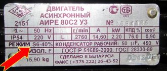
Each engine is equipped with a technical passport in the form of a riveted metal plate (nameplate), which shows the main characteristics of the engine. The engine type is indicated in the passport. As an example in Fig. Figure 6.7 shows the appearance of the type 4A100S2UZ engine nameplate.
How to determine power?
There are several ways to determine the power of an electric motor: by shaft diameter, by size and length, by current and resistance, by measuring with an electricity meter.
By overall dimensions
What dimensions need to be measured:
- Length, width, height of the case
- Distance from center of shaft to floor
- Shaft length and diameter
- Mounting dimensions for feet (flange)
By shaft diameter
Determining the power of an electric motor by shaft diameter is a common request for search engines. But this parameter is not enough to accurately determine - two engines of the same size, with the same shafts and rotation speed can have different power.
A table relating shaft diameters to power and speed for AIR and 4AM engines.
| Electric motor power P, kW | Shaft diameter, mm | |||
| 3000 rpm | 1500 rpm | 1000 rpm | 750 rpm | |
| 1,5 | 22 | 22 | 24 | 28 |
| 2,2 | 24 | 28 | 32 | |
| 3 | 24 | 32 | ||
| 4 | 28 | 28 | 38 | |
| 5,5 | 32 | 38 | ||
| 7,5 | 32 | 38 | 48 | |
| 11 | 38 | 48 | ||
| 15 | 42 | 48 | 55 | |
| 18,5 | 55 | 60 | ||
| 22 | 48 | 55 | 60 | |
| 30 | 65 | |||
| 37 | 55 | 60 | 65 | 75 |
| 45 | 75 | 75 | ||
| 55 | 65 | 80 | ||
| 75 | 65 | 75 | 80 | |
| 90 | 90 | |||
| 110 | 70 | 80 | 90 | |
| 132 | 100 | |||
| 160 | 75 | 90 | 100 | |
| 200 | ||||
| 250 | 85 | 100 | ||
| 315 | — |
According to the meter reading
Typically, meter measurements are displayed in kilowatts (hereinafter referred to as kW). For accurate measurements, you should turn off all electrical appliances or use a portable meter. The power of the electric motor is 2.2 kW, which means that it consumes 2.2 kW of electricity per hour.
To measure power using a meter reading you need:
- Connect the motor and let it run for 6 minutes.
- Multiply the meter measurements by 10 - we get the exact power of the electric motor.
Calculation of power by current
First you need to connect the motor to the network and measure the voltage readings. We measure the current consumption on each of the phase windings using an ammeter or multimeter. Next, we find the sum of the currents of the three phases and multiply them by the previously measured voltage indicators, clearly in the formula for calculating the power of the electric motor by current.
- P – electric motor power;
- U – voltage;
- Ia – 1st phase current;
- Ib – 2 phases;
- Ic – 3 phases.
Methodology for testing AC electric motors - scope and procedure
The established testing standards for AC electric motors provide for the following mandatory items:
- measuring insulation resistance using megohmmeters;
- checking the insulation condition under conditions of supplying test high voltage (industrial frequency) for 1 minute;
- checking DC resistance;
- assessment of the vibration level of bearings;
- measuring air gaps between the stator and rotor to check for compliance with acceptable values (unevenness should be no more than 10%);
- measuring the value of the axial run of the rotor;
- checking the air cooler by applying hydraulic pressure for ten minutes.
If deviations from the norms are not detected, the engine is tested in operation, first at idle and then under load.
Drying the electric motor
If the reduced resistance is caused by moisture getting on the motor or storage in a damp room, then the electric machine can be dried. To do this, you need to disassemble it - remove the bearing shield covers and remove the rotor. This is done to allow moisture to escape freely.
Advice! You can remove only one shield, and remove the rotor along with the second one.
After disassembly, drying is carried out in one of the following ways:
- By applying reduced voltage to the windings. The current should not exceed the rated current.
- Insert the heater into the stator. Most often, an incandescent lamp of 60-100W is used for this.
A day later, the insulation is re-measured. If the resistance increases, then the drying continues until it is completely dry; if not, then the engine is sent for medium repair to a specialized enterprise. This type of repair includes impregnation of the windings with varnish and repeated drying.
Insulation testing is a necessary part of motor testing. The types of inspections in some cases are determined by the PUE and other regulatory documents.
Motor insulation
When testing an electric motor after repair or storage in a warehouse, one of the important parameters is the insulation resistance.
Measuring the insulation resistance of an electric motor
Insulation testing is carried out in different ways.
Megger insulation test
Resistance is measured using a mechanical or electronic megger.
Important! Checking the insulation of motors up to 380V is carried out with a 500-volt device, and from 0.4 to 1 kV with a 1000V device.
Before checking the insulation resistance, the electrical machine is inspected for damage to the housing. A wet electric motor must be dried before testing. It is advisable to disconnect all windings from each other to check the insulation between them.
Procedure for measuring insulation resistance:
- connect the output or set the switch to the “megaohm” position;
- check the megohmmeter by connecting the ends together and taking a short-term measurement;
- the result should be about “0”;
- connect one of the wires to the coil being tested, and the other to a part of the housing that has been cleared of paint or to another winding;
- for 15-60 seconds, rotate the handle of the device at a frequency of 120 rpm;
- without stopping rotating the handle, check the instrument readings.
The winding and the housing or two windings with insulation between them constitute a capacitor. When measuring, this capacitor is charged to the megger voltage - 500 or 1000 volts. Therefore, after checking, the terminals of the electrical machine and the device output must be short-circuited with each other.
Checking the turn-to-turn insulation of windings
This type of test is carried out to check the insulation between the turns of the coils of asynchronous electric machines.
To do this, after acceleration, a squirrel-cage motor rotating at idle is connected to an increased voltage.
This voltage is 30% higher than the nominal voltage, and the operating time in such conditions is 3 minutes. The machine is turned on through ammeters installed on each phase.
After the tests, the voltage is reduced to the nominal value and the device is turned off.
Important! The voltage is increased and decreased smoothly using an adjustable autotransformer or an electronic power supply.
If noise, knocking, smoke or “floating” ammeter readings appear, the electric motor is turned off and sent for repair.
Tests of an electric machine with a wound rotor are carried out in a braked state with the rotor turned off.
AC High Voltage Insulation Test
This test is carried out using a transformer that has smooth voltage regulation on the secondary winding side.
The circuit of the test device also provides a circuit breaker with a maximum protection setting value sufficient to shut down the installation in emergency situations.
The secondary winding is connected to the windings of the electric machine and the housing.
The test duration is 1 minute when checking the insulation between the windings and the housing and 5 minutes when testing the insulation between the windings. To carry out an inter-winding test, voltage is applied to one of the windings, and the rest are connected to the housing.
The voltage rises and falls smoothly within 10 seconds from 50% Un to 200% Un.
Insulation resistance standards for electrical machines
The PUE (electrical installation rules) regulates the insulation resistance of electric motors depending on the design and power of the device.
Permissible resistance when testing the insulation of asynchronous electric machines
When measuring the insulation of asynchronous motors, the star or delta connection of the stator windings must be disassembled and each coil must be checked relative to the housing and to each other. Tests are carried out at a machine temperature of 10-30°C.
The insulation resistance should be:
- in the stator no less than 0.5 mOhm;
- in a wound rotor no less than 0.2 mOhm;
- The minimum insulation resistance of temperature sensors is not standardized.
In order not to use the reference book, the usually acceptable resistance is considered to be 1 mOhm. Smaller values indicate minor violations that will eventually lead to failure of the electric machine.
Important! In order to avoid such a situation, it is advisable to send the device to a specialized enterprise for medium repairs.
DC Motor Insulation
To check the insulation in DC machines, it is necessary to remove the brushes from the brush holders or place insulating material under them.
The measurement is carried out between different parts of the electrical machine circuit:
- field windings and armature commutator;
- brush holder and device body;
- armature commutator and housing;
- field windings and electrical machine housing.
Important! If possible, the field winding coils are disconnected from each other and checked separately.
The minimum permissible insulation resistance depends on the temperature and rated voltage of the electrical machine. At 20°C it is:
- 220V - 1.85 mOhm;
- 440V - 3.7 mOhm;
- 660V - 5.45 mOhm.
In addition to the windings and armature, the resistance of the excitation and armature winding bands is measured. It is checked between the bandage itself and the body, as well as the winding secured by it. It should not be less than 0.5 mOhm.
Reasons for low resistance
There are several reasons for low insulation resistance.
Electric machine overheating
This situation occurs due to an overload of the electric machine or a break in one of the phases in three-phase electric motors. It is impossible to eliminate this problem in a workshop and the device must be sent to a specialized enterprise to replace the windings.
Protection devices help prevent such a malfunction:
- The thermal relay turns off the electric machine when overloaded;
- The voltage relay turns off the installation if one of the phases is missing or the network voltage is low.
Important! For better protection, temperature sensors are built inside electric motors. In new machines they are installed during manufacture, and in old machines such devices can be installed during planned or major repairs.
Drying the electric motor
If the reduced resistance is caused by moisture getting on the motor or storage in a damp room, then the electric machine can be dried. To do this, you need to disassemble it - remove the bearing shield covers and remove the rotor. This is done to allow moisture to escape freely.
Measuring the gaps between the steel of the rotor and stator.
The size of the air gaps is determined using a special set of calibrated feelers (plate - for measuring gaps up to 2mm and wedge - for gaps up to 20mm). Measurements are made in the intergland space. The width of the probe should be used less than the width of the teeth, and when taking measurements, the probe should not fall on the grooved wedge or bandage. For AC electric motors, measurements are made at several diametrically opposite points - four or eight, depending on the size of the motor. With a short length of active steel (up to 300 mm), the gaps can be measured on one side, with a longer length - on both sides. The average gap is equal to the ariphretic mean value of the measured gaps. In large electric motors, the air gap in the lower part is allowed to be 0.1÷0.3 mm larger than in the upper part.
The dimensions of the air gaps at diametrically opposite points or points shifted by 90 relative to the rotor axis should differ by no more than 10% of the average size.
ELECTRICIAN
2. Power frequency high voltage test.
Tests of the electrical strength of the insulation of the windings relative to the housing and between the windings are carried out with a sinusoidal alternating voltage with a frequency of 50 Hz, using the AID-70 installation. Test duration is 1 minute.
The test voltage is applied to each phase of the winding, with the motor housing and two other phases grounded. If it is impossible to isolate the phase under test, all 3 phases are tested simultaneously, relative to the motor housing. Test voltages for AC motor windings are given in table. 5.4. RD 34.45-51.
Tests must be carried out by persons who have undergone special training and have practical experience in conducting tests.
Before starting the test, it is necessary to check the stationary grounding of the housings of the equipment under test and reliably ground the test installation. The test site, as well as connecting wires under test voltage, must be fenced or an observer must be posted at the test site.
The wire by which the increased voltage from the test installation is supplied to the equipment under test must be securely secured using intermediate insulators, insulating hangers, etc., so that this wire is not accidentally brought close to live parts under operating voltage or the air gaps are reduced. , which must be at least the following values:
Test voltage, kV up to 20 30 40 50 60
Distance to grounded objects, cm 5 10 20 25 30
to live parts, cm 25 25 30 30 35
Connection of the installation to a 380/220 V network must be carried out through a switching device with a visible break; connection through a plug located at the test installation is allowed.
When assembling the test circuit, first of all, the protective and operational grounding of the test installation is carried out. Before connecting the test installation to a 380/220 V network, grounding is applied to the high voltage terminal of the installation using a special grounding rod. The cross-section of the copper wire with which the terminal is grounded must be at least 4 mm2.
Before applying the test voltage to the test installation, the workman is obliged to:
- check whether all members of his team are in the places indicated by the work manufacturer, whether unauthorized persons are removed, whether it is possible to apply test voltage to the equipment;
- warn the team about the supply of voltage with the words “Voltage is applied” and, making sure that the warning is heard by all members of the team, remove the ground from the terminal of the test installation and apply 280/220 V voltage to it.
From the moment the ground is removed, the entire test installation, including the equipment under test and connecting wires, is considered to be live, and it is prohibited to make any reconnections in the test circuit or on the equipment under test.
After completion of the tests, the workman must reduce the voltage of the test installation to zero, disconnect it from the 380/220 V network, ground (or give orders to ground) the terminal of the installation and inform the team about this with the words “Voltage removed.” Only after this can the wires be reconnected at the test facility or, if the test is completely completed, can they be disconnected and the guards removed.
Before the insulation test, as well as after the test, it is necessary to discharge the equipment under test to the ground and ensure that there is no charge on it. The application and removal of grounding by a grounding rod, the connection and disconnection of wires from the test installation and the equipment under test must be carried out by the same person and carried out using dielectric gloves.
The wire connecting the test installation with the equipment under test must be removed from electrical equipment under operating voltage up to 10 kV at a distance of at least 1 m.
Motor design
In order to quickly master how to check an electric motor, you need to clearly understand the structure of the main parts. HOW TO CHECK How to ring a three-phase motor with a tester. All motors are based on two parts of the structure: the rotor and the stator. The 1st component always rotates under the influence of the electric field, the 2nd component is motionless and just creates this vortex flow.
To understand how to check an electric motor, you will need to disassemble it at least once with your own hands. The design of different manufacturers is different, but the principle of diagnosing the electrical part remains constant. There is a gap between the rotor and stator, in which small iron shavings can accumulate when the housing is depressurized.
When bearings wear out, they can produce excessive current characteristics, as a result of which the protection will be knocked out. How to test a motor with a multimeter. When dealing with the question of how to check an electric motor, one should not forget about mechanical damage to the moving parts and the parts where the contacts are located.
When is it necessary to check the insulation resistance of an electric motor?
The current regulatory documents indicate that if the machine is stationary, it must be examined at least once every two years. If the device is portable, then it is worth reducing the interval between tests to 6 months.
It should also be noted that medical devices must be tested once every three months. Experienced experts say that checking the cable insulation should be carried out immediately after a major overhaul - this is also true for various motors.
In addition, checking the insulation resistance of the electric motor will also be necessary when moving the unit to another facility and connecting it to an installation with different characteristics and design. Finally, we should not forget to check immediately after removing the unit from storage or long-term storage without starting it up.
Example of a technical report for non-residential premises
Back
Forward
Insulation resistance standards for electrical machines
The PUE (electrical installation rules) regulates the insulation resistance of electric motors depending on the design and power of the device.
Permissible resistance when testing the insulation of asynchronous electric machines
When measuring the insulation of asynchronous motors, the star or delta connection of the stator windings must be disassembled and each coil must be checked relative to the housing and to each other. Tests are carried out at a machine temperature of 10-30°C.
The insulation resistance should be:
- in the stator no less than 0.5 mOhm;
- in a wound rotor no less than 0.2 mOhm;
- The minimum insulation resistance of temperature sensors is not standardized.
In order not to use the reference book, the usually acceptable resistance is considered to be 1 mOhm. Smaller values indicate minor violations that will eventually lead to failure of the electric machine.
Important! In order to avoid such a situation, it is advisable to send the device to a specialized enterprise for medium repairs.
DC Motor Insulation
To check the insulation in DC machines, it is necessary to remove the brushes from the brush holders or place insulating material under them.
The measurement is carried out between different parts of the electrical machine circuit:
- field windings and armature commutator;
- brush holder and device body;
- armature commutator and housing;
- field windings and electrical machine housing.
Important! If possible, the field winding coils are disconnected from each other and checked separately. The minimum permissible insulation resistance depends on the temperature and rated voltage of the electrical machine
At 20°C it is:
The minimum permissible insulation resistance depends on the temperature and rated voltage of the electrical machine. At 20°C it is:
In addition to the windings and armature, the resistance of the excitation and armature winding bands is measured. It is checked between the bandage itself and the body, as well as the winding secured by it. It should not be less than 0.5 mOhm.
Insulation resistance standards
As with other elements of electrical equipment, for electric motors and similar DC machines, there are limit values for the conductivity of protective insulation. If the actual indicator turns out to be below the permissible limit when measured, the unit is removed from service.
Standards for asynchronous motors
According to the PUE, when measuring the insulation resistance of electric motor windings, the specific design and declared power of the unit should be taken into account. Only after all these factors have been taken into account can you begin to measure the controlled parameter
Taking these factors into account, the indicator being checked must correspond to the following values:
- For stator windings - at least 0.5 mOhm;
- For the motor rotor - at least 0.2 mOhm;
- The indicator for thermal sensors is not standardized.
Additional information: An approximate estimate, often used in measurement practice, is based on a value of this indicator not lower than 1 mOhm.
Its decrease to 0.5 mOhm, for example, indicates minor deviations from the norm, which, nevertheless, lead to serious consequences over time. If a significant decrease in this indicator is detected, it is best to send the questionable unit for examination to a specialized workshop.
Standards for DC machines
Testing techniques for DC machines are somewhat different from the procedures already discussed for asynchronous motors. Here you will first need to remove the brushes from the brush holders (alternatively, place a piece of insulating material under their body).
Checking the minimum insulation resistance is organized between the following nodes and circuit elements:
- between all exciting windings and the collector;
- between the brush holder and the base (body) of the unit;
- between the armature collector and the base;
- as well as between the exciting windings and the unit body.
Important! During the test, the field coils are electrically disconnected from other components and each is checked individually.
The permissible insulation resistance is determined by a number of factors, the main of which are the operating voltage of the unit and the air temperature. With an average of 20°C, it corresponds to the following values:
- at 220 Volts supply – 1.85 mOhm;
- at 380 or 440 Volts - 3.7 mOhm;
- in the case of a voltage of 660 Volts - 5.45 mOhm (the same indicator is provided for high-voltage machines of 6 kV or 10 kV).
In addition to the nodes considered, the resistance of the bandages is controlled. It is measured between itself and the housing, and, in addition, between it and the fixed motor winding. This indicator cannot be less than 0.5 mOhm.
Monitoring the heating temperature of electric motors
The permissible heating of electric motors depends on the insulation class of the windings. The transition to a higher class of electric motor insulation can only be carried out during a major overhaul.
Attention. You need to know that with an increase in the temperature of electric motor windings above permissible values, the service life of the insulation is sharply reduced
The ambient temperature at which the electric motor can operate at rated power is considered to be 40 °C. When the ambient temperature rises above 40 °C, the load on the electric motor must be reduced so much that the temperature of its individual parts does not exceed permissible values. The maximum permissible temperature rises of the active parts of electric motors and at an ambient temperature of 40 ° C should not exceed:
— 65 °C — for class A insulation;
— 80 °C — for class E insulation;
— 90 °C — for insulation class B;
— 110 °C — for class G insulation;
— 135 °C — for class H insulation.
For asynchronous motors, as the supply voltage decreases, the power on the motor shaft decreases. In addition, a decrease in voltage below 95% of the rated voltage leads to a significant increase in motor current and heating of the windings.
An increase in voltage above 110% of the rated voltage also leads to an increase in the current in the motor windings, and stator heating due to eddy currents increases.
Attention. Regardless of the decrease in ambient temperature, it is not allowed to increase current loads by more than 10% of the nominal
AC motor testing
AC electric motors [5] are electrical machines that convert electrical energy into mechanical energy, and are also the most advanced and widespread type of drive for machines and mechanisms that convert electrical energy into mechanical energy.
Insulation resistance measurement. [6] Produced by a megohmmeter, the voltage of which is indicated in the table. 2.1. Acceptable values of insulation resistance and absorption coefficient R
60″ /
R
15″ are indicated in the table. 2.1-2.3.
Assessment of the insulation condition of electric motor windings when deciding on the need for drying. [7] AC electric motors are switched on without drying if the values of winding insulation resistance and absorption coefficient are not lower than those indicated in the table. 2.1-2.3
Power frequency high voltage test. The test voltage value is taken according to table. 2.4. The duration of test voltage application is 1 min.
DC resistance measurement. The measurement is taken when the machine is practically cold.
Stator and rotor windings. [8] The direct current resistance of the rotor winding is measured for synchronous electric motors and asynchronous electric motors with a wound rotor. The measurement is made for electric motors with a voltage of 3 kV and higher. Reduced to the same temperature, the measured resistance values of the various phases of the windings, as well as the field windings of synchronous motors, should not differ from each other and from the original data by more than 2%.
Table 2.1
Acceptable values of insulation resistance and absorption coefficient
| Test element | Type of measurement | Megaohm meter voltage, V | Permissible value of insulation resistance, MOhm, and absorption coefficient | Note |
| 1. Stator winding | P | 2500/1000/ /500** | In accordance with the instructions in table. 2 2. | |
| K, T | For electric motors in operation, the permissible values of insulation resistance R 60″ and the absorption coefficient are not standardized, but must be taken into account when deciding whether to dry them | In operation, determination of the absorption coefficient R 60″/ R 15″ is mandatory only for electric motors with voltages above 3 kV or power more than 1 MW | ||
| 2. Rotor winding | P | 1000 (500 allowed) | 0,2 | The measurement is carried out for synchronous electric motors and electric motors with phase |
| K, T | — | rotor for voltage 3 kV and higher or power more than 1 MW | ||
| 3. Thermoin indicators with connecting wires | P, K | 250 | — | |
| 4. Bearings | P, K | 1000 | — | The measurement is carried out on electric motors with voltages of 3 kV and above, the bearings of which are insulated relative to the housing. The measurement is made relative to the foundation slab with the oil lines fully assembled. In operation, measurement is carried out during repairs with removal of the rotor |
During routine repairs, it is measured if this does not require special dismantling work.
Insulation resistance is measured at a rated winding voltage up to 0.5 kV inclusive with a 500 V megohmmeter, at a rated winding voltage above 0.5 kV to 1 kV - with a 1000 V megohmmeter, and at a rated winding voltage above 1 kV - with a voltage megohmmeter 2500 V.
Table 2.2
Acceptable values of insulation resistance and absorption coefficient for stator windings of electric motors
| Power, rated voltage of the electric motor, type of winding insulation | Criteria for assessing the state of stator winding insulation | |
| Insulation resistance value, MOhm | Absorption coefficient value R 60″/ R 15″ | |
| 1. Power over 5MW, thermoset and mica compound insulation | According to the conditions for switching on synchronous generators, clause 3.2. | |
| 2. Power 5 MW and below, voltage above 1 kV, thermosetting insulation | At a temperature of 10-30°C, the insulation resistance is not lower than ten megaohms per kilovolt of rated line voltage | Not less than 1.3 at a temperature of 10-30°C |
| 3. Motors with mica compound insulation, voltage over 1 kV, power from 1 to 5 MW inclusive, as well as motors of lower power for outdoor installation with the same insulation with voltage over 1 kV | Not lower than the values indicated in the table. 2.3 | Not lower than 1.2 |
| 4. Motors with mica compound insulation, voltage over 1 kV, power less than 1 MW, except as specified in clause 3 | Not lower than the values indicated in the table. 2.3. | — |
| 5. Voltage below 1 kV, all types of insulation | Not lower than 1.0 MOhm at a temperature of 10-30°C | — |
Table 2.3
Lowest permissible insulation resistance values for electric motors (Table 5.2, paragraphs 3 and 4)
| Winding temperature, °C | Insulation resistance R 60″, MOhm, at rated winding voltage, kV | ||
| 3-3,15 | 6-6,3 | 10-10,5 | |
| 10 | 30 | 60 | 100 |
| 20 | 20 | 40 | 70 |
| 30 | 15 | 30 | 50 |
| 40 | 10 | 20 | 35 |
| 50 | 7 | 15 | 25 |
| 60 | 5 | 10 | 17 |
| 75 | 3 | 6 | 10 |
Table 2.4
Power frequency test voltages for AC motor windings
| Test element | Type of test | Electric motor power, kW | Rated voltage of the electric motor, kV | Test voltage, kV |
| 1. Stator winding*** | P | Less than 1.0 | Below 0.1 | 0.8 (2 U nom+0.5) |
| From 1.0 to 1000 | Below 0.1 | 0.8 (2 U nom+1) | ||
| Above 0.1 | 0.8 (2 U nom+1), but not less than 1.2 | |||
| From 1000 or more | Up to 3.3 inclusive | 0.8 (2 U nom+1) | ||
| From 1000 or more | Over 3.3 to 6.6 inclusive | 0.8 2.5 U nom | ||
| From 1000 or more | Over 6.6 | 0.8 ( U nom+3) | ||
| TO | 40 or more, and | 0.4 and below | 1,0 | |
| electric motors | 0,5 | 1,5 | ||
| responsible | 0,66 | 1,7 | ||
| mechanisms* | 2,0 | 4,0 | ||
| 3,0 | 5,0 | |||
| 6,0 | 10,0 | |||
| 10,0 | 16,0 | |||
| Less than 40 | 0.66 and below | 1,0 | ||
| 2. Rotor winding of synchronous electric motors intended for direct starting, with an excitation winding, | P | — | — | 8 times U nom of the excitation system, but not less than 1.2 and not more than 2.8 |
| shorted to a resistor or power supply | TO | — | — | 1,0 |
| 3. Rotor winding of an electric motor with a wound rotor | P, K | — | — | 1.5 U р**, but not less than 1.0 |
| 4. Field suppression circuit resistor for synchronous motors | P, K | — | — | 2,0 |
| 5. Rheostats and starting resistors | P, K | — | — | 1.5 U р**, but not less than 1.0 |
The test must be carried out during a major overhaul (without changing the windings) immediately after stopping the electric motor until it is cleaned of contamination.
Uр is the voltage on the rings with the stationary rotor open and full voltage on the stator.
With the permission of the technical manager of the enterprise, testing of motors with voltages up to 1000 V may not be carried out during commissioning.
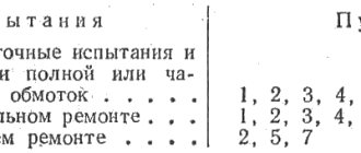
Rheostats and starting adjustment resistors. [9] For rheostats and starting resistors installed on electric motors with a voltage of 3 kV and above, the resistance is measured on all branches. For electric motors with voltages below 3 kV, the total resistance of rheostats and starting resistors is measured and the integrity of the taps is checked. The resistance values should not differ from the original values by more than 10%. During major repairs, the integrity of the circuits is checked.
Measuring the air gap between the steel of the rotor and stator. Gap measurements should be carried out if the design of the electric motor allows. At the same time, for electric motors with a power of 100 kW or more, for all electric motors of critical mechanisms, as well as for electric motors with remote bearings and plain bearings, the size of the air gaps is in places located along the circumference of the rotor and shifted relative to each other by an angle of 90°, or in places specially provided during the manufacture of the electric motor, should not differ by more than 10% from the average value.
Measuring clearances in plain bearings. The increase in clearances in plain bearings exceeds the values given in table. 2.5, indicates the need to refill the liner.
Table 2.5
Permissible clearance values in electric motor plain bearings
| Nominal | Gap, mm, at rotation speed, rpm | ||
| shaft diameter, mm | Up to 1000 | From 1000 to 1500 (inclusive) | Over 1500 |
| 18-30 | 0,04-0,093 | 0,06-0,13 | 0,14-0,28 |
| 31-50 | 0,05-0,112 | 0,075-0,16 | 0,17-0,34 |
| 51-80 | 0,065-0,135 | 0,095-0,195 | 0,2-0,4 |
| 81-120 | 0,08-0,16 | 0,12-0,235 | 0,23-0,46 |
| 121-180 | 0,10-0,195 | 0,15-0,285 | 0,26-0,53 |
| 181-260 | 0,12-0,225 | 0,18-0,3 | 0,3-0,6 |
| 261-360 | 0,14-0,25 | 0,21-0,38 | 0,34-0,68 |
| 361-600 | 0,17-0,305 | 0,25-0,44 | 0,38-0,76 |
Checking the operation of the electric motor at idle or with the mechanism unloaded. [10] Produced for electric motors with voltages of 3 kV and higher. The idle current value for newly introduced electric motors is not standardized. The current value XX after a major overhaul of the electric motor should not differ by more than 10% from the current value measured before its repair, with the same voltage at the stator terminals. The duration of checking electric motors must be at least 1 hour.
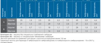
Vibration measurement of electric motor bearings. The measurement is carried out on electric motors with voltages of 3 kV and above, as well as on all electric motors of critical mechanisms. The vertical and transverse components of vibration (root mean square value of vibration velocity or range of vibration displacements), measured on the bearings of electric motors articulated with mechanisms, must not exceed the values specified in the factory instructions. In the absence of such instructions in the technical documentation, vibration of bearings of electric motors articulated with mechanisms should not exceed the following values:
| Synchronous rotation speed, rpm | 3000 | 1500 | 1000 | 750 or less |
| Vibration of bearings, microns | 30 | 60 | 80 | 95 |
The frequency of vibration measurements of components of critical mechanisms during the overhaul period must be established according to a schedule approved by the technical manager of the power plant.
Measuring the rotor run-up in the axial direction. [11] Measurement is carried out on electric motors with plain bearings. The axial run-up of the motor rotor, not connected to the mechanism, depends on the design of the motor, is given in the technical documentation for the motor and should be from 2 to 4 mm on the side of the neutral position1, determined by the action of the magnetic field when the rotor rotates in steady state and fixed with a mark on the shaft . The rotor run-up is checked during major repairs of electric motors of critical mechanisms or in the event of removal of the rotor.
Checking the operation of the electric motor under load. The test is carried out at a constant power consumed by the electric motor from the network, at least 50% of the rated value, and at a corresponding steady temperature of the windings. The thermal and vibration condition of the engine is checked.
Hydraulic test of the air cooler. The test is carried out with an excess pressure of 0.2-0.25 MPa for 5-10 minutes, unless there are other instructions from the manufacturer.
Checking the serviceability of the squirrel-cage rotor rods. [12] Checking is carried out for asynchronous electric motors during major repairs by inspecting the removed rotor or by special tests, and during operation, as necessary, by pulsations of the working or starting stator current.
Test standards for AC electric motors during winding repairs are given in the Appendix.
Reasons for low resistance
There are several reasons for low insulation resistance.
Electric machine overheating
This situation occurs due to an overload of the electric machine or a break in one of the phases in three-phase electric motors. It is impossible to eliminate this problem in a workshop and the device must be sent to a specialized enterprise to replace the windings.
Protection devices help prevent such a malfunction:
- The thermal relay turns off the electric machine when overloaded;
- The voltage relay turns off the installation if one of the phases is missing or the network voltage is low.
Important! For better protection, temperature sensors are built inside electric motors. In new machines they are installed during manufacture, and in old machines such devices can be installed during planned or major repairs.
Hazards indicated by motor insulation resistance measurements
If the level of the measured indicator drops below the permissible value, you should immediately stop using the device. The engine will remain operational, but if an unforeseen situation occurs, a strong current leak will occur, which poses a danger to human health and the safety of valuable property. Such a leak can also cause a fire to spread indoors.
Therefore, if measuring the insulation resistance of electric motors confirms that the protective layer does not meet existing requirements, the device should be stopped and completely discharged before dismantling; restarting even for a short time is prohibited in order to avoid injury to a person by stray currents generated by a very powerful electromagnetic field.
Below you can use the online calculator to calculate the cost of electrical laboratory services.