Fiber optic cable has long been firmly established in our lives, gradually replacing all other brands of wires previously widely used in low-current networks and telecommunications networks.
At the same time, for some reason, everyone has it firmly ingrained in their heads that working with optics requires some kind of super-professionals and that learning how to splice optical fibers takes a very long time and diligently.
Meanwhile, manufacturers of welding machines say exactly the opposite. They claim that their modern devices are so advanced and easy to use that anyone can handle this process.
It is enough to follow certain instructions, not make basic mistakes, and the miracle device will do most of the work for you on its own.
Is this really true or not? In order to objectively answer this question, an important remark should be made - welding itself is only 5% of the total work of a fiber-optic cable operator.
Having studied only the welding process, without the appropriate knowledge of reading diagrams, building highways, skills in cutting and laying cables into cassettes and cross-connects, and measuring attenuation with a reflectometer, you will never be considered a professional in your field.
But let’s take a closer look at the process of welding, preparing the cable for it and note the most common errors that sadly affect the connection point, signal level and further operation of the fiber-optic line.
Types of fiber optic cable
Welding machines for optics work on approximately the same principle. Therefore, we will not focus on any one model, the good old Fujikura or Ilsintech, but will study the sequence of the process itself.
You may even have a smartphone-controlled model. But this does not fundamentally change the technology of work. It's the same everywhere.
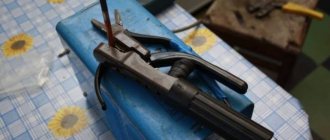
So, initially we have two sections of fiber optic cable from which we need to remove the outer insulation.
When removing the outer shell, do it in such a way that in the future you will not have problems with laying fibers and modules in a splice cassette, cross-connect or coupling.
Mistake #1
If the cable has been lying in the open air for a long time (without a protective cap), about 1 m from each end must be cut off before cutting.
The fact is that the threads in the cable, like a sponge, absorb all the surrounding moisture. As a result, the optical fiber becomes cloudy.
And even if you make the connection perfectly, it still won’t save you from large signal losses in the future.
Turn on the device and set on it the type of cable that will be connected.
There are single-mode (SM) and multimode (MM) optical cables.
Single-mode fibers generally use three wavelengths (three transparency windows):
- 850nm
- 1310nm
- 1550nm
It all depends on the total length of the route and the equipment used. In addition, fibers are divided into:
- regular – SM
- with shifted dispersion - DS
- with non-zero biased dispersion - NZ
Outwardly there is no way to distinguish them. When welding, they most often work with simple and offset ones. It is not recommended to combine offset and simple fibers.
Computer repair in Samara
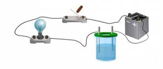
A digital optical audio cable is used to carry a compressed digital audio signal from a source (computer or CD player) to a receiver or speaker system.
Optical audio cable is good for short distances where there is a high risk of radio frequency interference (interference). Such a cable does not use electricity to transmit a digital signal from a source to a receiver, so it is not a source of interference in itself, produces less distortion of sound on a computer, and also allows for galvanic isolation of electronic devices. Typically, an audio cable using optical fiber uses the S/PDIF audio interface format, which in its full name means Sony/Phillips Digital Interconnect Format. There is another version of this interface based on a coaxial cable. It is worth noting here that the optical interface is very convenient for transmitting multi-channel sound over one speaker cable, which is impossible with other classic types of connection. This is facilitated by the use of multimode optical fiber. Instructions
1. Install all drivers and application software that came with the sound or motherboard, according to the manufacturer's instructions. This will allow the computer and external audio receiver to correctly identify the optical connection at the time of connection. This step won't have to be performed on consumer audio devices that are specifically designed to operate over an optical cable. For example, a digital home theater has a built-in electronic circuit that independently determines when a signal is connected via an optical audio cable.
2. Connect one end of the fiber optic audio cable to the source port (on your computer or external sound card) via an S/PDIF connector. This connector is a rectangular port that is compatible with the audio cable connector and is tamperproof.
3. Connect the other end of the optical cable to a digital audio receiver port, such as a receiver. Typically on consumer audio devices this port is designated as “S/PDIF”, “Optical Digital” or “TOSLINK”.
4. Disconnect all other audio cables connecting devices (coaxial cables) as the audio system may continue to use them by default. Or use the input selector on your amplifier. We advise you to read an interesting article on how to enable sound in safe mode.
Stripper for stripping insulation from optical cable
Next, you need to remove the insulation from the modules and individual cores. Most often, a special hand tool is used for this - an optical stripper.
Although in some models of welders you can also find a built-in thermal stripper. However, mechanical work is much more convenient and faster.
Especially when you cook not at a comfortable table, but somewhere at a height or in a well.
Mistake #2
Remember, such a tool, in a good way, must have a factory adjustment.
Otherwise, the whole process may turn not into a neat cut, but into scratching or roughly tearing off the shell.
If the varnish coating on the fibers is not removed the first time and you have to use the stripper back and forth, this says a lot about the quality of the tool.
First, the insulation is removed from the modules. Before this, the hydrophobic coating is removed from them with a cloth soaked in alcohol.
It is recommended to do this with gloves. Hydrophobe is a very unpleasant thing, which is difficult to wash off in the future.
And after that you still have to work with thin optical fiber and a welder!
Mistake #3
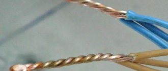
When removing the sheathing from the wires, do not do it as shown below.
Optical fiber is a strong material that can be broken, but not broken! When cutting in sub-zero temperatures, the core can easily break using this method.
Therefore, it is better to remove the insulation with a stripper, pulling it out from each vein in turn, and only after that move on to the next one, avoiding sharp bends and creases.
After removing the outer insulation, the varnish coating is removed from the fiber. It gives it both flexibility and rigidity.
Without it, the fiber becomes very fragile. You can put a mobile phone on such a vein without varnish and it will break. But with varnish it’s a completely different matter.
It happens that the cable hangs for weeks only on these threads in the varnish, when the entire outer sheath is already damaged. And at least the optical fiber can withstand wind and tensile loads.
Mistake #4
When you strip the fiber from varnish, some of it remains on the stripper.
Because of this, you can accidentally break or scratch the next fiber, which will affect the quality of the weld. Therefore, when moving on to stripping the next vein, each time remove all excess from the blades.
Mistake #5
The optical stripper is prohibited from cutting through anything other than fiber-optic communication lines.
It is designed specifically for 125 micron fiber optic cores. Bite off the plastic tie with it and you can go buy another tool.
Mistake #6
Also, when cleaning, make sure that the welding machine is closed and that no foreign cuttings or debris get there.
Fujikura welder tested in dusty and humid conditions
By the way, when many welders become dusty, it is even forbidden to blow them with compressed air.
They have very sensitive mechanics installed and a strong air flow can disrupt the factory settings.
Comparison with HDMI
Modern manufacturers provide a wide choice when connecting audio devices through a home theater. As a result, you can get amazing results. The most popular method at the moment is connecting via an HDMI cable. This way you can transmit not only audio, but also the video signal is transmitted in high resolution.
When equipment with such an interface appeared on the market, optical fiber and its audio output faded into the background, since the wire can only transmit an audio signal, and separate switching is required for video.
But, despite the fact that the connection standard has been in use for 30 years, it is still relevant today. Optical wire is still used to switch up to 7.1 channels of high-resolution audio.
The wire is used due to the use of conventional receivers that have high quality and an optical input on the port. If a person loves good sound on his TV, it makes no sense for him to replace these devices with new ones. It is worth noting that most players or HDTVs and game consoles still use an optical port.
Optical fiber cleaver
After removing the varnish layer from the fiber, it must be wiped with a lint-free cloth soaked in alcohol.
Mistake #7
When cleaning the next fiber, it is recommended to use a different cloth, or at least that part of it that was not involved in the previous cleaning, or did not come into contact with your fingers.
If the core is perfectly clean, when wiping it with a napkin, you should hear a characteristic creaking sound.
Mistake #8
From this moment on, you should never touch the fiber with your hands or anything else.
Moreover, until you place it in the welding machine, not even a speck of dust should settle on it. This all affects the quality of welding and the level of losses.
After this, the fiber must be cut perfectly evenly.
Mistake #9
This cannot be done with any other tool other than a special cleaver.
Although in the USSR, in the early stages of the development of optics, even such a universal fiber optic cable set was used.
The cut should be very clear, have a strictly cylindrical shape, without any corners or chips.
The cleaver can either be built into the welding machine or be a separate tool. The second option is preferable.
Simply place the wires in the cleaver and close the lids until they click.
Mistake #10
Attention - remnants and cut pieces of optical fiber must be collected in a separate container.
They must not fall on the floor, on the table, or get anywhere else. The thickness of these veins is so small that once this piece gets under your skin, it can penetrate a vein and begin its journey throughout the body. It can also be accidentally inhaled into the lungs.
All this will ultimately lead to dire consequences.
Many people solve the problem of collecting scraps using ordinary pieces of electrical tape. Cheap and cheerful.
Mistake #11
After chopping, the fiber can no longer be wiped with alcohol or touched anything with it.
Even being with him in dusty or unsanitary conditions is prohibited. Create a suitable work place for this (tent, drag and hide the cable in the car, etc.).
Installation of optical cable fibers
Installation of OK fibers is the most critical operation that determines the quality and range of communication over optical cable lines. The connection of fibers and installation of cables is carried out both during the production process and during the construction and operation of cable lines.
When installing OK, the following must be ensured: high moisture resistance of the joint, reliable mechanical characteristics for tearing and crushing, and stability of the characteristics of the joint during long-term operation in underground conditions.
Installation of OK fibers is divided into permanent (stationary) and temporary (detachable). Permanent installation is carried out on stationary cable lines laid for a long time, and temporary installation is carried out on mobile lines, where construction lengths of cables have to be repeatedly connected and disconnected [14].
An optical fiber connector, as a rule, is a fitting designed to align and fix the fibers being connected, as well as mechanically protect the splice. The main requirements for connecting devices are simplicity of design, low transient losses, resistance to external mechanical and climatic influences, and reliability. In addition, detachable connectors are subject to requirements for stability of parameters during multiple docking [14, 15].
The main task of connecting optical fibers is to ensure their strict alignment, identical geometry of the ends, perpendicularity of the surfaces of the latter to the optical axes of the fibers and a high degree of smoothness of the ends. This assumes that the surface of the ends is flat.
An important requirement is also high stability of the optical contact state and low losses introduced by the splice. Violation of these conditions creates reflections, impairs the use of the radiation field of the end of the exciting fiber, i.e., reduces the efficiency of input into the excited fiber. In addition, a poor-quality optical contact represents inhomogeneity, the effect of which on signal propagation depends on the degree of imperfection of the contact and the number of modes (increasing with a decrease in their number) [14, 15].
Installation of a dead-end coupling MTOC 96/48-O1-IV on optical communication cables. The MTok 96/48-O1-IV dead-end coupling is designed for splicing the construction lengths of trunk and intra-zone optical communication cables laid in plastic pipes and suspended on power transmission line supports, as well as supports of the contact network and automatic blocking of railways [25].
In addition to the main area, MTOC 96/48-O1-IV couplings can be mounted on optical cables (OK) laid in cable ducts, collectors, tunnels and in technical rooms of industrial and residential buildings.
The coupling is designed for splicing optical cables with modular cores or with cores in the form of central tubes.
Features of the design, configuration and installation of the coupling. The MTOC 96/48-O1-IV coupling has three round pipes and one oval. When installing the coupling in the “straight coupling” version, two OKs are inserted into two round pipes. When installing the coupling in the “branch coupling” version, three OKs are inserted into the round pipes and two more through the oval pipe. An option is possible with the introduction of four OKs without armor through an oval pipe. When installing a coupling in the “branch coupling with transit” option, a loop of transit modules of the main cable is inserted into an oval pipe, and branch cables are inserted into round pipes [25].
To store the supply of optical fibers and fix the KDZS protective sleeves, two KU-M-O1 cassettes with 24 optical fibers each are used. In Fig. 2.45. The assembly design of the MTok 96/48 coupling is shown.
Rice. 2.45. Clutch assembly:
1 — headband; 2 – clamp; 3 - casing; 4 - latch; 5 - latch.
Cable entries are sealed using pieces of heat-shrinkable tubing. The joint between the casing and the coupling head is sealed with an O-ring and a tightening plastic clamp.
The internal elements of the coupling are shown in Fig. 2.46 – 2.47.
Rice. 2.46. Internal elements of the coupling.
1 — cassette cover; 2 - loops; 3 - isolated TsSE fastening unit; 4 — rubber sealing ring; 5 — steel bracket; 6 — KU-M cassette; 7 - plastic bracket.
Rice. 2.47. Internal coupling components
General installation instructions. Before installation of the coupling, the reserves of spliced cables are laid at the location of the coupling in a common bay with an allowable bending radius (20 cable diameters). The entry points into the coupling are marked on the cable sheaths. Having secured the first ring of the coil at the location of the coupling, and without unwinding the coil, carefully, in a stretched spiral, feed the cable to the installation site, into an installation-measuring machine, into a tent, etc. At a length of 3000-3500 mm from the ends, wipe the cables with gasoline and dry with a rag.
Insert a cable with an aluminum-polyethylene sheath into a round pipe. Cable entries into round pipes are sealed with TUT 35/12 sections. If the OK diameter is less than 12.5 mm, then it must be increased at the shrinkage point HERE 35/12.
Cut the shell and remove the shell OK. Clean the modules from hydrophobic filling. Install the bushing into the pipe, ensuring a tight fit in the hole in the pipe. The bracket for fastening the central strength element (CSE) is installed in place and fixed. Press the CSE to the cable entry bracket. A fully assembled cable entry is shown in Figure 2.48. If the cable contains aramid threads, then they are divided into two bundles, the bundles are wrapped around the bracket for attaching the CSE and tied into several sequentially tightened knots, then the excess ends are cut off.
Rice. 2.48. Mounted input kit
A bundle of modules is tried on the cassette, and the cut-off points for the modules are marked. Trims are performed, the trimmed modules are removed, and the hydrophobic filling is removed from the fibers. The modules are marked with sticky markers. A bandage of several layers of adhesive PVC tape is applied to the bundle of modules at the point where it is attached to the cassette. Fasten the bundle of modules to the cassette with ties, as in Fig. 2.49.
Rice. 2.49 Attaching bundles of modules to the cassette, laying out optical fibers and protective sleeves in the cassette.
Fibers are marked by placing a sticky marker on a bundle of fibers. Place the fibers in a cassette. Operations for inserting cables into other round pipes are performed similarly.
After all the fibers are inserted into the cassette, they are marked, cleaned and chipped. The OM is welded and the KDZS is shrinked into the cradle, and the OM reserves are placed under the cassette legs.
Output of the ground wire from the aluminum-polyethylene sheath. Grounding wires from aluminum-polyethylene shells without a protective polymer coating are removed from the round branch pipe of the MTOC. The appearance of the mounted input is shown in Figure 45
Rice. 2.50. Output of the ground wire from the aluminum-polyethylene sheath without polymer coating on the inside:
1 — GPP wire from the ground wire kit; 2 - tip; 3 - screen connector installed under an aluminum-polyethylene shell cut into two petals; 4 — section of the shell.
Inserting the transit loop of the armored OK into the oval pipe. Before installing the coupling, the transit loop of the optical cable, carefully stretching the reserve coil into a spiral, is fed into the installation and measuring vehicle (tent) to the mounting table. At a length of 3000-3500 mm, both sides of the cable loop are wiped with gasoline and a dry cloth.
Use a hacksaw to cut off the plugged end of the oval pipe. The outer side of the cut end is chamfered with a knife at an angle of 30º.
When cutting a transit loop, the sheath is removed from a section of cable 2400 mm long. Steel armor wires or synthetic threads, as well as CSE, are shortened to a length of 300-350 mm. Half of the wires or threads are removed. The threads are twisted into bundles and secured at the ends with a knot. The bundle of modules is cleared of hydrophobic filling. The bundle of modules is bent, securing the bend point in a special device (see Fig. 2.51).
Rice. 2.51 Inserting the transit loop into the oval pipe using a special device, which is a mandrel with a smooth bend.
A piece of tube HERE 70/26 is pushed onto the transit loop. The cable is longitudinally sealed in the coupling.
The armor wires, distributed evenly, are laid on the sides of the bracket located on the bracket. The excess length is cut off.
The central power elements, made in the form of steel cables, are fixed in the bracket.
If the protective coverings in the cable are made of synthetic threads, then they are inserted between the bracket screws towards each other, pulled tightly and tied in a knot, then the screws are tightened.
Central power elements in the form of fiberglass rods are secured in the same way as steel cables.
Sealing the coupling body. The paper bag with silica gel is removed from the plastic bag and attached to the base of the plastic bracket with a bandage of adhesive PVC tape.
The sealing rubber ring is lubricated with Vaseline and placed on the headband. Also lubricate with Vaseline the surfaces of the head and coupling casing, along which the clamp should slide when tightened. The headband is tightly connected to the casing. Put on the clamp and smoothly tighten it with a latch (Fig. 2.52.). A plastic retainer is inserted into the latch hole (Fig. 2.53.). At this point, the installation of the MTok 96/48 coupling is considered complete.
Rice. 2.52. Tightening the clamp with a latch. Rice. 2.53 Inserting the retainer.
Fiber splicing and signal attenuation level
The prepared and stripped core is carefully inserted into the welding seat, slightly missing the middle of the electrode with its tip.
All the same operations are performed with the second end of the cable.
Mistake #12
Don’t forget to put the KDZS (dynamic protection kit for welding joint) coupling on the other end before doing this, otherwise it will be too late later.
KDZS are two heat-shrinkable tubes, between which there is a steel pin.
The fibers should fall exactly into the central tube, and not between them.
Otherwise, the steel pin may break after soldering.
The prepared second end is placed into the welder on the opposite side of the first.
As a result, the two ends of the fiber, perfectly clean and evenly cut, should end up between two electrodes, which will perform the welding.
If one of the ends is too far from the electrodes and the specified position, the device will notify you about this.
An error will also be displayed if the fibers cross each other.
As soon as you close the lid, a process of self-diagnosis, calibration and alignment of the two ends occurs. All this is displayed on the screen.
If everything is fine, press the welding button and it starts automatically. If suddenly one of the ends is not cut straight enough, the system will notify you about this, not only by signaling an error, but also by notifying which end of the cable is at fault.
In this situation, the process of stripping and chipping is repeated. There is no need to do anything with the second, normally stripped end.
Upon successful completion of the welding process (lasts a couple of seconds), the loss or attenuation of the signal in decibels is displayed on the screen. 0.01-0.02 dB is considered a very good result.
The ideal is a connection without any loss at all. Sometimes it happens.
Although even on factory pigtails (from the English pig tail) there are not so ideal solderings.
If the welding results are unsatisfactory, the monitor of high-quality devices will inform you about this.
The following parameters are considered acceptable attenuation values:
Mistake #13
However, never rely solely on the welder's readings.
For final verification of the result, a reflectometer is required. Otherwise, after finishing all the work, you will ask questions like these:
This is explained by the fact that the welder’s microscope camera is not able to see the entire 360-degree image around the fiber. Hence the error.
After welding and opening the lid, the device, with a calculated force, tries to separate the veins, as if stretching them. This tests the strength of contact.
If the welding holds up and does not break, everything is OK. However, some cable technicians disable this test in software, suggesting that such “stretching” can damage the contact that has not yet completely cooled.
We put on KDZS sleeves
The abbreviation KDZS stands for “Weld Joint Protection Kit”. This is a three-part polymer sleeve: inside there is a layer of plastic that easily melts at elevated temperatures, then along the length of the sleeve there is wire for rigidity and an upper heat-shrinkable shell.
The main purpose of the KDZS is to protect the welding site from damage . It is put on the fiber before welding, then pushed onto the welding joint and sent to the oven for 30-40 seconds. During this time, the inner plastic melts and envelops the fiber, and the top layer tightly “seats” the entire structure, along with the wire for rigidity. Good cartridges are dense, do not fall apart into their component parts right in your hands and without large gaps between the layers.
Typically, each shareholder has his own method of working with sleeves. This is standard: put on one sleeve, weld the fibers, shrink the sleeve, take the next one, etc. You can suggest a slightly more advanced method: put all the sleeves on the fibers IMMEDIATELY and then cook. This way there is less risk of forgetting about them in the process.
| Do you have to work with an optical cable, strip it, weld the optical fiber? New generation of welding machines Signal Fire AI-7 |
The sleeves are available in different sizes, and ideally, of course, it is desirable to use an exact match between the sizes of the sleeve and the cassette, since:
- In a cassette designed for 60 mm KDZS, the forty-millimeter ones will dangle in the seats.
- In a cassette designed for 40 mm KDZS, 60 mm sleeves will hardly fit into these seats (since they are thicker), and they will have to be laid strictly in the center so as not to bend the fiber. As a last resort, you need to at least bite off the extra centimeters with side cutters.
Not recommended:
Seat the KDZS with a lighter. You can easily set fire to the varnish or burn out the optical fiber.
Place one sleeve on several fibers at once. If it is necessary to resolder the fibers, or when you need to pull the fibers through and see which modules they go to, you and your entire family will be remembered in very bad words.
Welding protection kit
After this, the optical fiber is carefully removed from the welder. The KDZS coupling is pushed onto the welding site.
Mistake #14
The KDZS must completely cover the entire length of the stripped fiber, otherwise it will not provide any rigidity.
The last stage of work remains. The optical fiber with a coupling is placed in a furnace, which is usually located at the top of the welding machine.
Align the core in this stove and close the lid. Click on the stove icon on the display and wait a while until the signal appears.
Next, open the lid and take out your optical fiber. In this case, there should be no bubbles inside the transparent coupling, which indicate the presence of air or individual deformed areas (local overheating).
A little adhesive should appear and flow out from each end of the coupling. All this indicates good welding and reliable connection and insulation of the wires.
When welding a multi-core cable, all finished KDZS couplings are usually placed in a special cooling tray. Its purpose is not just to conveniently arrange the cores so that they do not get tangled or interfere, but to ensure uniform cooling of the sleeves.
Some cable workers make such trays themselves, for example from aluminum corners.
When welding several cores in series, do not leave the coupling in this compartment for a long time, otherwise its walls will melt and stick to the walls of the guide elements.
Mistake #15
Another mistake is the so-called “hot pie”.
This is when the coupling, which has not yet completely cooled down, is immediately transferred from the oven to the splice holder of the optical cross cassette. On the one hand, it is very convenient, fused - inserted, fused - inserted. Nothing will get tangled or intertwined with other wires.
However, in this case, the walls of the housing do not allow the muff to cool properly; the soft walls of the sleeve bend, which ultimately deforms the fiber and leads to losses.
As you can see, even when using professional welding equipment, this matter has a huge number of nuances and subtleties.
External losses
External losses are caused by four main reasons:
- radial displacement of optical fibers;
- angular displacement;
- axial displacement;
- quality of ends.
The optical fiber in the connector must be placed along its central axis. If the central axis of one fiber does not coincide with that of the other, then losses due to radial displacement . Also, if the connection of two optical fibers is separated by a small gap (axial displacement), then the optical fiber becomes susceptible to an additional type of loss. Which is due to the effect of Fresnel reflection, which is associated with the difference in refractive indices of the fibers and the medium in the gap (usually air).
Fresnel reflection: a - in the absence of an air gap; b - in the presence of an air gap.
Reflection at the interface between two media is characterized by the parameter R, which is the ratio of the power of the reflected wave to the power of the input wave.
Also, the chips of processed optical fibers must be perpendicular to the axes of the fibers and parallel to each other when connected. The losses associated with the angular mismatch in the orientation of the optical fibers relative to each other ( angular displacement ) are shown in the figure. The level of losses in this case is also determined by the value of the numerical aperture NA.
Angular displacement loss
Cable laying in optical cross-connect and splice cassette
But the process does not end there. When you run a fiber optic cable into a cross-connect or splice, there are a few other things to keep in mind.
The ends of the cable with the necessary margin must be placed in a cassette. It is this work, and not the welding itself, that is considered a more important stage by installers and requires certain dexterity and skills.
The module reserve in the cross-connect should be about 90 cm, and the fiber reserve in the cassette should be 2.5-3 turns.
Therefore, measure everything out from the beginning and do not skimp on cutting.
The place where the module is attached is secured with clamps; cable technicians recommend wrapping it with electrical tape. This reduces the load on the module and will not damage it with the sharp walls of the clamp. But you shouldn’t overdo it with electrical tape.
When laying the fibers in the cassette and the cable itself in the cross-connect, no sharp corners should form anywhere. Any acute angle exceeding the permissible cable bending radius results in losses and signal degradation.
Critical bending of the cable can also occur during its installation. Therefore, when installers, bringing optics into your house or walking along the entrance, do not stack them, but rather “shove” them, expect trouble.
At the same time, the bend may not remain in the future; the route will be perfectly flat. However, a broken cable during installation leads to cracks in the fibers.
Over time, the attenuation will increase. Active equipment will initially pull the useful signal out of the noise. But this is as long as the sensitivity of the receiver and FEC allow.
After laying the cores, the cassette is closed with a lid.
Before doing this, be sure to check if any wiring is sticking out. Otherwise, you can simply cut them with this very lid and start the whole process again.
What to look for when buying an optical audio cable?
Of course, the main issue is the cable length, which according to the official specification should not exceed 5 meters unless an appropriate signal amplifier is used. Opinions on the maximum signal transmission length are divided, but the most common opinion is that a lossless signal is guaranteed with a cable length not exceeding 50 meters. This means we don't have to worry about whether we buy a 5 meter or a 30 meter TOSLINK. However, remember that the signal quality in this case will also depend on the class of the transmitting and receiving device and the class of the signal amplifier used.
It is also worth paying attention to what kind of tape the cable we buy supports. The optimal range is 9 MHz to 11 MHz (higher range indicates better cable material). The material from which our TOSLINK is made is also important here. The lowest place is occupied by plastic, and the highest by borosilicate glass. The latter material can be found almost exclusively in high-quality audio cables. However, the price of 1 m of such cable can exceed the ceiling of 15,000 rubles.