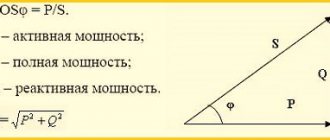
Power limiter parameters and device
The main parameters of power limiters include:
the number of controlled network phases - one or three;
Three-phase power limiter
Single phase power limiter
- maximum device-controlled current;
- maximum current through the device contacts;
- user-configurable time ranges.
Single-phase power limiter controls
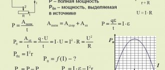
Since power limiters are digital devices, the analog signals at their inputs are converted into digital values (digitized). Analog-to-digital converters (ADCs) are designed for this purpose, converting data on the magnitude of currents and voltages into a form understandable to the device controller.
The ADCs of the voltage sensors are located inside the device, but the current sensors in some models may be located outside of it. This reduces the thermal load on the device and allows you to get rid of power contacts for connecting powerful consumers. Current sensors are non-contact (based on the principle of current transformers), while unnecessary contact connections in the controlled circuit are eliminated. An additional advantage: the device measures voltage at the entrance to the house, and current - in any circuit that is supposed to be turned off if the power in it is exceeded.
Connection diagram for a three-phase power limiter with remote current transformers
Data on measured currents and voltages enters the controller, which controls their values and calculates the missing ones: active and reactive power, direct and negative sequence currents. Its memory contains settings specified by the user. Working according to a certain algorithm, it displays the required information on the display and controls the output relay block.
To program the operation of the controller or set settings, use a block of control buttons or potentiometers. It is located on the front panel of the device and is combined with a digital indicator (display).
The device includes at least one relay with a changeover contact. Through it, either the magnetic starter or the connected load is controlled directly. Direct control is possible if the load current does not exceed the value specified in the device passport (maximum current of the contact system).
Connection diagrams for single-phase power limiters
In addition to contacts for load control, some power limiters are equipped with additional signal contacts used in alarm and automation circuits.
Power limiters, which have many additional functions, include interfaces for communication with a personal computer: RS-232 or RS-485. If you have the appropriate software, you can easily and simply set all the settings and parameters without wandering through the device menu.
Photos of power limiters
Read here! Thermal relay: purpose of the device, main characteristics + diagram with connection instructions. Review of proven manufacturers!
Connection options
It is most convenient to consider connection options using the example of the OM-310 device, for the installation of which there are several diagrams.
Scheme No. 1
This scheme provides for one load with its switching off when the power increases.
Scheme for installing a machine with one pole with all elements placed in one panel
Input cables are fed from the power lines directly into the switchboard. Three phase cables are connected to the upper contacts of the input machine, zero - to the zero bus. An example is given with a power of 15 kW for 3-phase networks, therefore the input circuit breaker is adopted with a rating of 25 A.
Each phase wire from the lower terminals is passed through the holes of the current transformers installed in the limiter. They are then connected to the required contacts in the meter.
From the meter, the phases are connected to the upper contacts of the modular contactor. The zero from the bus is connected to the meter contact. The contactor terminals must be connected via phase jumpers to the SPD, from which power is supplied to the limiter.
Scheme No. 2
The scheme implies the presence of two loads and turning off one with low priority when the power exceeds a critical value.
Connecting the limiter according to the second scheme implies the presence of two separated groups of loads
The connection is carried out by analogy with the first diagram. Load No. 1 is accepted as a non-priority load, subject to priority shutdown. The second load must be constantly on.
The non-priority load is switched off when power consumption exceeds the configured threshold. The main consumers will continue to work.
Scheme No. 3
When implementing such a scheme, both load groups are turned off. The only difference between them is the difference between the priority inserts. If the power set in the settings is exceeded, the first load is first turned off; if the power has not decreased to the required value, then load No. 2 is also turned off.
The scheme assumes the presence of two groups of loads; when the power increases, both are switched off
The first load is high power objects, such as:
- ovens;
- warm floor;
- heaters of various models and others.
After disconnecting load No. 1, the second load remains defenseless against voltage surges. The circuit contains a load relay and a functional relay.
Scheme No. 4
The fourth scheme provides for the presence of three loads, two of which are non-priority.
In such a scheme, the groups will be switched off one by one as the power increases. Load No. 1 is turned off first, followed by another. The third remains always on and unprotected by the limiter. This circuit also operates via contact from the functional relay and load relay.
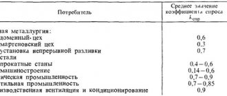
Review of manufacturers
| Model | Manufacturer | Main settings | Approximate cost, rub. |
| OM-2 | F&F Belarus | Maximum current of relay contacts: 16(3)A, AC1 Range limited power: from 200 to 2000 W Shutdown delay: 1.5 sec. Turn-on delay: 4-150 sec (adjustable) | 2070 |
| OM-14 | DIGITOP Ukraine | Power range, 0.1-14 kW Detectable voltage, V 50-400 Switch-off period at the upper limit, sec, not more than 0.02 Switch-off period at the lower limit, sec, not more than 1(120-170V) 0.02( Maximum current of relay contacts is no more than 40A | 3020 |
| OM-310 | NOVATEK Russia | Load power 2.5-30 kW Number of phases - 3 | 6900 |
| PL-11T | EKF Russia | Maximum load current - 8A Single-phase for operation with current transformer X/5A | 1570 |
| OM-630 | F&F Belarus | Power 5 - 50 or more kW step 0.5 kW possibility of setting parameters directly by the customer | 7000 |
Despite some disadvantages, power limiters are the most effective means of protecting office and household electrical appliances from network overloads.
Connection features
OM-110
To install the OM-110 power limiter, the following features can be noted:
- Install the OM-110 in its standard place (you can use it under a DIN rail).
- Connect the 220 V network, observing the correspondence between the zero and phase buses.
- Pass the load wire through a special hole - there is a current transformer there, which is a sensor of consumed electricity.
- Connect the contactor according to the diagram. OM-110 works only if there is a contactor that will switch voltage to the load.
- Set the shutdown power using the potentiometer.
- Set the operating time of OM-110 in overload mode.
- Set the time for the limiter to return to its original position after being triggered.
Connection diagram OM-110:
You can see the installation process in more detail in the video below:
How to connect a single-phase limiter
After connecting, you need to check the correct operation of the limiter. Apply power and connect a load less than the calculated one. The green LED should be lit. Then you need to connect a load that is higher than the established one. The “overload” LED should light up and after the time set by the “shutdown delay” regulator has expired, it should turn off all consumers. If necessary, the time can be adjusted. After disconnection, the return to its original state occurs automatically. The return time can also be changed using the "restart" control. Installation and configuration of the controller is completed.
OM-310
OM-310 is used at a network voltage of 380 V and a power of 3-40 kW. The installation of the power limiter of this series is no different from the previous one. The main difference is that you need to connect three phases of 380 V and a neutral wire to it. There are two indicators on the front panel that allow you to configure and monitor the operation of the device, as well as LED indicators. The setup of this device is somewhat different from the OM-110. The advantage is the ability to connect to a computer and configure it.
Installation consists of connecting all three phases and the neutral wire to the input terminals, as shown in the diagram below:
Visual installation instructions are provided in the video:
Connection OM-310
The load is connected via current transformers. Set parameters for power consumption, shutdown time during overload and recovery time after shutdown. It is mandatory to use a contactor that switches the load.
OM-630
OM-630 – three-phase power limiter. The connection occurs according to the diagram. Works only with current transformers and load relays.
- Connect the phase wires and the neutral wire.
- Connect a contactor or several as needed
- Pull the load wires through the installed holes in the device body
- Connect the power, after which the LED should light up, and after a specified time the indicator should turn yellow and the load will turn on.
The correct connection is clearly shown in the photo and diagram below:
The maximum power, shutdown time and recovery time are set using switches. All controls are located on the front panel. In addition to the above functions, the OM-630 has a trip counter function. When the limiter is triggered more than a certain number of times within an hour, the load is switched off for 10 minutes. This adjustment is also present on the front panel.
The video below clearly shows how to connect and configure the OM-630:
Review of OM-630
These devices, regardless of brand and type, protect not only the electricity supplier from overconsumption and theft, but also the consumer from overloading the home electrical network and reducing the likelihood of a fire from overheating of worn-out electrical wiring in the event of a mismatch between the network power and consumption. We hope you found our tips and instructions for connecting 110, 310 and 630 series power limiters useful.
It will be interesting to read:
- How to supply electricity to a site
- Network surge protection devices
- What is a voltage control relay
Operating principle of power limiters
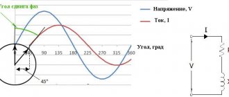
The power limiter algorithm continuously monitors the operation of the load of consumers in the electrical network. The OM measuring unit, based on current and voltage transformers, constantly scans the vectors of incoming quantities, and transmits them to the logical block to calculate the power consumption, the value of which is compared with the upper setpoint limit specified by the operator using a potentiometer. If the current values of power consumption reach a critical value, the computational logic block will issue a command to the executive circuit to operate, which will turn off the contactor. After the power limiter is triggered, you need to make sure to turn off additional electrical appliances that have exceeded the limit of electricity consumption. After a specified period of time, the OM will switch on again for further power control.
Power limiter circuit
Operating principle of the power limiter
The diagram shown in the figure shows the operation of single-phase devices.
In a three-phase network:
- the measurement circuit that monitors currents and voltages in each phase is changed;
- the process of calculating power consumption becomes more complicated.
FAQ
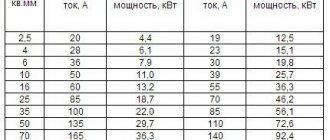
What is the maximum cross-section of wire that can be passed through the hole in the device body?
In models OM-630, OM-630-1, OM-630-2, OM-1, the hole diameter is 10 mm. Taking into account the thickness of the insulation, a wire passes with a conductor cross-section of about 32 mm2.
In OM1-3 the hole diameter is 5 mm, which corresponds to a wire with a cross-section of 6 mm2
How to choose the right current transformers for use with OM-630-2 and OM-611?
OM-630-2 and OM-611 are designed to work with a standard range of transformers with a maximum secondary circuit current of 5A.
To select a current transformer and correctly configure the power limiter, simple calculations should be carried out.
1. Determine the maximum load current based on the given power Rogr.
Imax = Rogr./230
2. Based on the maximum current, select the required transformer, while Imax.
3. Determine the power that needs to be installed on the limiter:
Rust. = Rogr./Kwhere K = Inom./5, transformation ratio of the current transformer.
Let's look at an example:
It is necessary to limit the power of Rogr. = 150kW.
— determine the max. load current:
Imax = 150000/230 = 652 A
— select one of the current transformers: 700/5 or 800/5 from the standard range of transformers.
— transformation coefficients will be: K = 700/5 = 140; K = 800/5 = 160.
— let’s determine the power that needs to be set on the limiter:
If you chose a transformer 700/5 (K=140), then Rust. = Rogr./140 = 1070 W We set the limiter to 1.1 kW.
When choosing a transformer 800/5 (K=160)
Rust. = Rogr./160 = 940 W.
We set the limiter to 940 W.
There is a choice of three power calculation options. The algorithm by which the limiter will calculate power consumption depends on this.
Phase by phase
Installed power Rust. divided by 3. If this value is exceeded in any phase, the load is switched off. For example: Rust. = 15kW. When the power value is P>Rust./3 = 15/3 = 5 kW, the load is switched off.
Total
the sum of powers in individual phases is determined, and if the Rust value is exceeded, the load is switched off (Ra+Rv+Rs>Rust.), where Ra,v,c is the power consumed in the individual phases.
For example: Rust.=15kW, Ra=10kW, Rv=6kW, Рс=0.
Р= Ra + Рв + Рс= 10 + 6 + 0=16 kW Р>Rust., the load will be turned off.
In total, with power limitation in any phase at the level of (2/5)xRust
For example: during Rust. = 15 kW the load will be turned off when the value (2/5)x15 = 6 kW is exceeded, in one of the phases or when the sum of powers in the phases exceeds 15 kW (5.5 + 5.5 + 4.0) kW.
In a three-phase network, the power calculation option is selected depending on the task at hand. For example, if an energy sales service needs to protect a weak, “sagging” electrical network and protect a transformer from overload, a *phase-by-phase* calculation is chosen.
If the network is in order, and it is necessary to “issue” electrical power to the subscriber exactly according to the paid contract, the *total* method of calculating power should be used. The summary option is suitable for consumers who are concerned about the safety of the internal electrical wiring and the section of the power line from the pole to the house.
When ordering a power limiter, follow the diagram:
Three-phase power limiters
| Name | Manufacturer | Power | Eg. nutrition | Contact |
| OM-630 | Euroautomatika | 5 -50 kW | 3x400/230+N | 2x8A |
| OM-630-1 | Euroautomatika | 5 -50 kW | 3x400/230+N | 2x8A |
| OM-630-2 | Euroautomatika | external CT | 3x400/230+N | 2x8A |
| OM-310 | Novatek | 2.5-30 kW | 130-450V | 3x63A |
*data presented as of July 2021
The maximum permissible current of built-in contacts for most devices is 8 - 16A. This is explained by the small dimensions of modern power limiters and the inability to place power relays in the product housing. To connect subscribers, external contactors designed for the required current are used. The exception is single-phase OM-1-1 and OM-14, which are capable of switching loads up to 15 kW with built-in relays.
OM-110 and OM-630 with contactors
The photo shows examples of installation of power limiters for operation in single-phase and three-phase networks, using external contactors.
Euroautomatika FiF produces the widest range of power limiting devices, both single-phase and three-phase. A separate website is dedicated to the popular OM-630, where you can find additional information and ask questions in the comments.
For configuration, it is better to connect the OM-630-1 power limiter to a computer via a USB port. All parameters are set in the Terminal program (Windows), the process is described in detail in the instructions. It is possible to specify the value and option for calculating power, the shutdown and restart delay, the operating mode of the output relay, as well as disable the controls on the front panel.
Among Novatek Electro products, the OM-310 stands out - a multifunctional device with impressive performance characteristics, rich equipment, a huge number of settings, remote control capabilities, data transfer via the MODBUS protocol and... instructions on 27 pages. In my opinion, it is the excessive complexity that prevents it from achieving the popularity of the OM-630.
Why are power limiters needed?
Energy sales organizations successfully use such devices to combat malicious defaulters, unauthorized connections and other violations of legal electricity consumption. The presence of a power limiter is often mandatory in the Technical Specifications issued to new subscribers, although the legality of such decisions is controversial and sometimes ends up in court.
How is installing a power limiter useful for the owner of a country cottage? First of all, this is a voltage and current relay in one housing. You don’t have to worry about your washing machine, microwave oven or your favorite TV. They are under reliable protection. There will be an instant shutdown in the event of sudden voltage drops or a break in the neutral wire of a three-phase network, because this device surpasses any circuit breaker in your home in terms of speed and measurement accuracy.
In conclusion, I will provide answers to frequently asked questions that the Scan Lights + technical support service encounters.
Answers to frequently asked questions
What is the maximum cross-section of wire that can be passed through the hole in the device body?
In models OM-630, OM-630-1, OM-630-2, OM-1, the hole diameter is 10 mm. Taking into account the thickness of the insulation, a wire passes with a conductor cross-section of about 32 mm2.
In OM1-3 the hole diameter is 5 mm, which corresponds to a wire with a cross-section of 6 mm2
How to choose the option for calculating the power of a three-phase limiter?
There is a choice of two power calculation options.
1. Totally , the sum of the powers in the individual phases is determined, and if the Rust value is exceeded, the load is switched off (Ra+Rv+Rs>Rust.), where Ra,v,c is the power consumed in the individual phases.
Example: Rust.=15kW, Ra=10kW, Rv=6kW, Рс=0.
Р= Ra + Рв + Рс= 10 + 6 + 0=16 kW Р>Rust., the load will be turned off.
2. In total, with power limitation in any phase at the level of (2/5)xRust.
Example: at Rust. = 15 kW the load will be turned off when the value (2/5)x15 = 6 kW is exceeded, in one of the phases or when the sum of powers in the phases exceeds 15 kW (5.5 + 5.5 + 4.0) kW.
The power calculation option is selected depending on the required task. Let’s say an energy sales service needs to protect a weak, “sagging” electrical network and protect a transformer from overload. We use *phase by phase* calculation.
If the network is in order, and it is necessary to “issue” electrical power to the subscriber exactly according to the paid contract, you should choose the *total* method of calculating power. The summary option is also suitable for consumers who are concerned about the safety of the internal electrical wiring and the section of the power line from the pole to the house.
What should you do if you need to protect your power limiter from unauthorized access and changing settings?
Power limiters do not have any locks that prevent end users from changing settings. We offer the following options:
1. Use the OM-630-1 power limiter, which has the regulators on the front panel turned off by software.
2. Use a shield with a sealing panel that prevents access to potentiometers and power limiter switches.
3. Install the shield at a sufficient height from the ground, or other places with limited access.
The lineup
The table shows the main characteristics of devices produced* by Russian and foreign (St. Petersburg), "Meander" (St. Petersburg), "Euroavtomatika FiF" (Lida, Republic of Belarus)
Name Manufacturer Power Eg. power supply Contact OM-1 Euroautomatic 3-30 kW 50-260V 2x8A OM-1-1 Euroautomatic 1 -16 kW 50-450V 75A OM-1-3 Euroautomatic 1-10 kW 230V 16A OM-3 Euroautomatic 0.5-5 kW 230V 16A OM-611 Euroautomatika external CT 230V 10A OM-63 Meander 1-14 kW 50-400V 8A OM-110 Novatek 0-20 kV 130-300V 8A
Three-phase power limiters
Name Manufacturer Power Eg. power supply Contact OM-630 Euroautomatic 5 -50 kW 3x400/230+N 2x8A OM-630-1 Euroautomatic up to 50 kW 3x400/230+N 2x8A OM-630-2 Euroautomatic external CT 3x400/230+N 2x8A OM-310 Novatek 2 ,5-30 kW 180-450V 2x8A
Data presented as of May 2021.
Please note that the maximum allowable contact current is 8 - 16A. This is explained by the small dimensions of modern power limiters and the inability to place power relays in the device housing
To connect subscribers, external contactors designed for the required current are used. The exception is OM-1-1, capable of switching loads up to 16 kVA with a built-in relay.
The photo below shows examples of installation of power limiters for operation in single-phase and three-phase networks, using external contactors.
Euroavtomatika FiF produces a wide range of power limiting devices, both single-phase and three-phase. The best-selling of them is OM-630, detailed information about which can be read on the thematic website www.om-630.ru
A special feature of OM-630-1 is the ability to configure using a personal computer. All parameters: power value and calculation option, shutdown and restart delay, output relay operating mode, are set programmatically when connected to a computer via a USB port.
Among Novatek Electro products, the OM-310 stands out - a multifunctional device with impressive performance characteristics, rich equipment, a huge number of settings, remote control capabilities, data transfer via the MODBUS protocol and... instructions on 27 pages. In my opinion, it is the excessive complexity that prevents it from achieving the popularity of the OM-630.
Advantages and disadvantages
In addition to the ability to turn off excess power, the power limiter has a number of additional characteristics. They are unique and very useful. It helps not only to ensure that power is not exceeded, but also to increase the security of the power grid and monitor the safety of the equipment in use.
The advantages include the presence of the following technical characteristics of limiters:
It monitors not only the active part of the power provided by conventional electric heaters and other active consumers. It also monitors the reactive component of consumption provided by electric motors. Reactive power cannot be tracked by other devices.
The performance of this device is independent of ambient temperature and operates with equal accuracy over a wide temperature range. In contrast, a circuit breaker may not operate for a long time at low temperatures, thereby creating dangerous overvoltages in the network.
This device has color indication. In the simplest devices, one LED indicates the presence of excess load; in more advanced devices, the current power consumption is indicated on a digital display, which provides current information about the load in the network and other parameters.
When a given level of electricity consumption is exceeded, the consumer is not switched off instantly, but according to a certain delay, which is set manually. This allows you to skip short peak loads and prevent the network from working with large, long-term loads. For example, by setting the desired time, you can give a powerful electric kettle time to boil water, but prevent longer loads.
On it you can set the consumption value at which it will trigger. To set new load values, you do not need to purchase new devices. Thanks to this, you can monitor the absence of electricity theft.
This device turns on the load automatically after a specified time. This time is set manually on the device. A so-called automatic restart is performed. Thanks to this, there is no need to open the electrical panel every time it is triggered. This is very convenient not only for consumers, but also for supply organizations. They can restrict access to the electrical panel, since the electricity will turn on automatically after a certain time.
The limiter does not perform the functions of disconnecting the network. It measures the current flowing through the power line and provides control signals to the starters that control the system. Therefore, there is no need to create additional breaks in the network.
Consumption limiters can perform the function of protecting three-phase electric motors during phase breaks; they can monitor current imbalance and respond to it. An additional function is protection against low-quality voltage. In this case, it controls the supply voltage of all three phases. The device can perform the function of a residual current device (RCD). At the same time, it controls the currents leaving the system to the ground.
The disadvantages of this device include, first of all, its high cost. It is significantly more expensive than an ordinary machine gun. The limiter itself cannot switch off and on loads with high currents. Magnetic starters or contactors must be installed together with it.
The limiter supplies a small current to the control coils of the starter and it turns the power line on or off. The cost of electrical installation work is additionally increased by the cost of this equipment. In addition, it is necessary to regularly monitor the serviceability of starting devices, since they have moving parts.
Finally, it is worth noting that these devices require additional space in the electrical panel. For these reasons, consumers rarely install such equipment of their own free will. In most cases, it is installed at the request of electricity suppliers in accordance with agreed connection projects.
A power limiter or PZR may not be installed
Evgeniya:
06/04/2016 at 00:31
This is what the network company responded. What can you comment?
Eastern Electric Networks, a branch of PJSC Moscow United Electric Grid Company, has considered your request dated 06/01/2016. No. LK-16-216003, received in the Personal Account registered on the Portal for Technological Connections, and reports the following. In accordance with Art. 38 of the Federal Law of March 26. 2003 No. 35-FZ “On Electric Power Industry” (hereinafter referred to as 35-FZ) - in order to prevent rolling blackouts, an organization providing services for the transmission of electrical energy to its consumers is obliged to ensure the possibility of individual limitation of the mode, both its own consumption and the consumption of served consumers electrical energy. In this connection, you, on the basis of clause 11.1 of technical conditions No. I-16-00-939053/102/B8 and in accordance with clause 25.1 “c” of the Rules for the technological connection of power receiving devices of electrical energy consumers, electrical energy production facilities, as well as electrical grid facilities belonging to grid organizations and other persons, to electrical networks, approved. RF PP dated December 27, 2004 No. 861 (hereinafter referred to as the TP Rules), it is necessary to carry out work on the installation of the receiving device, including metering devices and protection devices that provide control of the maximum power value. In addition, Art. 38 Federal Law No. 35 prohibits restricting the consumption of electrical energy in relation to consumers who do not have payment arrears. We inform you that the network organization has no intention of limiting your power consumption in the absence of payment arrears, but at the same time, the maximum power of your power receiving devices should not exceed the permitted one, i.e. 15 kW. Thus, you need to install a device that provides control of the maximum power value, which is a technical solution for protecting networks from overload and preventing unauthorized consumption of electricity in excess of the power limits set for the consumer, bypassing metering devices. Devices that provide control of the maximum power value can be elements of the electrical circuit, including electrical appliances, devices, elements of automated electrical energy metering systems, the function (or one of the functions) of which is to control the maximum power value. The purpose of the device must be indicated in the manufacturer's passport (operation manual). You can use certified protective devices programmed at the factory for a power of 15 kW, or install a multifunctional electricity meter with a load control function, which is programmed by Energouchet specialists in their area of responsibility. If such a meter is installed, a circuit breaker will be sufficient. These measures are carried out by the applicant independently on the basis of clause 16.3. Rules for the technological connection of power receiving devices of electrical energy consumers, electrical energy production facilities, as well as electrical grid facilities belonging to network organizations and other persons to electrical networks, approved. by Decree of the Government of the Russian Federation dated December 27, 2004 No. 861 - the applicant fulfills obligations for technological connection within the boundaries of the site on which the applicant’s connected power receiving devices are located; the network organization fulfills these obligations up to the boundaries of the site on which the applicant’s connected power receiving devices are located. We also inform you that when carrying out measures for technological connection provided for in clause 11 of the Technical Conditions, you can be guided by the Standard design solutions for organizing electrical energy metering at applicants’ facilities when carrying out technological connection to the electrical networks of PJSC “MOESK”, which also contains requirements for metering devices and installation. This document was developed and approved by PJSC “MOESK” on the basis of current legislation and is available for review on the website (moesk.ru) in the “information for clients” section. After completing the technological connection measures, you need to notify the network organization about this fact. We inform you that the network organization provides additional services on a reimbursable basis to perform work on the part of the applicant. You can obtain detailed information about the provision of additional services, as well as familiarize yourself with the Price List, on the official website in the “Additional Services” section or by contacting specialists in the additional services development sector of the Eastern Electric Networks branch of PJSC “MOESK” by phone: 8(496) 516-72-93, 967-178-30-71.
Responsible manager: A.E. Novichikhin, Head of the Wind Farm Customer Service Department Single contact: 8-800-700-40-70 (24-hour single help line on issues of technological connection and power outages)