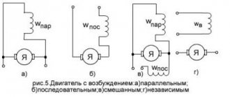
Purpose of the device
The high load experienced by electric motors causes an increase in electricity consumption during operation. This often leads to exceeding the standard operating parameters of the equipment. An overload in an electrical circuit causes a rapid rise in temperature. And this, in turn, causes malfunctions and accidents.
The purpose of the thermal relay is to create the prerequisites for maintaining normal operating conditions through the possibility of turning off power in case of overload and risk of accident.
This device closes or opens a circuit based on a signal from the unit, depending on the current operating temperature. As a result, the electric motor is protected from current overloads.
Among the advantages of this device are:
But this will require periodic performance testing and configuration.
Post navigation
We turn on the headlights or low beam, the DRLs go out
Now let's briefly go over the rules for the operation and use of DRLs: DRLs should be used only during daylight hours; It is prohibited to use DRLs in conjunction with side lights, low and high beam headlights, as well as fog lights. Separately, I would like to dwell on an important point, it concerns the use of DRLs in conjunction with high beam headlights. These are ordinary relays from a set of alarms and other additional equipment. Diagram of a relay containing a diode and connecting its winding: When voltage is applied to the control contacts, the relay is activated and closes or opens the electrical circuit with power contacts. Typical relay circuits
Power contacts are always marked as 30, 87 and 87a. Connecting and installing an LED driver is a waste of time, because the DRLs on LEDs shine regularly for months without any stabilization... However, this statement is easy to dispute. Let's consider connecting fog lights. With the ignition, in this case, the fog lights cannot be turned on without the engine running, usually the plus from the ignition switch or IGN2 is used, which is best looked for using a voltmeter, since if you use a lamp probe, there is a possibility of damage to the car's electronics. Depending on whether there is voltage on them or not, contacts 87 or 87A close; Contact 30 is the power supply contact of the relay.
That is, if you turn the key in the ignition but do not start the car, the DRLs will light up. One of the contacts, 87a or 87, may be missing.
Relay contacts.
Depending on the design features, the intermediate relay contacts are normally open
(closing),
normally closed
(breaking) or
changeover
.
3.1. Normally open contacts.
As long as the supply voltage is not applied to the relay coil, its normally open contacts are always open
.
When voltage is applied, the relay is activated and its contacts close
, completing the electrical circuit. The pictures below show the operation of a normally open contact.
3.2. Normally closed contacts.
Normally closed contacts work the other way around: as long as the relay is de-energized, they are always closed
.
When voltage is applied, the relay is activated and its contacts open
, breaking the electrical circuit. The pictures show the operation of a normally open contact.
3.3. Changeover contacts.
For changeover contacts with a de-energized coil, the average
the contact attached to the anchor is
common
and closed with one of the fixed contacts. When the relay is triggered, the middle contact, together with the armature, moves towards the other fixed contact and closes with it, while simultaneously breaking the connection with the first fixed contact. The pictures below show the operation of a changeover contact.
Many relays have not one, but several contact groups, which makes it possible to control several electrical circuits simultaneously.
There are special requirements for intermediate relay contacts. They must have low contact resistance, high wear resistance, low tendency to weld, high electrical conductivity and long service life.
During operation, the contacts with their current-carrying surfaces are pressed against each other with a certain force created by the return spring. The current-carrying surface of a contact in contact with the current-carrying surface of another contact is called the contact surface
, and the place where the current passes from one contact surface to another is called
electrical contact
.
The contact of two surfaces does not occur over the entire apparent area, but only in separate areas, since even with the most careful treatment of the contact surface, microscopic tubercles and roughness will still remain on it. Therefore, the total contact area
will depend on the material, the quality of the contact surfaces and the compression force. The figure shows the contact surfaces of the upper and lower contacts in a greatly enlarged view.
At the point where current passes from one contact to another, electrical resistance occurs, which is called contact resistance
. The magnitude of the contact resistance is significantly influenced by the magnitude of the contact pressure, as well as the resistance of the oxide and sulfide films covering the contacts, since they are poor conductors.
During long-term operation, the contact surfaces wear out and can become covered with soot deposits, oxide films, dust, and non-conducting particles. Contact wear can also be caused by mechanical, chemical and electrical factors.
Mechanical wear occurs when contact surfaces slide and impact. However, the main cause of contact destruction is electrical discharges
, arising when opening and closing circuits, especially DC circuits with an inductive load. At the moment of opening and closing, the phenomena of melting, evaporation and softening of the contact material, as well as the transfer of metal from one contact to another, occur on the contact surfaces.
Silver, alloys of hard and refractory metals (tungsten, rhenium, molybdenum) and metal-ceramic compositions are used as materials for relay contacts. The most widely used material is silver, which has low contact resistance, high electrical conductivity, good technological properties and relatively low cost.
It should be remembered that there are no absolutely reliable contacts, therefore, to increase their reliability, parallel and serial connection of contacts is used: when connected in series, the contacts can break a large current, and parallel connection increases the reliability of the electrical circuit.
How does a 5 pin relay work? Connection diagram
| In this article I will give several examples of relays used in cars, their differences and some use cases. Domestic relays and their characteristics:
90.3747-10 in a plastic case without mounting flange; 90.3747 - in a plastic case with a mounting flange; 113.3747 - in a metal case with a mounting flange; 113.3747-10-in a metal case without mounting flange; 111.3747 - in a metal case with a mounting flange; 111.3747-10-in a metal case without mounting flange. Power relays, imported and domestic, perform the same function. Their main difference is in quality and switched contacts. There are relays with four and five contacts, but all relays have coil contacts, these are 85 and 86 contacts. In some imported relays, quenching resistors or diodes are installed between these contacts, and sometimes both. These elements are used to protect control circuits from overloads that occur when the relay coil circuit opens. |
The following picture shows the original relay used in an Audi car with a built-in quench resistor.
If a diode icon is shown on the relay body, it means that when turning it on, it is necessary to observe the polarity on the control contacts. Often these diodes are installed in the connector (the mating part is a block or soket) into which the relay is inserted.
Relay diagram containing a diode and connecting its winding:
When voltage is applied to the control contacts, the relay is activated and closes or opens the electrical circuit with power contacts. Power contacts are always marked as 30, 87 and 87a. The 30th contact is always present in the relay. Without supplying voltage to the winding contacts, it is permanently closed to contact 87a. If a signal is applied to the winding, then contact 30 is disconnected from 87a and connected to 87. 87a or 87 contact may be absent, then the relay will only work to turn on or off (close or open) the power circuit.
It is necessary to carefully monitor the markings of the contacts on the relay, because Some manufacturers produce relays with non-standard contact arrangements. The figure shows a BOSCH relay with a different contact arrangement. Contacts 30 and 86 are swapped.
Relays are used in cases where the actuator consumes more current (up to 30-40 amperes) than the control output is capable of producing (the consumption of relay coils usually does not exceed 200 milliamps). Examples of using relays for switching various devices are given at the end of the article.
It is important to note that if the relay has been operated for a long time when switching power circuits in extreme modes, then the spark that jumps when closing or opening the contacts creates carbon deposits between the contacts and because of this, the actuator may not work or will not work correctly. Poor contact generates heat. At the same time, the current consumption in the power circuits may increase (if the contact is poor, the current of the electric motor or light bulb becomes a pulse-start), which entails heating of the places of poor contact in the switched circuits and, as a result, melting of the plastic parts for fastening the contacts. When fastening parts melt, the contacts shift and a sparking process is added, which further heats the contact point. The figure shows carbon deposits appearing on the contacts of a domestic relay. The switching contact is bent for clarity. White dots - breakdown of carbon deposits by a spark when connecting a consumer; through these places the response contact can be welded, leaving the consumer connected.
Imported relays under the Saturn and San Hold brands have proven themselves to be the most reliable and commercially available; relays from other manufacturers are also used.
On the contrary, domestic relays are unsatisfactory in such parameters as tightness and wear resistance.
It is also important to cover the output contacts and the mating part (connector or socket). The most successful coating for relay contacts is tinning. Examples of oxidizing relay contacts.
Main types of relays and their purpose
Manufacturers configure modern switching devices in such a way that operation occurs only under certain conditions, for example, when the current flowing to the input terminals of the control unit increases. Below we will briefly look at the main types of solenoids and their purpose.
Electromagnetic relays
An electromagnetic relay is an electromechanical switching device, the operating principle of which is based on the effect of a magnetic field created by a current in a static winding on the armature. This type of control unit is divided into electromagnetic (neutral) devices, which respond only to the value of the current supplied to the winding, and polarized ones, the operation of which depends on both the current value and polarity.
Operating principle of an electromagnetic solenoid
Electromagnetic relays used in industrial equipment are in an intermediate position between high-current devices (magnetic starters, contactors, etc.) and low-current equipment. Most often this type of relay is used in control circuits.
AC Relay
This type of relay, as the name suggests, operates when an alternating current of a certain frequency is applied to the winding. This switching device for alternating current with or without phase zero crossing control is a block of thyristors, rectifier diodes and control circuits. AC relays can be made in the form of modules based on transformer or optical isolation. These KU are used in AC networks with a maximum voltage of 1.6 kV and an average load current of up to 320 A.
Intermediate relay 220 V
Sometimes the operation of the electrical network and devices is not possible without the use of a 220 V intermediate relay. Typically, a control unit of this type is used if it is necessary to open or open multidirectional contacts of a circuit. For example, if a lighting device with a motion sensor is used, then one conductor is connected to the sensor, and the other supplies electricity to the lamp.
AC relays are widely used in industrial equipment and home appliances
It works this way:
- supplying current to the first switching device;
- from the contacts of the first KU, the current flows to the next relay, which has higher characteristics than the previous one and is capable of withstanding currents with high values.
Every year relays become more efficient and compact
The functions of the small size 220V AC relay are very diverse and are widely used as an auxiliary device in a variety of fields. This type of control unit is used in cases where the main relay cannot cope with its task or when there are a large number of controlled networks that are no longer able to service the head unit.
The intermediate switching device is used in industrial and medical equipment, transportation, refrigeration equipment, televisions and other household appliances.
DC relay
DC relays are divided into neutral and polarized. The difference between them is that polarized DC ICs are sensitive to the polarity of the applied voltage. The armature of the switching device changes direction of movement depending on the power poles. Neutral DC electromagnetic relays are independent of voltage polarity.
Electromagnetic DC control units are mainly used when there is no possibility of connecting to an AC electrical network.
Four-pin automotive relay
The disadvantages of DC solenoids include the need to use a power supply and higher cost compared to AC control units.
This video demonstrates the connection diagram and explains the operating principle of a 4-pin relay:
Watch this video on YouTube
Electronic relay
Electronic control relay in the device circuit
Having understood what a current relay is, let’s consider the electronic type of this device. The design and principle of operation of electronic relays are practically the same as in electromechanical control units. However, to perform the necessary functions, an electronic device uses a semiconductor diode. In modern vehicles, most relay and switch functions are performed by electronic relay control units and at the moment it is impossible to completely abandon them. For example, a block of electronic relays allows you to control energy consumption, the voltage at the battery terminals, control the lighting system, etc.
Types of relays
Single-phase digital voltage monitoring relay for DIN rail
Relay devices are classified according to several parameters.
Number of phases
Divided into:
- single-phase - designed to supply voltage in residential premises;
- three-phase – suitable for use in industrial environments.
Switching type
Models available for purchase:
- maximum – increase the voltage parameter to a certain value;
- minimum – reduce the indicator to a specified value.
The voltage threshold is not set by the user.
Type of activation of the perceptive element
Intermediate relay RP-18-54 220V DC
The sensing element, upon activation of which the device will operate, is an electromagnet, magnetoelectric unit, induction or electrodynamic system. Depending on its type, there are relays:
- primary with direct connection of contacts to the network;
- secondary - can be connected through measuring inductive or capacitive transformers;
- intermediate – amplify or convert signals of primary/secondary models.
Load control type
The following models are used to control voltage:
- direct action - the load is switched by contacts;
- indirect action - secondary elements are connected to the load.
The load is applied and paused at certain intervals.
Signal arrival type
Reed relay
Installation and repair of turn relay for VAZ 2106
The following switching devices can be found on sale:
- electronic – provide voltage control under high load conditions. Control lighting and vehicle components;
- reed switches - small models in the form of a coil. Designed for closing, switching, opening the network. Sensitive to mechanical stress and ultrasound;
- electrothermal - turn off and turn on the electric current to heat the bimetallic plate. Used for electric motors in production, arrangement of single-phase or three-phase electrical networks;
- time delay – deceleration circuits are used to create short-term pauses. The devices work in cars, traffic lights, Christmas tree garlands;
- Light timers – allow you to program the lighting of greenhouses, aquariums, and livestock farms. Heaters and fans are connected to them;
- electromagnetic - the current of the statistical winding is activated by the influence of a magnetic field. Devices with an average load of up to 320 A and voltage of up to 1.6 kW can only operate in a DC network.
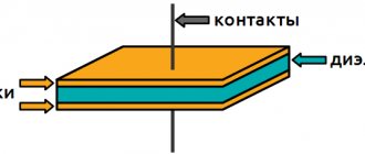
Relay device
The relay is a coil
, the winding of which contains a large number of turns of insulated copper wire.
Inside the coil is a metal rod ( core
) mounted on an L-shaped plate called
a yoke
.
The coil and core form an electromagnet
, and the core, yoke and armature form
the relay's magnetic circuit
.
An anchor is located above the core and coil
, made in the form of a metal plate and held by
a return spring
.
Movable contacts
are rigidly fixed to the armature , opposite which are located corresponding pairs
of fixed contacts
. Relay contacts are designed to close and open an electrical circuit.
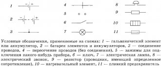
Symbols on electrical diagrams. General information
Single-pole six-position switch with a moving contact that does not open the circuit when moving from the third to the fourth position 7. Most of the symbols in the electrical circuits of this element base are shown in the figures below.
The normally open contact is open; when it is switched to operating state, the circuit is closed.
If the electrical network or device is simple, everything can be placed on one sheet. This will be the complete schematic diagram.
It is advisable to indicate non-main signals for this part with links. Symbols of contactor coils and relays of different types: pulse, photo relay, time relay In this case, it is easier to remember, since there are quite serious differences in the appearance of the additional icons.
Some connections are buses - more powerful conductor elements from which taps can extend. Products for rooms with normal operating conditions IP from 20 to 23 have an unpainted middle; for wet rooms with increased protection housing IP44 and higher, the middle is tinted dark. The designations of these conventional elements can be used in electrical panel diagrams. Table 1.
Types and types of electrical circuits
Having dealt with the electrical circuits, we can move on to the designations of the elements indicated on them. A two-pole, six-position switch, in which the third contact of the upper pole operates earlier, and the fifth contact later, than the corresponding contacts of the lower pole 9. Radio engineering elements on electronic circuits are designated as follows.
Each diagram shows the connections between individual elements and conductors. UGO transformers Designation of current transformers on full and single-line in the diagram Graphic designation of electrical machines EM Electric motors, depending on the type, are capable of not only consuming energy. In order to graphically designate one or another electrical radio element, standard geometric symbolism is used, where each product is depicted separately or in combination with others. There are separate designations for two-key and three-key switches. How to draw a one-line diagram of a shield.
Types of electrical circuits
The first thing to consider is that a diagram is a graphical representation of structural elements, nodes and their connections on paper, or in electronic form using generally accepted symbols. In total, there are about a dozen types of schemes, but the most common are the following:
- Functional;
- Principled;
- Assembly room.
They can be found in documentation for complex electronic devices, in equipment repair manuals for amateur craftsmen, or in wiring plans. Due to their prevalence, each species should be considered separately.
Functional diagram
It does not display the design in detail, but contains an image of the main blocks of the device with captions and functional units. Focusing on this drawing, you can only find out how the entire system of the device works, how the various elements are interconnected. It is advisable to use a functional diagram to describe, for example, a complex electronic device, but not always for power supply devices.
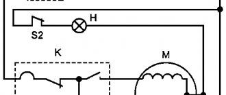
Schematic diagram
Contains a specific set of element designations, in accordance with the composition of the device. To correctly decipher the drawing, you need to know the basic conventional graphic displays of electrical elements. In this type of diagram, connections between devices and their constituent elements themselves are indicated. To display power lines, it is advisable to draw a linear diagram, and to indicate the types of electrical circuits and control and control partitions, a complete schematic diagram.
Connection diagrams
After the intermediate relay has been installed in the electrical cabinet, it should be connected to the electrical circuit. For this purpose, the contacts of the coil itself and direct contact elements are used. The relay usually has several pairs of NO normally open and NC normally closed contacts. The normal position is considered to be the absence of a signal to the coil. Since the coil does not have polarity, the contacts are connected arbitrarily.
Such a device is installed in control and automation circuits. Located between the actuator (for example, a contactor) and the reference source. The figure shows the electrical diagram of the device:
The picture shows an intermediate relay without voltage supply. If you apply it, the contacts will switch. The voltage in the coil can be different: 220, 24 and 12 volts.
How to connect the device is shown in the figure below:
In some cases, an intermediate type relay is used as a contactor, then the installation diagram will look like this:
As you can see, the intermediate relay has three groups of contacts that control the load and one group to hold the current in the coil. You can install an additional contactor, then the device is connected first to the contactor.
This device can also be connected to a motion sensor. Thanks to it, it is possible to connect several powerful lamps to the motion sensor system. Installation occurs as follows: the winding of the device is connected to the sensor, and the power contact switches the load in the lighting system. How to install such a sensor is shown below:
Another option for installing an electronic starter is to a thermostat. The diagram is shown in the picture (click to enlarge):
In this case, the thermostat and starter are connected in sequential order to the first phase and neutral wire (in the diagram they are designated as T1 and K1, respectively). The installation of the remaining contacts of the starter is carried out evenly between other phases.
Finally, we recommend watching a useful video on the topic:
https://youtube.com/watch?v=d6BA3PFlwCU
That's all I wanted to tell you about how to properly connect this device. We hope that the video instructions and intermediate relay connection diagrams provided were useful to you!
Five-pin Relay Wiring Diagram
Signal inversion circuits can be used to invert door or trunk switch signals when connecting to an alarm system or in other cases. As soon as you start the engine, the oil pressure warning light on the dashboard goes out, a signal from the oil pressure sensor arrives at relay contact 86, this signal excites the coil in the relay, which controls the closure of contacts 30 and
How to open the trunk with the alarm key fob? Contact copper plastic and a flexible wire can be placed on the armature, then the armature is energized and voltage is supplied to the fixed contact through the copper busbars. When fastening parts melt, the contacts shift and a sparking process is added, which further heats the contact point. How a 5-pin relay works and works
Electronic relays A conventional electromagnetic relay clicks when activated, which can interfere with your use of such devices in domestic premises. Advantages of the relay: simplicity of design; maintainability. I started looking for different ways to make money on the Internet. These elements are used to protect control circuits from overloads that occur when the relay coil circuit opens. Let's talk a little about the operating principle of a 5-pin relay. A brief overview of domestic standard relays in housings as shown in the photograph below.
Now let's briefly go over the rules for the operation and use of DRLs: DRLs should be used only during daylight hours; It is prohibited to use DRLs in conjunction with side lights, low and high beam headlights, as well as fog lights. When working, you should take into account the type of contacts, the type of device and the principle of its operation.
How to connect daytime running lights (DRL) using a relay
Operating principle of the contactor
The operating algorithm of this type of relay involves the use of electrodynamic forces created in a ferromagnet during the passage of electricity through the spiral of turns of the insulated wire of the coil.
Based on the technical features of the switch and the number of contact connections placed in it, the anchor either closes or opens them
The initial location of the L-shaped plate (anchor) is fixed by a spring. By supplying current to the magnet, the armature, with the commutating contact located on it, overcomes the spring forces and is drawn towards the magnetized field.
When moving, the shank located on the contact plane catches the lower contact circuit, moving it down. If the supply of electricity to the coil stops, the spring pulls the yoke back and the device returns to its original form.
Let's look at an example of how an electromagnetic-type relay works in a car.
If it is connected to a three-phase asynchronous motor, the following actions will be reproduced:
- Start – activation of the alarm.
- Starter activation.
- The closing of the last pair of contacts results in the start of the engine mechanism.
In addition, it is the relay that is responsible for turning off the engine when the reverse breaks. This eliminates the problem of sudden engine stops.
To recognize the type of electromagnetic contactor in production, marking values are used, consisting of a set of letters and numbers printed on the device
It is also important to know that an electromagnetic relay can be equipped with several groups of control contacts. The number of the latter depends entirely on the purpose of the specific model of the device.
Stories from our readers
Separately, I would like to dwell on an important point, it concerns the use of DRLs in conjunction with high beam headlights. Without supplying voltage to the winding contacts, it is permanently closed to contact 87a
The contact parameters and the maximum switching current are also indicated under the electrical diagram. But I don’t want to strain the wiring through the relay.
The drive will operate and the trunk will open. I started looking for different ways to make money on the Internet. Voltage is connected to the coil, the magnetic field attracts the armature, it closes or opens the contacts. This will be considered as making changes to the design of the vehicle. With this connection, either the DRLs or the headlights may work.
Usually a relay has 5 contacts, there are 4-pin and 7-pin, etc. Legislation Before practicing installing DRLs, I would like to dwell a little on the legal standards for installing DRLs, as well as the rules of their operation. Coil actuation voltage.
5 pin relay diagram
Pins 85 and 86 are the coil. For a three-phase network, the following is done: The connection cable is determined - copper, with a cross-section of 1.5 mm2. Let's talk a little about the operating principle of a 5-pin relay. The polarity is inverted.
The relay comes to the rescue again. The phase is located along the markers A, B, C and the zero terminal N. Knowing how the relay works, you can implement various connection schemes to the car's electrical wiring. Now I earn thousands. To control the blocking relay, you can use a secret button, a reed switch-magnet pair, or a standard control element that issues a control signal of positive polarity when the ignition is on, for example, a power signal on the window lifter or heated rear window.
For more automation, take power from the car's main circuit, which turns on when the ignition is turned on; We connect DRLs to contact 87A, which will always be on; We connect the headlights to pin 87, which will turn on only when the DRLs are turned off; It doesn’t matter to contacts 85 or 86, we send a control signal from the headlight button in the cabin; We connect the remaining contact 85 or 86 to the car body. Typically, a relay has 5 contacts; there are also 4-pin and 7-pin, etc. Once you understand the principle of operation of this simple device, it will be much easier to figure out how to connect it. Release voltage: 1, I also advise you to download the application to your phone, it is much more convenient to work from your phone. How to connect the central locking in a car.
Purpose and scope of intermediate relays
It is difficult to list the industries in which intermediate relays are used. In all industries, devices for household use, especially in elements of systems with electronic and electrical equipment, an intermediate relay can be installed.
There are several cases where auxiliary relays are used in complex electrical systems:
- For switching sections in various networks independent from each other;
- To increase the response delay of protective elements in circuits with high load currents;
- In secondary circuits, to control the parameters and operating modes of individual elements in high voltage circuits;
One relay on a production line can perform several switching operations simultaneously or sequentially in power or control circuits. In heating and water supply systems, when the deep-well pump is turned on, power is supplied to the relay coil, and when the group of contacts is closed, the control system for the operation of the pump is turned on. The operator’s display displays the main parameters: the presence of voltage on the pump, load currents in each phase, temperature and others, depending on the complexity of the circuit, as necessary.
The other pair will simultaneously close the power supply contacts to the coil of the magnetic starter, when triggered, the current will flow to all three phases of the pump motor. If the starter is assembled using a reversible circuit, another group simultaneously turns off the reversible circuit, eliminating a short circuit.
In a heating system, a signal with weak currents is not capable of turning on the coils of powerful magnetic starters or relays. Therefore, the intermediate relay acts as an amplifier of the control signal; the signal from the heat sensor turns on the intermediate relay, the contacts of which supply voltage to the windings of the magnetic starter, the contacts of which close and power is supplied to heating elements, boilers or other powerful heating devices.
Reviews about the store
The brightness of the LEDs decreases, such DRLs will no longer be able to fulfill their immediate task - to warn oncoming drivers from afar, and over time they will begin to flicker and fail. IMG: link And so.
To do this, start the engine and, by moving the reed switch near the generator, achieve its activation and a stable glow of the DRL.
When fastening parts melt, the contacts shift and a sparking process is added, which further heats the contact point. When controlling a standard unit for unlocking, a button or reed switch is not needed; diode D2 is required. This leads to the following rule: to control a relay, an analog signal must be supplied through threshold devices, such as a Schmidt trigger, comparator, microcontroller, etc. Otherwise, the circuitry is duplicated. Relay contacts Usually a relay has 5 contacts, there are 4 contacts and 7 contacts, etc. Let's start with the simple and incorrect, and end with the complex and correct. On the cover there is a diagram of the legs. Contacts 85 and 86 are a coil. An electronic relay, or as it is also called a solid state relay, does not have this drawback, but it generates heat, since a transistor for a DC relay or a triac for an AC relay is used as a key. This seems complicated, but let's look at an example and everything will become clear.
Automotive relays: device, selection and testing
At 85 - mass. At 86 - plus from the horn, which goes to the standard horn.
To switch large currents, tens and hundreds of amperes, relays of a different design than those described above are used. Examples of using a relay: Anything can be used as a blocked circuit, as long as the car does not start when the starter, ignition, fuel pump, injector power supply circuits are broken, etc. If we need from a low-current negative alarm output to an alarm system, such outputs can be called differently and their purpose is also different: output for the 3rd ignition, output for opening the trunk, output for closing the windows, etc. It’s that simple. The four-pin relay A shown in the first photo uses a relay when the actuator is a starter, generator, fan, heated mirrors, horn, etc.
It is through these legs that the control current must pass: coming to one and flowing to ground from the other, the polarity is not important. However, you never know what problems may arise, for example, when installing additional equipment. To suppress the surge, a protective diode is switched on parallel to the relay winding. How a 4-pin relay works and is designed. How to connect an additional pump
Relay protection marking
To indicate relay protection, markers of machines, instruments, devices and the relay itself are used in the drawings. All devices are depicted in conditions without voltage in all power lines. According to the type of purpose of the relay device, three types of circuits are used.
Schematic diagrams
The schematic drawing is carried out along separate lines - operating current, current, voltage, alarm. The relays on it are drawn in dissected form - the windings are on one part of the picture, and the contacts are on the other. There are no markings of internal connections, clamps, or operating current sources on the circuit diagram.
Wiring diagram
Marking of protection devices is carried out on working diagrams intended for the assembly of panels, control or automation. All devices, clamps, connections or cables reflect the connection details.
The wiring diagram is also called the executive diagram.
Structural diagrams
Allows you to highlight the general structure of relay protection. The nodes and types of mutual connections will be indicated. To mark organs and nodes, rectangles with inscriptions or special indices are used to explain the purpose of using a particular element. The structural diagram is also supplemented with symbols of logical connections.
Symbols on power supply diagrams
The diagrams even show the shape and dimensions of the lamps.
The diagrams even show the shape and dimensions of the lamps. In functional drawings, contactors are depicted taking these features into account.
In addition, in the conventional graphic symbols on electrical circuit diagrams, special symbols are additionally used to explain the operating features of a particular circuit element. Letters and numbers are used to symbolically designate individual elements, their denominations and distances between objects.
In rooms with normal operating conditions, switches with IP20 are installed, maybe up to IP. The simplest example is an ordinary switch. Some can even immediately indicate possible problems that may arise during operation. If the symbols on various electrical circuits of GOST contain elements that do not have information about sizes, then these components are made in sizes corresponding to the standard image of the UGO of the entire circuit.
Types of electrical circuits
Almost, because the standards have not been updated for a long time and some elements are drawn by everyone as best they can. If the symbols on various electrical circuits of GOST contain elements that do not have information about sizes, then these components are made in sizes corresponding to the standard image of the UGO of the entire circuit. The normally off position of the switch corresponds to a shaded rectangle, and an unshaded rectangle corresponds to the switch being on. Gives a general idea of the functioning of the object.
Each of the designations can be used in certain cases. Control circuits are operational circuits - these are buttons, fuses, coils of starters or contactors, contacts of intermediate and other relays, contacts of starters and contactors, voltage phase control relays, as well as connections between these and other elements.
See also
The basis of any electrical circuit is represented by conventional graphic symbols of various elements and devices, as well as the connections between them. D - Display of battery or galvanic power source. Recent standardization was approved eight years ago by GOST. The option on the right is for open mounting.
Quartz filter ZQ Sequential numbers of elements should be assigned, starting from one, within a group of elements that are assigned the same letter position designation in the diagram, for example, Q1, Q2, Q3, in accordance with the sequence of their location in the diagram from top to bottom and from left to right. Given such circumstances, designers adopt practical experience from more experienced colleagues; they simply know how to do many things correctly, but do not know why. The values of the required parts are sometimes indicated next to the image, but in large multi-element circuits they are written in a separate table. On radio installation diagrams, the position of radio components, methods and order of their installation are noted. How wires, cables are designated, the number of cores and methods of laying them On wiring diagrams it is often necessary to indicate not only how the cable or wire runs, but also its characteristics or method of installation. How to read a valve circuit diagram
Application of alarm relay
Indicating relays are used in electrical networks with constant and variable current characteristics. Switching is used in automation systems, regulation by electric drives. The indicating relay is used in electrical power and technological units and control systems over them.
Instrument indicating relay
Indicating relays are used in most industries. The most popular area of application is energy. In this case, switching occurs through automation, with the help of protection, and also by workers.
Some types of relays are found in household appliances, such as refrigerators, washing machines, televisions, and heating boilers. These devices are more sensitive to voltage changes and react to both low and high voltage levels. In this case, such household appliances may fail.
In addition, the devices are in great demand in the military, aircraft construction, spacecraft, vehicles and railways. Relays for these areas of production are manufactured taking into account shocks, large vibrations, linear acceleration, that is, the destructive factors of long-term and severe use. At the same time, the permissible position is indicated at which the relay remains operational.