Line voltage drop and loss
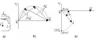
The difference in voltages U2ph and U1ph in the U-shaped circuit is determined by the voltage drop across the resistance Z12(Z12+jx12) caused by the current I12. This is determined by the voltage drop as the sum of vector I12r12, which is in phase with vector I12, and vector I12´jx12, which is 90° ahead of vector I12.
Voltage drop is the geometric (vector) difference between the voltage complexes of the beginning and end of the lines.
In Fig. The voltage drop is a vector, i.e.
the difference between the complex values at the ends of the lines is used to characterize the line mode.
The longitudinal component of the voltage drop DUk12 is the projection of the voltage drop onto the real axis or onto the voltage U2, DUk12=AC. The index “k” means that Uk12 is the projection onto the voltage of the end of the line U2.
Usually DUk12 is expressed through the data at the end of the line: U2, Pk12, Qk12.
The transverse component of the voltage drop dUк12 is the projection of the voltage drop onto the imaginary axis, jdUк12=SV. That. U1-U2=´I12´Z12=DUк12+jdUк12.
The value dUк12 determines the shift of the voltage vector at the beginning of the line (U1) by an angle d relative to the voltage vector at its end (U2).
The concept of voltage loss is often used - this is the algebraic difference between the voltage modules of the beginning (U1) and end (U2) of the lines.
In Fig. çU1ê– êU2ê=BP.
If the transverse component dUк12 is small (for example, in networks Unom £ 110 kV), then we can approximately assume that the voltage loss is equal to the longitudinal component of the voltage drop.
Voltage loss is an indicator of changes in the relative operating conditions of consumers at the beginning and end of the line.
Calculation of modes of power lines and electrical networks at a given load power
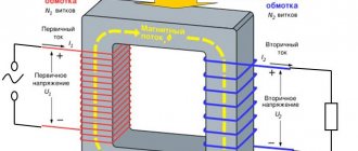
When energy is supplied along a line from beginning to end, reactive power losses occur. They are determined by the reactance of the line and the corresponding reactance of the equivalent circuit of this line. During energy transfer, there is also a loss of active power spent on heating the wires. Therefore, in the equivalent circuit one should distinguish between the total power before the resistance Z12(r12+jx12), Sн12 and after it Sк12.
Calculation of power line mode for a given load power and voltage at the end of the line
The voltage at the end of the line is set U2=const. The load power S2, voltage U2, resistance and conductivity of the line Z12=r12+jx12, v12 are known.
It is necessary to determine the voltage U1, the power at the end and at the beginning of the longitudinal part of the line Sк12, Sn12, the power loss DS12, the power at the beginning of the line S1. To check heating limits, the current in line I12 is sometimes determined.
The calculation is similar to the calculation for a given load current (I2), and consists of sequentially determining unknown powers and voltages from the end of the line to the beginning using Kirchhoff’s I law and Ohm’s law. We will use the power of three phases and line voltages.
Charging (capacitive) power of three phases at the end of the line:
–jQкс12=3I*кс12´U2ф=
Power at the end of the longitudinal part of the line according to Kirchhoff’s first law: Sk12=S2 – jQks12
Line power loss: DS12=3I212Z12=
The current at the beginning and at the end of the longitudinal branch of the line is the same.
The power at the beginning of the longitudinal branch of the line is greater than the power at the end by the amount of power loss in the line, i.e. Sn12=Sк12+DS12
Linear voltage at the beginning of the line according to Ohm's law is equal to:
U1=U2+I12Z12=U2+
Capacitive power at the beginning of the line: -jQнc12=
Power at the beginning of the line: S1=Sn12 – jQns12
Under the influence of the charging power Qc, the reactive power of the load Q2 at the end of the equivalent circuit decreases. A similar phenomenon occurs at the beginning of the equivalent circuit, where reactive power Qc reduces the reactive power at the beginning of the line.
This indicates that the charging power reduces the reactive power supplied from the station to the line to power the load. Therefore, charging power can conditionally be considered as a “generator” of reactive power.
In an electrical network line, both losses and generation of reactive power occur.
The difference between reactive powers at the beginning and end of the line depends on the ratio of losses and generation of reactive power.
Calculation of power line mode for a given load power and voltage at the beginning of the line
The voltage at the beginning of the line is set.
Substitution scheme:
U1=const. S2, U1, Z12=r12+jx12, в12 are known.
It is necessary to determine U2, Sk12, Sn12, DS12, S1
Because U2 is unknown, it is impossible to determine sequentially from the end of the line to the beginning; determine unknown currents and voltages using Kirchhoff’s first law and Ohm’s law.
Calculation of the magnitude of voltage drop and loss in power lines
Consumers of electrical energy operate normally when their terminals are supplied with the voltage for which the electric motor or device is designed. When transmitting electricity through wires, part of the voltage is lost due to the resistance of the wires and as a result, at the end of the line, i.e. at the consumer, the voltage is lower than at the beginning of the line.
A decrease in consumer voltage compared to normal affects the operation of the pantograph, be it a power or lighting load. Therefore, when calculating any power transmission line, voltage deviations should not exceed permissible norms; networks selected by load current and designed for heating are, as a rule, checked by voltage loss.
Voltage loss ΔU is the voltage difference at the beginning and end of the line (line section). ΔU is usually determined in relative units - in relation to the rated voltage. Analytically, the voltage loss is determined by the formula:
where P is active power, kW, Q is reactive power, kvar, ro is active line resistance, Ohm/km, xo is inductive resistance of the line, Ohm/km, l is line length, km, Unom is rated voltage, kV.
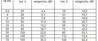
The values of active and inductive resistance (Ohm/km) for overhead lines made with A-16 A-120 grade wire are given in the reference tables. The active resistance of 1 km of aluminum (grade A) and steel-aluminum (grade AC) conductors can also be determined by the formula:
where F is the cross-section of the aluminum wire or the cross-section of the aluminum part of the AC wire, mm2 (the conductivity of the steel part of the AC wire is not taken into account).
According to the PUE (“Rules for the Construction of Electrical Installations”), for power networks the voltage deviation from normal should be no more than ± 5%, for electrical lighting networks of industrial enterprises and public buildings - from +5 to - 2.5%, for residential electrical lighting networks buildings and outdoor lighting ±5%. When calculating networks, they are based on the permissible voltage loss.
Taking into account the experience of designing and operating electrical networks, the following permissible values of voltage loss are accepted: for low voltage - from the busbars of the transformer room to the most remote consumer - 6%, and this loss is distributed approximately as follows: from the station or step-down transformer substation to the input into the room depending on the load density - from 3.5 to 5%, from the input to the most remote consumer - from 1 to 2.5%, for high voltage networks under normal operating conditions in cable networks - 6%, in overhead networks - 8%, during network emergency mode in cable networks – 10% and in air networks – 12%.
It is believed that three-phase three-wire lines with a voltage of 6-10 kV operate with a uniform load, that is, that each of the phases of such a line is loaded evenly. In low voltage networks, due to the lighting load, it can be difficult to achieve uniform distribution between the phases, so a 4-wire three-phase current system of 380/220 V is most often used. With this system, electric motors are connected to linear wires, and lighting is distributed between linear and zero wires. In this way, the load on all three phases is equalized.
When calculating, you can use both given powers and current values that correspond to these powers. In lines that extend for several kilometers, which, in particular, applies to lines with a voltage of 6-10 kV, it is necessary to take into account the influence of the inductive reactance of the wire on the voltage loss in the line.
For calculations, the inductive reactance of copper and aluminum wires can be taken equal to 0.32-0.44 Ohm/km, and a smaller value should be taken for small distances between wires (500-600 mm) and wire sections above 95 mm2, and a larger value for distances 1000 mm and above and sections 10-25 mm2.
The voltage loss in each wire of a three-phase line, taking into account the inductive resistance of the wires, is calculated using the formula
where the first term on the right side represents the active, and the second, the reactive component of the voltage loss.
The procedure for calculating a power transmission line for voltage loss with wires made of non-ferrous metals, taking into account the inductive reactance of the wires, is as follows:
1. We set the average value of inductive reactance for an aluminum or steel-aluminum wire to 0.35 Ohm/km.
2. We calculate the active and reactive loads P, Q.
3. Calculate the reactive (inductive) voltage loss
4. The permissible active voltage loss is defined as the difference between the specified line voltage loss and the reactive one:
5. Determine the wire cross-section s, mm2
where γ is the reciprocal of resistivity (γ = 1/ro is conductivity).
6. We select the nearest standard value s and find for it, using the reference table, the active and inductive reactance per 1 km of line (ro, xo).
7. We calculate the specified value of voltage loss using the formula.
The resulting value should not be greater than the permissible voltage loss. If it turns out to be more than permissible, then you will have to take a wire of a larger (next) cross-section and perform the calculation again.
For direct current lines, there is no inductive reactance and the general formulas given above are simplified.
Result of undervoltage
According to regulatory documents, losses on the line from the transformer to the most remote energy-loaded area for residential and public facilities should be no more than nine percent.
Losses of 5% are allowed to the main input, and 4% - from the input to the final consumer. For three-phase, three- or four-wire systems, the rating should be 400 V ± 10% under normal operating conditions.
Deviation of a parameter from the normalized value can have the following consequences:
- Incorrect operation of volatile installations, equipment, lighting devices.
- Failure of electrical appliances to operate when the input voltage is reduced, equipment failure.
- Reduced acceleration of the torque of electric motors at starting current, loss of energy taken into account, shutdown of motors when overheated.
- Uneven distribution of current load between consumers at the beginning of the line and at the remote end of a long wire.
- Lighting devices operate at half heat, resulting in underutilization of current power in the network and loss of electricity.
In operating mode, the most acceptable indicator of voltage loss in the cable is 5%. This is the optimal calculated value that can be accepted as acceptable for power grids, since in the energy industry currents of enormous power are transported over long distances.
Increased demands are placed on the characteristics of power lines. It is important to pay special attention to voltage losses not only on main networks, but also on secondary lines.
Calculation using formula
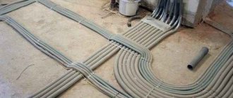
In practice, when installing trunk-type power lines and distributing cables to the end consumer with further distribution on site, copper or aluminum cable is used.
The resistivity for conductors is constant, for copper p = 0.0175 Ohm*mm2/m, for aluminum conductors p = 0.028 Ohm*mm2/m.
Knowing the resistance and current strength, it is easy to calculate the voltage using the formula U = RI and the formula R = p*l/S, where the following values are used:
- Wire resistivity - p.
- The length of the current-carrying cable is l.
- The cross-sectional area of the conductor is S.
- Load current in amperes - I.
- Conductor resistance - R.
- The voltage in the electrical circuit is U.
Using simple formulas on a simple example: it is planned to install several sockets in a detached extension of a private house. A copper conductor with a cross section of 1.5 square meters was selected for installation. mm, although for aluminum cable the essence of the calculations does not change.
Since the current passes back and forth through the wires, you need to take into account that the distance of the cable length will have to be doubled. If we assume that the sockets will be installed forty meters from the house, and the maximum power of the devices is 4 kW with a current of 16 A, then using the formula it is easy to calculate the voltage losses:
If we compare the obtained value with the nominal value for a single-phase line 220 V 50 Hz, it turns out that the voltage loss was: 220-14.93 = 205.07 V.
Such losses of 14.93 V are almost 6.8% of the input (nominal) voltage in the network. A value that is unacceptable for the power group of sockets and lighting fixtures, the losses will be noticeable: the sockets will pass current at less than full power, and the lighting fixtures will operate with less heat.
The power for heating the conductor will be P = UI = 14.93*16 = 238.9 W. This is the percentage of losses in theory without taking into account the voltage drop at the connection points of the wires and the contacts of the socket group.