How to make a soft-start carrier for power tools?
To extend the service life of a power tool, one of the important conditions is smooth starting when turned on.
But devices equipped with special circuits for this are expensive brands, like Bosch or Hilti. It is inconvenient, time consuming, and expensive to build a soft start unit into each tool. Such actions, moreover, lead to loss of warranty. But making a stationary socket with such a device is unprofitable, because mobility is important for working with power tools. The correct solution would be to make a carrier of sufficient length with a soft start unit (SPU) for the power tool.
In this case, we will get the absence of such unpleasant moments:
- Sparking of the armature and burnout of the lamellas on it;
- Accelerated grinding and burning of brushes;
- Early failure of the rotor and stator windings;
- Inrush of current into the electrical network during network connection;
- Acceleration of gear actuation;
- Increased risk of injury during starting and sudden jerking.
Disadvantages of angle grinders without soft start
Cordless angle grinder Metabo W 18 LTX 125 602174850 with soft start. Photo VseInstruments.ru
In addition to providing comfortable working conditions for the user, the angle grinder with soft start has a number of other advantages.
- The absence of a large starting current during the soft start of the angle grinder, which is several times higher than the nominal value of this parameter during operation, increases the reliability of the electrical part of the power tool. In this case, the winding wires do not experience overloads and do not crack, the commutator lamellas and brushes are not subject to wear from increased sparking, and processes that worsen the connection do not occur at the contact points.
- During a uniform increase in the speed to the nominal value, the angle grinder with a soft start does not experience increased dynamic loads that arise in its absence. An instantaneous acceleration of 6000 rpm or more does not leave its mark on the gear transmission and bearing units. They fail faster, so angle grinders without such a device are more often repaired.
Preparing to install the device
Making and using a carrier with a small power supply will save money on the purchase of new power tools, extending the service life of old ones. For domestic conditions, it is enough to use a 12A unit with the abbreviation KRRQD12A (see figure below).
Such a device should be used for starting and operating commutator types of power tool motors with a power of up to 2500 Watts. Having purchased a BPP, you should select an extension cord of sufficient length for operation. You also need to prepare a separate socket, a piece of stranded soft copper wire, tools, heat shrink or electrical tape. If the wires in the extension cord are soldered and not bolted, you will need a soldering iron, rosin, and solder.
Stages of installation work
If you have a minimum level of skills in electrical work and proper preparation, all actions will not take more than 15 minutes. Having prepared a copper wire with a cross-section of 2.5 mm, it should be stripped on both sides. Then, after removing the cover from the extension cord, you should remove the contact pad from it.
The contact pad is tinned at the soldering site, then the prepared copper wire is soldered to it. The same operation is repeated for the second site.
After careful soldering and careful laying of the wires, the cover of the extension cord is closed.
Then you need to take a square socket for outdoor installation, the BPP is placed in its body. Its dimensions are quite compact; there will be no problems with placement inside.
You should carefully install the wires of the unit in the socket. It must be connected to a wire break, regardless of whether it is phase or zero. It is impossible to supply zero and phase to the BPP at the same time. The connection diagram should look like this:
It makes no difference on which side of the block the input will be, and on which side we connect the output. After making connections, soldering and applying insulation to the place of possible twists, we assemble the socket with the block, close the lid, the assembled carrier is ready for use.
Now, by plugging the power tool into the resulting socket, we will get a smooth start. And this will save the tool, internal electrical networks, and reduce the likelihood of injury to the owner when starting work. A small and inexpensive soft starter can save money if you put in a little effort and spend a quarter of an hour.
If you accidentally plug in a tool equipped with a factory-made built-in soft start into such an outlet with a power supply, it will work. But at the same time we get a delay in starting the switching on of about 2 seconds.
If you liked the article, don’t forget to share it on social networks and subscribe to my channel!
source
Manufacturing a soft start socket
The most important requirement for such an outlet is its mobility. Therefore, a carrier will be useful for you.
With its help, you can smoothly launch the tool anywhere - in the garage, at the dacha, during the construction of your own house in various areas of the construction site.
First, the carrier must be disassembled.
The main power wires in it can be either soldered or connected to screw terminals.
Depending on this, your additional outlet will also be connected. This should be an additional socket near the carrying case in order to be able to immediately connect the instrument in various modes.
By the way, if you mistakenly plug in an angle grinder or circular saw that has a factory integrated soft start into an outlet that is also equipped with such a soft starter, then surprisingly everything will work. The only point is that there will be a delay in starting the saw or turning the blade for a couple of seconds, which is not very comfortable to work with and can become a burdensome task without getting used to it.
Here are real tests of such a connection, carried out by one master from YouTube BaRmAgLoT777. His comment after such tests on a Dremel type engraver, a Bosch drill, a Makita router, and an Interskol circular saw:
Next, to assemble the socket, take a stranded copper wire with a cross-section of 2.5 mm2 and strip its ends.
After this, you need to tin the contact pad on the carrier where this wire will be soldered.
Firmly solder the cable cores to these pads.
HOW TO INSTALL A SOFT START ON A CIRCULAR SAW (impeller, circular saw, etc.)
Carefully lay out the wires and close the extension cord.
Take a square external socket for installation on the outer surface of the walls, and try on a soft start unit in its body. Because it has small rectangular dimensions, it should fit there without any special problems.
Mount and secure the socket body on the same platform as the extension cord.
You connect the PP block into the gap of any wire, phase or neutral. Do not confuse it, phase and zero are not supplied to it at once, i.e. 220V.
It is installed on one of the wires.
Also for this BPP, there is no difference on which side to make the entrance and on which side to exit. The twists are soldered and insulated with heat shrink.
After this, all the insides of the socket are assembled into a housing and all that remains is to close the entire structure with a lid.
At this point, the entire reworking of the carrying case and the manufacture of the socket can be considered complete. It will take you less than 15 minutes.
How to smoothly start a power tool from a regular outlet.
An ordinary socket, if modified a little, can extend the life of any of your tools - an angle grinder, a circular saw, a trimmer, etc.
All you need for this is a small soft start box costing about 200 rubles. For example, a brand like KRRQD12A.
It is well known that not every tool is equipped with such soft start circuits. They mainly come in expensive models from well-known brands Bosch, Hilti, and DeWalt. Moreover, both in the network line and in the battery one.
A power tool without such a device has a bunch of disadvantages:
When working with a miter saw with a PP, the blade will not stray from the prepared cutting point. Which is important for non-professional carpenters.
If at your dacha or in your house at the initial stage of construction there is no electricity yet and you use a generator, then sooner or later you will understand that without a soft start unit (soft start unit) with sharp initial currents, the generator will not last long. Therefore, such a thing can save not only the tool, but also emergency power supplies.
You can, of course, independently build a BPP into the inside of the same grinder or trimmer, but not everyone wants to disassemble the equipment and tinker with the insides.
Plus, opening a new case will void the warranty. Therefore, the best use for the KRRQD12A unit is external connection.
This box is designed for a current of 12 Amps.
There is also a more powerful 20A model.
What is typical is that they have the same dimensions, but the difference in price is a couple of tens of rubles.
It would seem better to take it, but for a standard 16A socket the first option is more profitable. There will be no desire to connect a more powerful load and thereby burn all the contacts.
DIY craftsmen, of course, assemble similar circuits with their own hands, based on VTA 12-600 or other thyristors, capacitors, a dinistor and a couple of small resistors. You can find many examples of schemes on the Internet.
But for the average user of the instrument, it is much easier to buy all this in a ready-made compact case. You can order a similar block using the link here.
By the way, be careful, there are similar devices, but with three wires. For example XS-12/D3.
Or other models that look similar to KRRQD.
But they are assembled on a slightly different principle and need to be installed after the START button, in the instrument itself. Voltage should be applied to them only at the moment the grinder's start button is closed and immediately disappear after it is released.
Speed controller and soft start - what are they for?
Modern grinders use two important functions that increase the reliability and safety of the tool:
- speed controller - a device designed to change the number of engine revolutions in various operating modes;
- soft start - a circuit that ensures a slow increase in engine speed from zero to maximum when the device is turned on.
They are used in electromechanical tools that use a commutator motor in their design. Helps reduce wear on the mechanical part of the unit during switching on. They reduce the load on the electrical elements of the mechanism by putting them into operation gradually.
As studies of the properties of materials have shown, the most intense production of friction units occurs during a sharp transition from a state of rest to a mode of rapid movement. For example, one start of an internal combustion engine in a car is equivalent to 700 km of mileage in terms of wear on the piston group.
When the power is turned on, an abrupt transition occurs from a state of rest to rotation of the disk at a speed of 2.5–10 thousand revolutions per minute. Those who have worked with an angle grinder are well aware of the feeling that the machine simply “rips out of your hands.” It is at this moment that the overwhelming number of breakdowns associated with the mechanical part of the unit occur.
The stator and rotor windings experience no less load. The commutator motor starts in short circuit mode, the electromotive force is already pushing the shaft forward, but inertia does not yet allow it to rotate. A jump in starting current occurs in the coils of the electric motor. And although they are structurally designed for such work, sooner or later a moment comes (for example, during a power surge in the network) when the winding insulation cannot withstand and an interturn short circuit occurs.
When soft start circuits and changes in engine speed are included in the electrical circuit of the tool, all of the above problems automatically disappear. Among other things, the problem of voltage “dip” in the general network at the moment of starting a hand tool is solved. This means that the refrigerator, TV or computer will not be at risk of “burning out”. And the safety circuit breakers on the meter will not operate and cut off the current in the house or apartment.
The soft start circuit is used in angle grinders of medium and high price categories, the speed control unit is used mainly in professional models of angle grinders.
Soft start on a hand-held circular saw
#1 saper24
Good day everyone. Does anyone know how to kill a soft start on a saw? In particular Interskol. I'm not very good at electrical engineering. It’s really necessary, it’s impossible to work with this rubbish. What needs to be pulled out there?
#2 SergDemin
I wouldn't recommend it. A soft start not only removes the jerk on your hands, but also the current surge at the moment of switching on. I have changed many rotors in power tools due to an internal winding break. And they arise precisely because of the current surge. I'm where the soft start is, or the regulator is on the trigger - not a single one. And it’s easy to throw away - the wires from the engine directly to the switch. To be more precise, photos of the insides are needed.
#3 kot_obormot
Is it worth throwing out a soft start on a circular machine, not an ushm/pshm?
#4 Victor 69
photo, with numbers, I’ll tell you what’s stopping you from living.
#5 Lohus
It's impossible to work with this crap
In the sense that when the disk is inserted into the cut, it cannot unwind? Or does it just take a long time to accelerate?
I have a 2kW fin and a 200mm disc, without a smooth one, when turning it on you need to hold it tighter.
Post edited by Lohus: 19 May 2021 23:13
#6 Artisan
Is it worth throwing out a soft start on a circular machine, not an ushm/pshm?
#7 saper24
I have a personal Bosch without soft start, everything is fine. And before that, all the workers were without it. They died from falls, mostly from cutting off gears. And these eccentrics bought this for work. When you press the button, nothing happens for the first second. When I first picked it up I thought there was no electricity. And it spins up so slowly that you get tired of waiting, and there’s no time to wait. They were putting together two monoliths under the stairs and it was so infuriating that I wanted to slam into the corner. My hands are fine, I can put off a shift without smoking breaks. So a saw with 190 circles is not my rival. Where there are a bunch of short cuts, it takes half a day to unwind, not to mention stopping to change position when cutting long materials. Everything is on the ground and knees, complete distortions. In its own cut it no longer unwinds. We don’t need precision, they don’t provide workbenches, work in extreme conditions and palace delights for country craftsmen spoil our blood beyond childishness. There was an angle grinder, like me, thank God it was covered, by the way, the winding burned out. I couldn’t make an 80 meter cut in concrete to its full depth)
How to install
It is not difficult to install a soft start or soft running system on a power tool yourself. To do this, you first need to disassemble the handle of the tool, in the place where the start button is located. Then you need to remove the contacts from the switch and connect the module to the open circuit between the electric motor and the start button. The output of the soft starter must be connected to the electric motor. All contacts must be connected to each other using a soldering iron and then insulated.
The contacts can also be twisted together and insulated using heat-shrink tubing or simple electrical tape. At the final stage of assembly, the power cable is reconnected to the power tool, and the body and handle are installed in its original position.
In addition, if desired, each user can independently create a soft start system using a special KR1182PM1R board. To make such a device at home, you will need to purchase the following materials and components:
- solder;
- soldering iron;
- microcircuit KR1182PM1R;
- a set of capacitors, resistors and triacs.
The electronic circuit diagram of this device can be found on the Internet. The main element in this soft launch block is the board. The power part of this unit is represented by triacs. The main advantages of this unit are its ease of use (there is no need to further configure the soft starter after its final assembly), and it is suitable for any tool operating on a 220V AC network.
If necessary, such a unit can be installed inside the equipment itself or connected to the break point in the power cable. It is best to connect such a soft starter directly to the outlet from which the equipment will ultimately be powered.
General information
The stator of an electric motor is an inductance coil; therefore, there are resistances with an active and reactive component.
When electric current flows through radioelements that have resistance with an active component, losses occur due to the conversion of part of the power into thermal energy. For example, a resistor and the stator windings of an electric motor have a resistance with an active component. Calculating active resistance is not difficult, since the phases of the current (I) and voltage (U) coincide. Using Ohm's law for a section of a circuit, you can calculate the active resistance: R = U/I. It depends on the material, cross-sectional area, length and its temperature.
If the current passes through a reactive type of element (with capacitive and inductive characteristics), then, in this case, a reactive R appears. An inductor that has practically no active resistance (the calculations do not take into account the R of its windings). This type of R is created due to the Electromotive Force (EMF) of self-induction, which is directly proportional to the inductance and frequency I passing through its turns: Xl = wL, where w is the angular frequency of the alternating current (w = 2*Pi*f, and f - network current frequency) and L - inductance (L = n * n / Rm, n - number of turns and Rm - magnetic resistance).
When the electric motor is turned on, the starting current is 7 times greater than the rated current (the current consumed during operation of the tool) and the stator windings heat up. If the stator coil is old, then an interturn short circuit may occur, which will lead to failure of the power tool. To do this, you need to use a soft starter for a power tool.
One of the methods for reducing the inrush current (Ip) is to switch windings. To implement it, 2 types of relays (time and load) and the presence of three contactors are required.
Starting an electric motor with windings connected in a star type is possible only with 2 contactors not simultaneously closed.
After a certain time interval, which is set by a time relay, one of the contactors is turned off and another one, not previously used, is turned on. Thanks to this alternation of switching on the windings, the inrush current decreases. This method has a significant drawback, since when two contactors are simultaneously closed, a short-circuit current occurs. However, when using this method, the windings continue to heat up. Another way to reduce the starting current is to control the frequency of starting the electric motor. The principle of this approach is the frequency change of the supply U. The main element of this type of soft starter is a frequency converter, consisting of the following elements:
- Rectifier.
- Intermediate chain.
- Inverter.
- Electronic control circuit.
The rectifier is made of powerful diodes or thyristors , acting as a converter U of the network supply into a direct pulsating current. The intermediate circuit smoothes out the pulsating direct current at the output of the rectifier, which is collected on large capacitors. An inverter is necessary to directly convert the signal at the output of the intermediate circuit into a signal of the amplitude and frequency of the variable component. An electronic control circuit is needed to generate the signals necessary to control the rectifier or inverter.
Selecting a soft starter
When an asynchronous motor is turned on, a short circuit current appears in its rotor for a short time, the strength of which, after gaining speed, decreases to the nominal value corresponding to the power consumed by the electric machine. This phenomenon is aggravated by the fact that at the moment of acceleration the torque on the shaft increases abruptly. As a result, protective circuit breakers may trip, and if they are not installed, then other electrical devices connected to the same line may fail. And in any case, even if an accident does not occur, when starting electric motors, increased energy consumption is observed. To compensate or completely eliminate this phenomenon, soft starters (SFDs) are used.
How is a soft start implemented?
To smoothly start the electric motor and prevent an inrush current, two methods are used:
- Limit the current in the rotor winding. To do this, it is made consisting of three coils connected in a star configuration. Their free ends lead to slip rings (collectors) mounted on the shaft shank. A rheostat is connected to the collector, the resistance of which is maximum at the time of start-up. As it decreases, the rotor current increases and the motor spins up. Such machines are called wound-rotor motors. They are used in crane equipment and as traction electric motors for trolleybuses and trams.
- Reduce voltage and current supplied to the stator. In turn, this is implemented using:
a) autotransformer or rheostat;
b) key circuits based on thyristors or triacs.
It is the key circuits that are the basis for the construction of electrical devices, which are usually called soft starters or soft starters. Please note that frequency converters also allow you to start an electric motor smoothly, but they only compensate for a sharp increase in torque without limiting the starting current.
The operating principle of the key circuit is based on the fact that the thyristors are unlocked for a certain time at the moment the sinusoid passes zero. Usually in that part of the phase when the voltage rises. Less often - when it falls. As a result, a pulsating voltage is recorded at the output of the soft starter, the shape of which is only approximately similar to a sinusoid. The amplitude of this curve increases as the time interval during which the thyristor is unlocked increases.
Read also: Who discovered the chemical element copper
Softstarter selection criteria
In order of decreasing degree of importance, the device selection criteria are arranged in the following sequence:
- Power.
- Number of controlled phases.
- Feedback.
- Functionality.
- Control method.
- Additional features.
The main parameter of the soft starter is the value of Inom - the current strength for which the thyristors are designed. It should be several times greater than the current passing through the motor winding when it reaches rated speed. The frequency depends on the severity of the launch. If it is light - metal-cutting machines, fans, pumps, then the starting current is three times higher than the rated current. Hard starting is typical for drives with a significant moment of inertia. These are, for example, vertical conveyors, sawmills, and presses. The current is five times higher than the rated current. There is also a particularly difficult start-up that accompanies the operation of piston pumps, centrifuges, and band saws. Then the Inom of the softstarter should be 8-10 times greater.
The severity of the launch also affects the time it takes to complete. It can last from ten to forty seconds. During this time, the thyristors become very hot as they dissipate some of the electrical power. To repeat, they need to cool down, and this takes the same amount of time as the working cycle. Therefore, if the technological process requires frequent switching on and off, then choose a soft starter for heavy starting. Even if your device is not loaded and picks up speed easily.
One, two or three phases can be controlled. In the first case, the device mitigates the increase in starting torque to a greater extent than in current. The most commonly used are two-phase starters. And for cases of heavy and particularly difficult starting - three-phase.
SCP
can work according to a given program - increase the voltage to the nominal value within a specified time. This is the simplest and most common solution. The presence of feedback makes the management process more flexible. The parameters for it are the comparison of voltage and torque or the phase shift between the rotor and stator currents.
Ability to work on acceleration or braking. The presence of an additional contactor, which bypasses the key circuit and allows it to cool, and also eliminates phase asymmetry due to a violation of the sinusoid shape, which leads to overheating of the windings.
It can be analog, by rotating potentiometers on the panel, and digital, using a digital microcontroller.
All types of protection, energy saving mode, the ability to start with a jerk, work at a reduced speed (pseudo-frequency regulation).
A correctly selected soft starter doubles the working life of electric motors and saves
up to 30 percent
of electricity.
Why do you need a soft starter?
Increasingly, when starting electric drives of pumps and fans, a soft start device (soft starter) is used. What is this connected with? In our article we will try to highlight this issue.
Induction motors have been in use for over a hundred years, and during that time relatively little has changed in their operation. The startup of these devices and the problems associated with it are well known to their owners. Inrush currents lead to voltage sags and wiring overloads, resulting in:
some electrical equipment may turn off spontaneously;
possible equipment failure, etc.
A timely installed, purchased and connected softstarter allows you to avoid unnecessary waste of money and headaches.
What is starting current
The principle of operation of asynchronous motors is based on the phenomenon of electromagnetic induction. The build-up of reverse electromotive force (emf), which is created by applying a changing magnetic field during engine starting, leads to transients in the electrical system. This transient may affect the power system and other equipment connected to it.
During startup, the electric motor accelerates to full speed. The duration of the initial transients depends on the design of the unit and the characteristics of the load. The starting torque should be the greatest, and the starting currents should be the smallest. The latter entail detrimental consequences for the unit itself, the power supply system and the equipment connected to it.
During the initial period, the inrush current can reach five to eight times the full load current. During motor starting, the cables are forced to carry more current than during the steady state period. The voltage drop in the system will also be much greater at start-up than during stable operation - this becomes especially obvious when starting a powerful unit or a large number of electric motors at the same time.
Motor protection methods
As the use of electric motors has become widespread, overcoming problems starting them has become a challenge. Over the years, several methods have been developed to solve these problems, each with its own advantages and limitations.
Recently, significant advances have been made in the use of electronics in power control for motors. Increasingly, soft starters are used when starting electric drives of pumps and fans. The thing is that the device has a number of features.
A special feature of the starter is that it smoothly supplies voltage to the motor windings from zero to the rated value, allowing the motor to smoothly accelerate to maximum speed. The mechanical torque developed by an electric motor is proportional to the square of the voltage applied to it.
During the startup process, the soft starter gradually increases the supplied voltage, and the electric motor accelerates to the rated rotation speed without large torque and peak current surges.
Types of soft starters
Today, for the smooth start-up of equipment, three types of soft starters are used: with one, two and all controlled phases.
The first type is used for a single-phase motor to provide reliable protection against overload, overheating and reduce the influence of electromagnetic interference.
As a rule, the second type of circuit includes a bypass contactor in addition to the semiconductor control board. Once the motor has reached rated speed, the bypass contactor is activated and provides direct voltage to the motor.
The three-phase type is the most optimal and technically advanced solution. It provides limitation of current and magnetic field strength without phase imbalances.
Why do you need a soft starter?
Due to their relatively low price, the popularity of soft starters is gaining momentum in the modern market of industrial and household appliances. A soft starter for an asynchronous electric motor is necessary to extend its service life. The big advantage of a softstarter is that the start is carried out with smooth acceleration, without jerking.
Still have questions? ENERGOPUSK specialists will answer your questions: 8-800-700-11-54
(8-18, Mon-Tue)
Operating principle
During the start-up of a commutator-type electric motor, a significant short-term increase in current consumption occurs, which causes premature failure of the power tool and requires it to be repaired. Electrical parts wear out (current exceeds 7 times) and mechanical parts (sharp start). To organize a “soft” start, soft start devices (hereinafter referred to as soft starters) should be used. These devices must meet the basic requirements:
- Smooth increase in load.
- Possibility of starting the engine at certain time intervals.
- Providing protection against linear surges of U, phase loss (for a 3-phase electric motor) and various interference of the electrical component.
- Significantly increased service life.
The most widely used are triac soft starters, the operating principle of which is smooth regulation of U by adjusting the opening angle of the triac junction. The triac must be connected directly to the motor windings and this allows you to reduce the starting current from 2 to 5 times (depending on the triac and control circuit). The main disadvantages of triac soft starters are the following:
- Complex schemes.
- Overheating of windings during prolonged startup.
- Problems with starting the engine (leads to significant heating of the stator windings).
Application in an angle grinder
When starting an angle grinder (angle grinder), high dynamic loads appear on the tool parts.
Expensive models are equipped with soft starters, but not ordinary varieties, for example, angle grinders. An inertial jerk can tear an angle grinder out of your hands, and this poses a threat to life and health. In addition, when starting the electric motor of the tool, an overload of current occurs and, as a result, wear of the brushes and significant heating of the stator windings, wear out of the gearbox and possible destruction of the cutting disk, which can crack at any time and cause harm to health, and maybe even life. The tool needs to be secured and for this you should make an angle grinder with speed control and soft start with your own hands.
Installation of a soft start unit (SPU) for trimming
Expensive tools are not always relevant for household use. But cheaper options are not equipped with special electronic current control boards, so soft start is not provided, which often causes premature failure of the device. A small do-it-yourself modernization allows you to protect electric saws (circular saws and crosscut saws), as well as drills and grinders from overload, and this scheme is not so difficult to repeat on your own.
Homemade options
There are many schemes for modernizing power tools using soft starters. Among all varieties, devices based on triacs are widely used. A triac is a semiconductor element that allows you to smoothly regulate power parameters. There are simple and complex circuits that differ in design options, as well as in the supported power of the connected power tool. The design includes internal ones, which allow them to be built inside the case, and external ones, manufactured in the form of a separate module, which acts as a speed limiter and starting current when starting the angle grinder directly.
The simplest scheme
A soft starter with speed control on a thyristor KU 202 is widely used due to its very simple design (diagram 1). Connecting it does not require any special skills. Radio elements for it are very easy to obtain. This regulator model consists of a diode bridge, a variable resistor (acts as a U regulator) and a thyristor tuning circuit (supplying U to the control output with a nominal value of 6.3 volts) from a domestic manufacturer.
Scheme 1. Electrical diagram of the indoor unit with speed control and soft start (electrical circuit diagram)
Due to the size and number of parts, this type of regulator can be built into the body of a power tool.
In addition, the variable resistor knob should be removed and the speed controller itself can be modified by integrating a button in front of the diode bridge. The basic principle of operation is to regulate the speed of the electric motor of the tool by limiting the power in manual mode. This circuit allows you to use power tools with a power of up to 1.5 kW. To increase this indicator, it is necessary to replace the thyristor with a more powerful one (information about this can be found on the Internet or in a reference book). In addition, you need to take into account the fact that the thyristor control circuit will differ from the original one. KU 202 is an excellent thyristor, but its significant drawback is its configuration (selection of parts for the control circuit). To implement a soft start in automatic mode, scheme 2 is used (soft starter on a microcircuit).
Soft start on a chip
The best option for manufacturing a soft starter is a soft starter circuit with one triac and a microcircuit that controls the smooth opening of a pn type transition. The device is powered from a 220 V network and is easy to assemble yourself. A very simple and universal soft start circuit for an electric motor also allows you to regulate the speed (diagram 2). The triac can be replaced with the same one or with characteristics exceeding the original ones, according to the reference book of semiconductor-type radioelements.
Scheme 2. Scheme for soft start of a power tool
The device is implemented on the basis of the KR118PM1 microcircuit and a triac. Due to the versatility of the device, it can be used for any tool. It does not require configuration and is installed into the power cable.
When the electric motor starts, U is supplied to KR118PM1 and the charge of capacitor C2 gradually increases. The thyristor opens gradually with a delay depending on the capacitance of the control capacitor C2. With a capacitance of C2 = 47 μF, there is a delay at startup of about 2 seconds. It depends directly proportionally to the capacitance of the capacitor (with a larger capacitance, the startup time increases). When the angle grinder is turned off, capacitor C2 is discharged using resistor R2, the resistance of which is 68 k, and the discharge time is about 4 seconds.
To regulate the speed, you need to replace R1 with a variable resistor. When changing the parameter of the variable resistor, the power of the electric motor changes. R2 changes the amount of current flowing through the triac input. The triac needs cooling and, therefore, a fan can be built into the module housing.
The main function of capacitors C1 and C3 is to protect and control the chip. The triac should be selected based on the following characteristics: direct U should be 400..500 V and direct current should be at least 25 A. With such ratings of radio elements, it is possible to connect a tool with a power from 2 kW to 5 kW to the soft starter.
Thus, to start electric motors of various tools, it is necessary to use factory-made or home-made soft starters. Soft starters are used to increase the service life of the tool. When starting the engine, there is a sharp increase in current consumption by 7 times. Because of this, the stator windings may burn out and the mechanical part may wear out. Soft starters can significantly reduce the starting current. When making a soft starter yourself, you need to follow safety rules when working with electricity.
source
Control circuit connections
Starting and stopping the electric motor is realized by two- or three-wire circuits.
The drive starts by pressing a button. The electric machine is stopped by pressing again.
When choosing a three-wire circuit, smooth starting and braking of the engine is carried out by pressing the “start” and “stop” buttons.
The soft starter of this model allows you to adjust the starting voltage in the range from 30% to 75% of the nominal value of the electrical network. The default is 50%. The duration of voltage rise and fall is adjustable in the range from 2 to 20 seconds. This value determines the acceleration and stopping time of the electric machine.
All electrical connections are made with cables with copper conductors, grades and cross-sections recommended by the manufacturers. Drive settings and soft starter programming are carried out in accordance with the algorithm specified by the manufacturer. Before a test run, to check the operability of the drive, it is necessary to check the connection diagram and the correctness of the settings.
Alexander Sitnikov (Kirov region)
The circuit discussed in the article allows for shock-free starting and braking of the electric motor, increasing the service life of the equipment and reducing the load on the electrical network. A soft start is achieved by regulating the voltage on the motor windings with power thyristors.
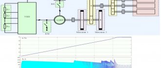
Soft start devices (SPDs) are widely used in various electric drives. The block diagram of the developed soft starter is shown in Figure 1, and the operation diagram of the soft starter is shown in Figure 2. The basis of the soft starter is three pairs of back-to-back thyristors VS1 - VS6, connected to the break of each phase. Soft start is carried out due to gradual
Read also: How to use a foam gun correctly
increasing the mains voltage applied to the motor windings from a certain initial value Un to the nominal Unom. This is achieved by gradually increasing the conduction angle of thyristors VS1 - VS6 from the minimum value to the maximum during the time Tstart, called the start time.
Typically, the value of Unat is 30...60% of Unom, so the starting torque of the electric motor is significantly less than if the electric motor is connected to full mains voltage. In this case, the drive belts are gradually tensioned and the gear wheels of the gearbox are smoothly engaged. This has a beneficial effect on reducing the dynamic loads of the electric drive and, as a result, helps to extend the service life of the mechanisms and increase the interval between repairs.
The use of a soft starter also makes it possible to reduce the load on the electrical network, since in this case the starting current of the electric motor is 2–4 rated motor current, and not 5–7 rated current, as with direct starting. This is important when powering electrical installations from energy sources of limited power, for example, diesel generator sets, uninterruptible power supplies and low-power transformer substations
(especially in rural areas). After the start-up is completed, the thyristors are bypassed by a bypass (bypass contactor) K, due to which during the time Trab the thyristors do not dissipate power, which means energy is saved.
When the engine is braking, the processes occur in the reverse order: after the contactor K is turned off, the conduction angle of the thyristors is maximum, the voltage on the motor windings is equal to the mains voltage minus the voltage drop across the thyristors. Then the conduction angle of the thyristors during the time Ttorm decreases to the minimum value, which corresponds to the cut-off voltage Uots, after which the conduction angle of the thyristors becomes zero and voltage is not applied to the windings. Figure 3 shows current diagrams of one of the motor phases with a gradual increase in the conduction angle of the thyristors.
Figure 4 shows fragments of the electrical circuit diagram of the soft starter. The full diagram is available on the magazine's website. For its operation, a voltage of three phases A, B, C of a standard 380 V network with a frequency of 50 Hz is required. The windings of the electric motor can be connected either by a star or a delta.
Inexpensive devices of type 40TPS12 in TO-247 housing with direct current Ipr = 35 A are used as power thyristors VS1 - VS6. The permissible current through the phase is Iadd = 2Ipr = 70 A. We will assume that the maximum starting current is 4Ir, which means that Inom (due to connecting a higher power motor or too short start time), the starting process will be stopped, since the QF1 circuit breaker with a specially selected characteristic will operate.
Damping RC chains R48, C20, C21, R50, C22, C23, R52, C24, C25 are connected in parallel to the thyristors, preventing false switching on of the thyristors, as well as varistors R49, R51 and R53, absorbing overvoltage pulses over 700 V. Bypass relays K1, K2, K3 type TR91-12VDC-SC-C with a rated current of 40 A shunt the power thyristors after the start is completed.
The control system is powered from a transformer power supply powered from the phase-to-phase voltage Uav. The power supply includes step-down transformers TV1, TV2, diode bridge VD1, current-limiting resistor R1, smoothing capacitors C1, C3, C5, noise suppression capacitors C2, C4, C6 and linear stabilizers DA1 and DA2, providing voltages of 12 and 5 V, respectively.
The control system is built using a DD1 microcontroller type PIC16F873. The microcontroller issues control pulses for thyristors VS1 – VS6 by “igniting” optosimistors ORT5-ORT10 (MOC3052). To limit the current in the control circuits of thyristors VS1 - VS6, resistors R36 - R47 are used. Control pulses are applied simultaneously to two thyristors with a delay relative to the beginning of the phase-to-phase voltage half-wave. Synchronization circuits with mains voltage consist of three similar units, consisting of charging resistors R13, R14, R18, R19, R23, R24, diodes VD3 - VD8, transistors VT1 - VT3, storage capacitors C17 - C19 and optocouplers OPT2 - OPT4. From output 4 of optocouplers OPT2, OPT3, OPT4, pulses with a duration of approximately 100 μs are received at the inputs of the microcontroller RC2, RC1, RC0, corresponding to the beginning of the negative half-wave of phase voltages Uab, Ubc, Uca.
The operation diagrams of the synchronization unit are shown in Figure 5. If we take the top graph as the mains voltage Uav, then the middle graph will correspond to the voltage on capacitor C17, and the bottom graph will correspond to the current through the photodiode of the ORT2 optocoupler. The microcontroller registers the clock pulses arriving at its inputs, determines the presence, the order of alternation, the absence of “sticking” of phases, and also calculates the delay time of the thyristor control pulses. The inputs of the synchronization circuits are protected from overvoltage by varistors R17, R22 and R27.
Using potentiometers R2, R3, R4, parameters corresponding to the soft starter operation diagram shown in Figure 2 are set; respectively, R2 – Tstart, R3 – Tbrake, R4 – Unstart Uots. The setpoint voltages from the motors R2, R3, R4 are supplied to the inputs RA2, RA1, RA0 of the DD1 microcircuit and converted using an ADC. The starting and braking times are adjustable from 3 to 15 s, and the initial voltage is adjustable from zero to a voltage corresponding to the thyristor conduction angle of 60 electrical degrees. Capacitors C8 - C10 are noise suppressing.
Read also: Reducer for a small gas cylinder
The “START” command is issued by closing contacts 1 and 2 of the XS2 connector, and a log appears at output 4 of the optocoupler OPT1. 1; capacitors C14 and C15 suppress oscillations arising due to “bouncing” of contacts. The open position of contacts 1 and 2 of the XS2 connector corresponds to the “STOP” command. Switching the launch control circuit can be realized with a latching button, toggle switch or relay contacts.
Power thyristors are protected from overheating by a B1009N thermostat with normally closed contacts located on the heat sink. When the temperature reaches 80°C, the thermostat contacts open, and a log level is sent to the RC3 input of the microcontroller. 1, indicating overheating.
LEDs HL1, HL2, HL3 serve as indicators of the following states:
- HL1 (green) “Ready” – no emergency conditions, ready to launch;
- HL2 (green) “Operation” – a blinking LED means that the soft starter is starting or braking the engine, constant light means it is working on bypass;
- HL3 (red) “Alarm” – indicates overheating of the heat sink, absence or “sticking” of phase voltages.
The bypass relays K1, K2, K3 are turned on by supplying a log to the microcontroller. 1 to the base of transistor VT4.
Programming of the microcontroller is in-circuit, for which connector XS3, diode VD2 and microswitch J1 are used. Elements ZQ1, C11, C12 form the clock generator start circuit, R5 and C7 are the power reset circuit, C13 filters noise along the microcontroller power buses.
Figure 6 shows a simplified algorithm for the operation of the soft starter. After initializing the microcontroller, the Error_Test subroutine is called, which determines the presence of emergency situations: overheating of the heat sink, inability to synchronize with the mains voltage due to phase loss, incorrect connection to the network or strong interference. If the emergency situation is not recorded, then the Error variable is assigned the value “0”, after returning from the subroutine the “Ready” LED lights up, and the circuit goes into standby mode for the “START” command. After registering the “START” command, the microcontroller performs an analogue-to-digital conversion of the setting voltages on the potentiometers and calculates the Tstart and Ustart parameters, after which it issues control pulses for the power thyristors. At the end of the start-up, the bypass is turned on. When the engine is braking, control processes are performed in the reverse order.
Practice has shown that we increasingly think about soft start devices only when we see a failed drive mechanism gearbox, when we have to change prematurely worn out and no longer useful drive belts, when we fix ruptured pipes, when there is a drop in supply voltage when turning on one or another. another unit knocks out all the protections and infuriates not only you, but also your neighbors.
The list of such unpleasant moments can be continued as long as desired, but the above facts should be enough to make you think: for what reason is all this happening?
A timely purchased and connected softstarter will allow you to avoid unnecessary costs and sometimes unnecessary headaches.
A soft start device is a mechanical, electrical or electromechanical equipment necessary for smooth start/stop of electric motors with a small starting moment of the working machine.