How everything works
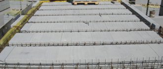
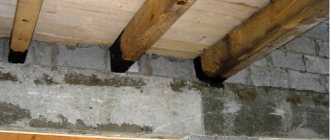
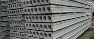
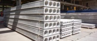
Coniferous wood is the most popular material for the construction of interfloor and attic floors in a private house. The main reason is obvious - the low price compared to monolithic reinforced concrete or ready-made slabs.
In addition: a floor on wooden beams, unlike a slab floor, can be installed without the services of loading equipment, which also provides significant savings. It differs favorably from monolithic in that it does not require the construction of formwork.
- Ensure their sufficient load-bearing capacity under the calculated long-term loads;
- If we are talking about a ceiling above an unheated basement or under an unused attic, organize sufficiently effective thermal insulation that meets the requirements of the climate zone in which you live.
Perform effective interfloor sound insulation;
Methods for connecting rafters to beams
So you have two main options:
- First install the floor beams, mounting them into the walls, thereby creating a layered rafter system.
- Assemble the rafter trusses on the ground and lift them to the roof ready-made, while the bottom tightening of the trusses will simultaneously serve as a support-beam for the future attic floor.
Each of these methods has its pros and cons, but the methods of fastening are different - for trusses it is usually fastened with metal or wooden plates, and for assembly on the roof - chipping and tenoning.
Hanging rafters: tie and beam in one role
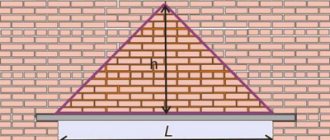
If we are talking about a small construction project, such as a garage, a bathhouse or a change house, then it is enough to simply make roof trusses on the ground, and only then lift them onto the walls of the building, securing them to special Mauerlat pins. Here, the floor beams are an integral part of the trusses themselves, and this is the case when the tie in the truss also serves as a support for the attic floor.
Here's how it works in practice:
But about the options when the rafters rest on the floor beams, and do not create a single system with them, we will now look in more detail.
Layered rafters: support on beams at several points
Here is a modern master class in building a classic attic roof, in which the rafters are supported on floor beams directly on the roof, rather than building trusses on the ground:
Here, the floor beams are no longer part of a single rafter truss, but an independent element on which the entire rafter system rests. Moreover, the support occurs not only on the sides of the beam, but along its entire length.
Load capacity calculation
How to calculate wooden floor beams with known span and pitch?
general information
We have already mentioned the maximum span: it is limited by the length of the supplied timber. However, the optimal span for wooden load-bearing structures is considered to be 2.5 - 4 meters. Among other things, a smaller span makes it possible to use timber of a smaller cross-section, which reduces the cost of the floor structure.
It is optimal to use timber with a rectangular cross-section as beams. Its height should be in a ratio of 1.4:1 to its width. In this case, we obtain maximum load-bearing capacity at, again, minimal costs.
However: the actual cross-sections of the wooden beams cause them to deviate somewhat from the optimal proportion of sizes.
The beam must rest on the wall at least 12 centimeters in length from the edge.
The edge resting on the wall is waterproofed on all sides except the end. When sealing the ends with moisture-impermeable material, the ends will sooner or later rot due to lack of natural drying.
When calculating interfloor slabs, the calculated value of the full load (self-weight of the slab and operational load) of 400 kgf/m2 is usually used. However, for unused attics this value can be reduced.
A cold attic is undemanding in terms of floor strength.
Section tables
Let's start by selecting the cross-section of a rectangular beam for a load of 400 kgf/m2 at different values of the span and pitch between the beams.
| Step/span | 200 cm | 300 cm | 400 cm | 500 cm | 600 cm |
| 60 cm | 7.5x10 cm | 7.5x20 cm | 10x20 cm | 12.5x20 cm | 15x22.5 cm |
| 100 cm | 7.5x10 cm | 10x17.5 cm | 12.5x20 cm | 15x22.5 cm | 17.5x25 cm |
When constructing an attic floor under an unused attic, the design load can be in the range of 150 - 350 kgf/m2. With a step between beams of one meter, their sections in centimeters should be as follows:
| Design load, kgf/m2/span, cm | 300 | 400 | 500 | 600 |
| 150 | 5x14 | 6x18 | 8x20 | 10x22 |
| 200 | 5x16 | 7x18 | 10x20 | 14x22 |
| 250 | 6x160 | 7x20 | 12x20 | 16x22 |
| 350 | 7x160 | 8x20 | 12x22 | 20x22 |
Another table contains the minimum diameters of round beams (rounded logs) at a load of 400 kgf/m2 and a step of 1 meter.
| Span, cm | Log diameter, cm |
| 200 | 13 |
| 300 | 17 |
| 400 | 21 |
| 500 | 24 |
| 600 | 27 |
Wooden floor beams: dimensions and calculations
In order to build a reliable wooden floor, it is necessary to select the correct dimensions of the beams, and for this it is necessary to calculate them.
Wooden floor beams have the following main dimensions: length and cross-section. Their length is determined by the width of the span that needs to be covered, and the cross-section depends on the load that will act on them, on the length of the span and the installation pitch, that is, the distance between them. In this article we will look at how to independently make such a calculation and select the correct beam sizes. The content of the article:
Splicing and strengthening
How to extend a wooden floor beam if the beam you purchased is shorter than the required span?
First and foremost: with any joining method, the resulting beam will have much less strength than a solid wood beam. The ideal solution would be to build an additional load-bearing wall with a reduced span. As an option, retaining columns are installed under the splice areas.
A supporting column in the middle of the span dramatically reduces the bending load.
How to lengthen a wooden floor beam if the load on it is insignificant (for example, there is an unused attic upstairs)?
The most reliable way is to connect two beams without reducing the thickness of each of them. The elements are simply connected with steel pins with wide overlapping washers; You can further strengthen the connection by gluing it with casein, albumin glue or regular PVA.
Important: in the absence of retaining walls or columns, the splice points are located staggered, offset from beam to beam. In this case, the load-bearing capacity of the floor will be maximum.
Another good solution is the construction of prefabricated beams from three wide boards of small thickness (25 - 50 mm). And in this case, the butt joints of the boards inside each beam and between adjacent beams are spaced apart; the boards are glued along their length and additionally tightened with pins.
Prefabricated beams from three thin boards.
How to strengthen wooden floor beams with increased demands on their load-bearing capacity (for example, when turning a cold attic into an attic)?
There are not many ways:
- Construction of retaining columns or walls with a reduced span;
- Hemming each beam with an additional board or timber along the entire length, from wall to wall.
In the latter case, it is useful to know one subtlety:
- Hemming timber of the same section on the side doubles the load-bearing capacity of the beam.
- Increasing the height of the beam by 2 times (filing the same beam from below or from above) will increase the load-bearing capacity by four times.
Beams increased in height provide a maximum increase in load-bearing capacity.
So how to strengthen wooden floor beams by adding additional boards or timber to them?
- We place temporary timber supports in the middle of the span under every second beam, removing the deflection of the floor.
- We reinforce beams free from columns with overlays made of timber or boards. The location and thickness of the lining is selected taking into account the design loads and the height of the room; fastening method - adhesive seam with additional fixation with studs with wide washers or galvanized plates.
- We rearrange the supporting columns and repeat the operation with the remaining beams.
Arrangement and installation of floors on wooden beams
Published: 04/13/2013 Category: Construction
748
Arrangement and installation of floors on wooden beams. Wooden beams
Floors are one of the most important structural elements of any private or country house. In this article we will try to consider in as much detail as possible the features of the design and installation of floors on wooden beams.
A ceiling is a horizontal structure that divides the space of a building by height. Floors take loads from furniture, equipment and people in the room, and also by connecting load-bearing walls with each other, they serve as elements that ensure the stability of the structure.
Depending on the location, there are basement, basement, interfloor and attic floors. According to their design, floors can be beamless or beam.
Insulation
We have already given instructions for constructing an insulated floor; however, the calculation of the insulating layer depending on the material used and climatic conditions requires comment.
The main property of any insulation is its thermal conductivity. The lower it is, the better insulation is provided by a layer of fixed thickness.
For each region of the country, depending on the winter temperatures in it, Russian SNiP 02/23/2003 proposes its own standards for the thermal resistance of enclosing structures.
Thermal resistance consists of the resistance of each layer of the wall or ceiling; however, specifically for floors, the properties of flooring, vapor and waterproofing can be neglected, since their heat-insulating qualities are seriously inferior to those of any modern insulation.
95% of thermal insulation is provided by insulation laid between the beams.
The thickness of the insulation layer is calculated using the simplest formula: it is equal to the product of the calculated thermal resistance and the thermal conductivity coefficient of the selected thermal insulation material.
Important point: all values are given in SI units; Accordingly, we will get the result in meters. To calculate the insulation layer in centimeters, simply multiply it by 100.
Obviously, only reference data is missing for the calculation. To save the reader from searching for them, we present these values here.
| City | Normalized thermal resistance of the ceiling, (m2*C)/W |
| Arkhangelsk | 4,6 |
| Kaliningrad | 3,58 |
| Moscow, Penza, Saratov | 4,15 |
| Krasnodar | 2,6 |
| Astrakhan | 3,6 |
| Orenburg | 4,49 |
| Permian | 5,08 |
| Tyumen | 4,6 |
| Omsk | 4,83 |
| Ekaterinburg | 4,38 |
| Surgut | 5,28 |
| Krasnoyarsk | 4,71 |
| Chita | 5,27 |
| Khabarovsk | 4,6 |
| Vladivostok | 4,03 |
| Petropavlovsk-Kamchatsky | 4,38 |
| Magadan | 5,5 |
| Anadyr | 6,39 |
| Verkhoyansk | 7,3 |
The harsh climate of Verkhoyansk makes us seriously concerned about insulation.
| Insulation | Thermal conductivity in dry state, W/(m2*C) |
| Polyfoam S-25 | 0,04 |
| Extruded polystyrene foam | 0,031 |
| Polyurethane foam | 0,04 |
| Glass wool (mats) | 0,05 |
| Foam glass | 0,1 |
| Basalt wool | 0,042 |
Let us clarify: actual thermal conductivity values may vary depending on the density of materials and atmospheric humidity. The dependence in both cases is linear: an increase in density and humidity leads to an increase in thermal conductivity.
As an example, let’s do it with our own hands and calculate the insulation of the floor above a cold underground floor for a house built in the Astrakhan region.
Insulation - basalt wool.
The photo shows slab insulation based on basalt wool.
- The normalized thermal resistance from the upper table is taken equal to 3.6 (m2*C)/W.
- The thermal conductivity of basalt wool is 0.042 W/(m2*C).
- The minimum required insulation thickness is therefore 3.6 * 0.042 = 0.1512 meters, or 15 centimeters.
Wooden floor construction
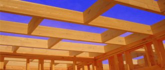
Wooden flooring is inferior in strength and rigidity to reinforced concrete, so it is installed in residential buildings up to four floors. Beams are made from coniferous wood (pine, spruce, fir, etc.). The length of the beams is most often 5–6.5 m. In stone buildings, the beams are laid at a distance (along the axis) that is a multiple of the size of the brick or blocks.
1. Blind seal. 2. Open termination. 3. Butt connection of beams. 4. Connecting beams staggered. a - brick wall, b - beam, c - internal support, d - metal overlay e - waterproofing
Beams are embedded in external stone walls using a blind and open method. Regardless of the method of sealing, it is necessary to take measures to prevent condensation of air vapor in the wall cavities. This occurs when their thickness is less than two bricks. In thicker walls, condensation does not form in the sockets.
The depth of the socket for supporting a beam in stone buildings, based on the compressive strength of the masonry, is taken to be 0.6–0.8 h (h is the height of the beam). The minimum permissible support size is 150 mm. Usually it is taken 180–200 mm. In this case, the beam should not reach the wall by 3–6 cm in order to ensure air access to its end.
The floor beams are impregnated with antiseptic compounds, and the end is necessarily insulated with two layers of waterproofing (tar paper, glassine). The space between the wall and the side surface of the beam is filled with mortar.
Every third beam must be connected with an anchor to the outer wall. The anchor is embedded at one end into the wall, and the arced end is attached to the beam. They are also connected to each other when supported on the internal walls.
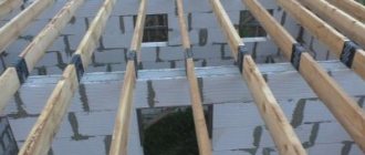
The subfloor is laid in two ways:
- Shields or boards are laid on the skull blocks using overlay strips.
- Continuous laying of shields (boards) directly on the skull blocks.
Beams and logs are lined from below with boards made of thin boards, gypsum plasterboard, gypsum fiber board, OSB or other sheet materials. Membrane insulation is laid, on which a heat and sound insulating layer is laid. This can be bulk, slab or roll insulation placed between the beams.
1. Floor beams. 2. Binder. 3. Subfloor. 4. Insulation 5. Vapor barrier
A vapor barrier layer is also placed on the thermal insulation. Next, a clean floor is installed, which can be attached to the joists or directly to the beams. The logs are laid on the floor beams. A gap is left between the insulation and the upper edge of the beams to allow air access to the wooden floor structures.
Determining the cross-sectional dimensions of a wooden beam using formulas
More often, the load-bearing elements of an interfloor or attic floor are beams with one span and free support on a load-bearing wall or pillar.
1. Round log. 2. Beam with two edges. 3. Beam, four edges. 4. Composite beam. 5. LVL timber. 6. Nascor beam 7. Board
They absorb bending from the weight of the entire floor and temporary payload (furniture, people, etc.). The required dimensions of the beam are determined by calculation. The condition for this is the specified strength and rigidity of the load-bearing element.
To determine the loads on the beam, the density of coniferous wood for the structures of premises with normal operating conditions is assumed to be 500 kg/m 3 . For wet rooms and outdoor structures - 600 kg/m3.
The tensile strength of coniferous wood working in bending is 75 MPa. The rigidity index (elastic modulus E) determines its ability to deform under the action of any loads.
For normal operating conditions of structures under loads:
- E = 10,000 MPa - along the fibers;
- across the fibers, the E index decreases almost 50 times.
Temperature also affects the reliability of wood. If it increases, the tensile strength and elastic modulus decrease. This increases the fragility of wooden products. The same thing happens when exposed to negative temperatures.
To calculate any structure, standard and design loads are determined. The design load is obtained by multiplying the value of the standard load by n - the reliability factor (overload), which takes into account the conditions under which the structure operates.
The strength of the beam is checked by the action of the maximum bending moment:
- σ is the stress in the beam;
- Wр - design moment of resistance;
- Ri is the calculated bending resistance, which for coniferous wood is 13 MPa.
The selection of the cross-section is calculated based on the required moment of resistance Wtr:
For a rectangular section:
For round sections:
Stiffness is checked against standard loads:
- f is the maximum deflection of the beam;
- l is the design span of the beam in cm;
- f/l - relative deflection, which should not exceed: 1/250 - for floors between floors; 1/200 - for attic floors;
- J is the moment of inertia in cm 4;
- q n - standard load in kg/linear. cm;
- E = 10,000 MPa, 100,000 kg/cm 2 - elastic modulus of wood;
- c is the maximum permissible coefficient for the ratio l/h, where h is the height of the beam section: 18.4 - for interfloor ceilings; 23.0 - for attic floors.
In the case where l ≤ ch, beams are checked only for strength. If l > ch, they are checked only for rigidity.
For example, let’s calculate a wooden beam for an interfloor floor. Span l = 4.5 m; floor weight - g = 200 kg/m2; temporary load p = 150 kg/m2; the distance in plan between the axes of the beams is a = 0.9 m; beam material - pine Ri = 130kg/cm2; m operating condition coefficient is 1.0.
Design load for 1 linear line. m element:
q = (g n n + p n1) · a = (200 ∙ 1.1 + 150 ∙ 1.4) ∙ 0.9 = 387 kg/linear. m
- n, n1 — reliability coefficients of permanent and temporary payloads.
The moment of resistance that is required is determined from the strength condition:
Table of moments of resistance W in cm 3 rectangular sections
| b | h | ||||||
| 8 | 9 | 10 | 11 | 12 | 13 | 14 | |
| 21 | 588 | 661 | 735 | 808 | 882 | 955 | 1029 |
| 22 | 645 | 726 | 807 | 887 | 968 | 1049 | 1129 |
| 23 | 705 | 793 | 882 | 970 | 1058 | 1146 | 1234 |
| 24 | 768 | 864 | 960 | 1056 | 1152 | 1248 | 1344 |
| 25 | 833 | 937 | 1041 | 1146 | 1250 | 1354 | 1458 |
| 26 | 901 | 1014 | 1127 | 1239 | 1352 | 1465 | 1577 |
Using specially calculated tables, you can select the rectangular cross-section of the element - bxh. We accept timber 8x24 cm (W = 768 cm 3). In the case under consideration, the ratio l/h = 450: 24 = 18.75, and the maximum permissible c = 18.4 for interfloor ceilings. Based on this, deflection calculations are not performed.