The essence of the phenomenon
Unlike natural resources like gas, electricity cannot be pumped into storage facilities and taken from there as much as needed. Therefore, electricity generation directly depends on consumption. When there is more demand for electricity, the power plant produces more electricity.
Daily use of electricity
Thus, the transmission of electric current can be characterized as a continuous process of generation, transportation and consumption. At the state level, the transmission of electricity is a matter of strategic security and is a priority task, for the infrastructure of which huge amounts of budget funds are allocated annually.
For example, in Russia in 2021, $30 billion was spent on improving energy infrastructure.
Additional Information . Recently, the world's first Tesla electric storage station was launched in Australia. The electricity itself is produced by wind turbines, which charge a giant bank of batteries. From them, energy is already transferred to the end consumer via wires. This way, people are not left without electricity on a windless day.
Solving the problem of wind turbines by accumulating electricity
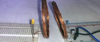
Wireless power transmission, first experiments
In 1888, Heinrich Hertz experimentally confirmed the existence of electromagnetic waves predicted by Maxwell. His spark transmitter with a Ruhmkorff coil chopper could produce electromagnetic waves up to 0.5 gigahertz. Which could be received by several receivers tuned in resonance with the transmitter.
Heinrich Hertz and his creation
Receivers could be located at a distance of up to 3 meters, and if a spark occurred in the transmitter, sparks occurred in the receivers. This is how the first experiments were carried out on wireless transmission of electrical energy using electromagnetic waves.
In 1891, Nikola Tesla, while researching alternating currents of high voltage and high frequency, came to the conclusion that it is extremely important for specific purposes to select both the wavelength and the operating voltage of the transmitter, and it is not at all necessary to make the frequency too high. The scientist notes that the lower limit of frequencies and voltages at which he was able to achieve the best results at that time was from 15,000 to 20,000 vibrations per second with a potential of 20,000 volts
We advise you to study Load Break Switch
Nikola Tesla
Tesla obtained high frequency and high voltage current using an oscillatory discharge of a capacitor. He noted that this type of electrical transmitter is suitable both for producing light and for transmitting electricity to produce light.
In the period from 1891 to 1894, the scientist repeatedly demonstrated wireless transmission and the glow of vacuum tubes in a high-frequency electrostatic field. At the same time, noting that the energy of the electrostatic field is absorbed by the lamp, converted into light. And the energy of the electromagnetic field used for electromagnetic induction to obtain a similar result is mainly reflected, and only a small fraction of it is converted into light. Even using resonance when transmitting using an electromagnetic wave, it will not be possible to transmit a significant amount of electrical energy, the scientist argued. His goal during this period of work was to transmit precisely large amounts of electrical energy wirelessly.
Until 1897, in parallel with Tesla's work, research on electromagnetic waves was carried out by: Jagdish Bose in India, Alexander Popov in Russia, and Guglielmo Marconi in Italy.
Following Tesla's public lectures, Jagdish Bose gave a demonstration of wireless transmission of electricity in November 1894 in Calcutta, where he ignited gunpowder, transmitting electrical energy over a distance.
After Boche, namely on April 25, 1895, Alexander Popov, using Morse code, transmitted the first radio message, and this date (May 7, new style) is now celebrated annually in Russia as “Radio Day.”
In 1896, Marconi, having arrived in Great Britain, demonstrated his apparatus, using Morse code to transmit a signal over a distance of 1.5 kilometers from the roof of the Post Office building in London to another building. After that, he improved his invention and managed to transmit a signal across the Salisbury Plain over a distance of 3 kilometers.
Receipt and transmission
To begin with, it is worth touching on the topic of obtaining energy. Over the past 150 years, humanity has made huge strides in developing ways to produce electricity. Today, non-renewable sources are used, for example, the combustion of coal and gas, and renewable ones - the movement of water and wind.
The best minds on the planet are working to improve renewable production technologies, in other words, environmentally friendly sources. After all, energy consumption is growing every year and power plants have to burn more and more coal and gas, thereby depleting natural reserves and harming the environment. Another thing is a wind turbine or hydroelectric power station, for which wind and water will never run out. But their efficiency is still extremely low.
Types of power plants
Since in most CIS countries the main supplier of electricity to homes is local thermal power plants (Thermal power plants powered by coal, oil or gas), it is necessary to consider the process of obtaining it using their example.
You might be interested in Features of Fuquay eddy currents
Scheme of energy production from the combustion of minerals at thermal power plants
As you can see, the process occurs as follows:
- Coal and air are supplied to the firebox.
- The heat from the firebox heats the water and turns it into steam.
- Pressurized steam is supplied to the turbine.
- A powerful flow of steam causes the turbine to rotate.
- Together with the turbine, the generator rotor begins to rotate, which already converts mechanical movement into electricity.
The ultimate meaning of any ES, no matter what sources it operates on, is to rotate the turbine. At thermal stations, the turbine is rotated by steam, at hydroelectric power stations it is water, and in a wind turbine it is wind.
Due to the high cost, it is impossible to build a power plant in every city. In fact, most stations provide electricity to one large metropolis and hundreds of surrounding villages, hamlets and urban settlements.
Before reaching a populated area, the extracted energy travels tens or even hundreds of kilometers. Here it is worth talking about how current generally travels through wires.
After leaving the station generator, the electric current enters a transformer to increase the voltage to 1150 kV. Why is this being done? The higher the voltage, the less electricity loses its power as it travels through the cable. But what is also important is the cost of transmitting electricity. The higher the voltage, the smaller the wire cross-section is needed. The thinner the cable, the less conductive metal it contains. The less metal, the cheaper it is.
High voltage power lines
However, there is also some electrical dissipation effect. While the current travels a hundred kilometers, it will inevitably lose some of its power. Also, the decrease in efficiency depends on the resistance force of the metal in the cable.
Additional Information. Scientists are considering eliminating wires from the electricity transmission chain.
For this it is planned to use the familiar Wi-Fi technology.
Schematic diagram of the supply and distribution of electrical energy
Control of the distribution of electricity and its transmission from source to receiver of the third category within the city is most easily accomplished using a radial dead-end circuit.
However, such a circuit has one significant drawback, which is that if any one element of the system fails, all receivers connected to such a circuit will be left without power. This will continue until the damaged section of the chain is replaced. Due to this drawback, it is not recommended to use such a connection scheme.
If we talk about the connection and energy distribution diagram for receivers of the second and third categories, then here you can use a ring circuit diagram.
With this connection, if there is a failure in the operation of one of the power lines, you can restore the power supply to all receivers connected to such a network manually by turning off the power from the main source and starting the backup one. The ring circuit differs from the radial circuit in that it has special sections in which disconnectors or switches are located in the off mode. If the main power source is damaged, they can be turned on to restore supply, but from the backup line.
This will also serve as a good advantage if any repair work needs to be carried out on the main line. A break in the power supply to such a line is allowed for a period of about two hours. This time is enough to turn off the damaged main power source and connect the backup one to the network so that it distributes electricity.
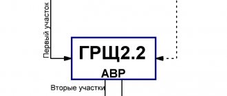
There is an even more reliable way to connect and distribute energy - this is a circuit with parallel connection of two supply lines or the introduction of automatic connection of a backup source.
With such a scheme, the damaged line will be disconnected from the general distribution system using two switches located at each end of the line. In this case, the supply of electricity will be carried out in a still uninterrupted mode, but through the second line. This scheme is relevant for receivers of the second category.
Power lines
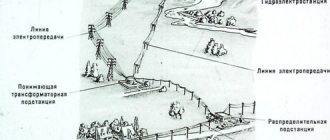
Here it is worth talking about what networks are used to transmit electricity. From the power plant to the end consumer, electricity passes not only through a step-up transformer and high-voltage lines. If you look at a modern city from above, you will notice a whole tangle of wires forming a single network.
To get to the consumer, the current from the high-voltage lines re-enters the transformer, but this time the voltage is reduced. After which it is supplied to the distribution network and distributed to industrial enterprises, which have their own substation to receive the voltage they need, to city substations, which distribute electricity through main cables, and to regional substations.
You might be interested in: Features of a two-zone meter
City substation
From regional substations through power lines, electricity is supplied to private, apartment buildings and infrastructure facilities. In residential neighborhoods, cables from substations are mostly laid underground, from where they go out to the entrance panel, which then distributes the current to every socket and light bulb in the house.
Power box of a high-rise building
Microwave
Microwaves are special lines with a length of 12 centimeters and a frequency of 2.45 gigahertz, which are transparent to the atmosphere. Regardless of the weather, the energy loss will be 5%. First, it is necessary to convert the electric current into microwaves, then detect them and return them to the first state. The first problem was solved thanks to the installation of a magnetron, and the second - thanks to a rectenna or a special antenna.
You may be interested in this All about electricity
Microwave energy transfer
Transmission schemes
At first glance, the complete scheme for transmitting electricity from a rotating turbine to an apartment socket may seem complex and confusing, but if you look at the diagram, everything falls into place.
Block diagram of power supply
It is worth noting that if there are no industrial enterprises in the city, then in reality there will not be a substation for an industrial facility and the entire branch presented for it. All other electrical infrastructure will be present before wireless transmission is invented.
In the above diagram you can see the main cable lines. They can be of two types - single and double-sided. Double-sided ones are more common today, since single-sided ones are less reliable, plus it’s difficult to find the place of damage on them. Thus, the end user is always supplied with electricity, and breakdowns on the main lines are invisible to him.
Two-way highway diagram
Electricity is produced by using renewable and non-renewable energy sources to spin a turbine. The turbine drives the generator rotor, which generates electricity. To transmit current, the transformer increases its voltage, and before sending it to the city network, the voltage is reduced back. This reduces losses and network construction costs. After this, electricity is supplied to the city substation, which powers regional substations, and branched lines are laid from them to end consumers.
Long-distance power transmission methods
The transmission of electrical energy can be done through direct transmission and conversion of electricity into other energy. In the first case, electricity flows through conductive elements, namely a wire or conductive medium. Overhead or cable lines use this method of power transmission.
You may be interested in this: How to calculate grounding
Note! By converting energy into other energy, a wireless method of supplying consumers is opening up. Because of this, users can eliminate electrical transmission and eliminate installation and maintenance.
It is also worth pointing out that electricity is transmitted due to inductive, resonant inductive, capacitive, magnetodynamic coupling, microwave radiation and optical radiation. In this case, the carrier of all these methods is the magnetic and electric field, as well as visible light with infrared radiation and ultraviolet radiation.
Power transmission methods
Electricity transportation route
So, as we have already said, the starting point is the power station, which, in fact, generates electricity. Today, the main types of power plants are hydro (hydroelectric power plants), thermal power plants (thermal power plants) and nuclear power plants (nuclear power plants). In addition, there are solar, wind and geothermal electricity. stations.
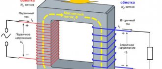
Next, electricity is transmitted from the source to consumers, who may be located over long distances. To transmit electricity, you need to increase the voltage using step-up transformers (the voltage can be increased up to 1150 kV, depending on the distance).
Why is electricity transmitted at increased voltage? Everything is very simple. Let's remember the formula for electrical power - P=UI, then if you transfer energy to the consumer, then the higher the voltage on the power line, the less current in the wires, with the same power consumption. Thanks to this, it is possible to build power lines with high voltage, reducing the cross-section of the wires, compared to power lines with lower voltage. This means that construction costs will be reduced - the thinner the wires, the cheaper they are.
Accordingly, electricity is transferred from the station to a step-up transformer (if necessary), and after that, with the help of power lines, electricity is transferred to the central distribution substations (central distribution substations). The latter, in turn, are located in cities or close to them. At the central distribution point, the voltage is reduced to 220 or 110 kV, from where the electricity is transmitted to substations.
Next, the voltage is reduced again (to 6-10 kV) and the electrical energy is distributed among transformer points, also called transformer substations. Electricity can be transmitted to transformer points not via power lines, but by an underground cable line, because in urban environments this will be more appropriate. The fact is that the cost of rights-of-way in cities is quite high and it will be more profitable to dig a trench and lay a cable in it than to take up space on the surface.
From transformer points, electricity is transmitted to multi-story buildings, private sector buildings, garage cooperatives, etc. We draw your attention to the fact that at the transformer substation the voltage is reduced once again, to the usual 0.4 kV (380 volt network).
If we briefly consider the route for transmitting electricity from the source to consumers, it looks like this: power plant (for example, 10 kV) - step-up transformer substation (from 110 to 1150 kV) - power lines - step-down transformer substation - transformer substation (10-0.4 kV) – residential buildings.
This is how electricity is transmitted through wires to our home. As you can see, the scheme for transmitting and distributing electricity to consumers is not too complicated, it all depends on how long the distance is.
You can clearly see how electrical energy enters cities and reaches the residential sector in the picture below:
Experts talk about this issue in more detail:
How electricity moves from source to consumer
Real projects today
In all recent years, according to the above technologies, scientists have tried and are trying to implement only two projects.
The first of them started out very encouragingly. In the 2000s, on Reunion Island, a need arose for the constant transmission of 10 kW of power over a distance of 1 km.
The mountainous terrain and local vegetation did not allow the laying of overhead power lines or cables there.
All movements on the island to this point were carried out exclusively by helicopters.
To solve the problem, the best minds from different countries were gathered into one team. Including those previously mentioned in the article, our scientists from Moscow State University V. Vanke and V. Savin.
However, at the moment when the practical implementation and construction of energy transmitters and receivers should have begun, the project was frozen and stopped. And with the onset of the crisis in 2008, they completely abandoned it.
In fact, this is very disappointing, since the theoretical work done there was colossal and worthy of implementation.
The second project looks crazier than the first. However, real funds are allocated for it. The idea itself was expressed back in 1968 by US physicist P. Glaser.
He proposed an idea that was not entirely normal at that time - to launch a huge satellite into geostationary orbit 36,000 km above the earth. Place solar panels on it that will collect free energy from the sun.
Then all this should be converted into a beam of microwave waves and transmitted to the ground.
A sort of “death star” in our earthly realities.
On the ground, the beam must be caught by giant antennas and converted into electricity.
How big do these antennas need to be? Imagine that if the satellite is 1 km in diameter, then the receiver on the ground should be 5 times larger - 5 km (the size of the Garden Ring).
But size is only a small part of the problem. After all the calculations, it turned out that such a satellite would generate electricity with a capacity of 5 GW. When reaching the ground there would be only 2GW left. For example, the Krasnoyarsk hydroelectric power station produces 6 GW.
Therefore, his idea was considered, calculated and put aside, since everything initially came down to price. The cost of the space project in those days reached $1 trillion.
But science, fortunately, does not stand still. Technologies are improving and becoming cheaper. Several countries are already developing such a solar space station. Although at the beginning of the twentieth century, only one brilliant person was enough for wireless transmission of electricity.
We advise you to study Direct and Alternating Current
The total price of the project dropped from the original to $25 billion. The question remains - will we see its implementation in the near future?
Unfortunately, no one will give you a clear answer. Bets are placed only on the second half of this century. Therefore, for now, let's be content with wireless chargers for smartphones and hope that scientists will be able to increase their efficiency. Well, or in the end, a second Nikola Tesla will be born on Earth.