How it all began?
What is CB? This designation is used as an abbreviation for the English phrase "civil band". It is adopted to designate accessible and license-free radio communications on short waves, occupying the 27 MHz band. Depending on the country, there may be minimal or no regulations governing its use. Radio communications can be portable, portable or stationary. They differ from professional stations (and a large number of amateur ones) in price and number of available functions. The simplest versions of this band can only receive and transmit audio information over relatively short distances over rough and wooded terrain. You can work to eliminate natural interference or focus on increasing the coverage distance. But let's not rush yet.
Testing
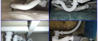
Small tests have been done. There were two Baofeng UV-5R transceivers in the HT and BF-666 versions. Check on channel 4 PMR. BF-666 was on the 4th floor of the house while moving down the street with UV-5R. Range tested and recorded at 3 different distances in urban areas with medium-height buildings.
- Very good connection on both sides on both antennas.
- The UV-5R radio received and transmitted very well, when it comes to the BF-666 base on the new antenna, on the standard short one the signal was often interrupted and weakened during reception and transmission. The advantage of a homemade quarter-wave antenna is obvious.
- It was no longer possible to communicate even with a GP antenna. The base did not receive anything from the UV-5R at all; only snippets from the BF-666 were heard on the street.
It should be noted that the setup process is completely skipped due to the lack of a wave meter. The antenna, as you know, must be tuned by trimming. To do this you will need an SWR meter, which is quite expensive for this range. Unless you assemble such a simple device:
Where are they used?
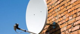
CB radios have a fairly wide range of applications. They are quite reliable and affordable means of communication that allow interaction between the store and the warehouse, trucks, and so on. CB radios are also used on small fleets - boats and yachts. At the same time, the operating range on water increases significantly due to the fact that there are no serious obstacles.
The greatest use of the CB range was found by representatives of mobile communications. An example is devices installed in cars. With portable devices it is a little more difficult. The fact is that the CB range has a wavelength of 11 meters. And the ideal antenna for it should be about 2.7 m in size. On portable devices they have to be shortened by 10-20 times. The result is a fairly large weight, low efficiency when transmitting data to a compact antenna, and low amplitude noise reduction efficiency. But thanks to the fairly significant CB wavelength, the antenna can operate even in the presence of significant obstacles. It is well suited for rough terrain and forests.
Step-by-step setup instructions
The radio antenna should be configured according to the following algorithm:
- For correct settings, you must have a device such as an SWR meter.
- The setup process must be done away from structures made of metal, concrete or wood. It is advisable that trees be placed no closer than 15-20 m.
- It is highly advisable to stop the car on a clean, level and dry surface.
- Antenna tuning may also be affected by nearby vehicles with radio antennas. Next, you need to install the SWR meter according to the instructions, that is, between the radio itself and the antenna. In this case, you cannot use an amplifier.
- Measurements with the device must be made on several different channels and at different points. It is advisable to carry out this procedure in different grids. This will allow you to see the real picture of the settings.
- The next step is very important: you should find the minimum SWR indicator, ideally the indicator should be equal to 1, it is advisable to write down where it is located. If it is located at a frequency below the specified one, this means that the antenna needs to be shortened. Accordingly, if it is higher, you need to lengthen it.
- The next step is to shorten or lengthen the antenna, depending on the SWR readings of the device. Lengthening or shortening is the process of adding or, conversely, unwinding turns from the matching coil, and not shortening the antenna with wire cutters.
- After this, you again need to look at the SWR meter. Repeat the procedure until the desired result is achieved. Sometimes in some models it is not possible to achieve the ideal indicator, but this is not a big deal. If the indicator deviates, for example to 1.5, the losses will be equal to 5%. The walkie-talkie will work quite normally even with an indicator of 3. If an amplifier is built into the system, you need to take into account that the minimum indicator should not exceed 2.
If all steps of the algorithm are completed correctly, the antenna for the radio in the car will serve perfectly.
Helpful information
The CB radio station allows you to contact the police, ambulance, fire department and emergency services thanks to special dispatchers. It should be noted that such an opportunity is not always available. Channel 9C is allocated for this purpose. But, alas, in practice this can only be found in Moscow and St. Petersburg. In the rest of the territory, it is better to use channel 15C, through which you can establish communication with drivers on the highways. Additionally, on 19C you can find radio amateurs. You can appeal to all these people for help. The main thing is that there would be enough power to send and receive a response signal. Now let's look at how to make an antenna with your own hands.
Making a radio antenna
Let us briefly recall the process of manufacturing an antenna for a walkie-talkie. We considered digital television, WiFi, 3G. The audience of the VashTekhnik portal knows how to make an antenna for a walkie-talkie. Feel free to copy the methods. First you need to know the frequency. More precisely - better. The radios have several channels, the frequencies are registered in the passport. Select a channel by specifying the antenna dimensions.
Let the frequency be 435 MHz. We find the wavelength using the school formula, dividing the speed of light by the indicated value: 299792458 / 435000000 = 689 mm. To make a quarter-wave vibrator, you need to divide the number by another 4, we get - 172.25. The length of the antenna for the walkie-talkie will be 17 cm. Try to keep the millimeters more accurately. The screen does not need to be cleaned. It will be a receiving surface, the band will increase. If your hands are itchy, peel off the braid and leave the dielectric around the main core.
The old antenna is desoldered, a clamp is ready for the new one. All that remains is to fix it in place, enjoy the connection. The antenna for the walkie-talkie is made by hand. By the way, if you don’t want to remove the screen, solder it together with the core in one bundle when mounting it on the chip. If you consider expanding the range unnecessary, it’s better to remove the screen. The first and second options have advantages; the solid cable is stronger. It's better to leave it as is. The radio antenna will last longer. Make sure to glue on a nice cap-tip so that the copper stops oxidizing. We say goodbye until next time.
Copy factory designs. Enterprise radios break down. The adapters remain, the devices are thrown away. An invaluable chance for a radio amateur to prove himself. The antenna is covered with rubber, which can be easily peeled off. Or use an accessory from a broken product. The process of copying is not directly prohibited, except for products protected by patents. The case concerns the industrial production of products for the purpose of marketing, obtaining a fixed profit by performing the specified actions.
Theoretical preparation
So, for our homemade product there are a number of requirements:
- It must at least partially provide protection from atmospheric and industrial interference.
- It is necessary to take care of the “ground” for normal signal reception.
- To transmit data to the antenna, it must be tuned.
If we talk about the design, there are two main options: horizontal and vertical design. Each of them has its own characteristics. To find the optimal solution, the antenna is often placed at a 45 degree position. Vertical execution is considered more complex, but also better. It requires higher resistance than horizontal. In addition, the latter option is more dependent on the distance to the ground - the further it is, the higher the resistance. To meet different design requirements, several possible designs will be considered. If desired, without complicating everything too much, they can be improved. So, how to make an antenna with your own hands?
Very simple option
We will make it from scrap materials. From the purchased ones - only UNF connectors and RG-58 cable. The antenna surface will be equal to the wavelength. By adjusting it to resonance, it can be shortened and made a little longer. If the transmitter is coaxial, then the power supply must be balanced. The easiest way is to use low-frequency ferrite (from 400 to 2000 NN). When creating a CB antenna with your own hands, a transformer from a computer power supply can play its role. It should be noted that standard yellow rings will not fit, so two turns of cable must be wound around the core. And here one question becomes relevant. Namely, which antenna cable to choose? Let's assume that we need an optimal solution in the price/quality coordinate system. In this case, you can pay attention to a regular piece of wire ShVVP 2X0.75. It is divided into two conductors, which are soldered together. The total length should be eleven meters. At the same time, maintaining equality of arms is not a critical point. As an insulator, you can use a plastic ring - for example, from a baby rattle.
Rapid deployment antenna on CB (27.200)
The authorship of the antenna design belongs to RX3AKT. In essence, this antenna is a half-wave vibrator powered from the end and matched with a cable loop. In terms of efficiency, such a coaxial antenna is not much inferior to factory analogues from the same Sirio, and is much simpler and more compact to manufacture. The antenna was conceived as a traveling option, since it is very light and compact, but it can also be used stationary.
What you need to make a rapid deployment antenna
For manufacturing you will need 7 meters of RG-58 cable (antenna fabric + matching part), a piece of RG-58 cable of arbitrary length to connect the antenna to the walkie-talkie, a PL-259 or SO-239 connector, a few centimeters of heat shrink of a suitable diameter (for example 7mm and 12mm), instant glue, a sharp knife, a soldering iron with solder and rosin, and 40 minutes of free time. For modeling, I recommend using the crappiest cable on the market, namely REXANT. These guys make great solder and other radio mounting stuff, but their cable is truly terrible, but it is cheap and can be used for antenna building experiments.
Antenna design
The antenna consists of 3 parts. The part is 520 cm long; this antenna sheet is the radiating part. The part 152 cm long is the matching part, it represents a capacitance, the part 23-24 cm long also belongs to the matching part and represents inductance. During the assembly process, it is easiest to use the image from the title of the article. The points in the figure are solder joints.
1. Take the RG-58 cable and cut a piece 7 meters long.
2. Strip the braid on the cable from both ends, approximately 1-1.5 cm.
3. Remove the foil, if any, and twist the central core with the cable screen.
4. Carefully solder the twist of the central core and screen.
5. Next, measure 23 cm from one of the ends of the cable and make a cut in the cable braid, but so as not to damage the screen. We retreat another 2 centimeters (25cm) from the cut and make another cut. Our task is to remove the PVC cable braid without damaging what is underneath it.
We remove the braid and foil, and move the screen to one side and cut it in half. Let's leave it alone for now, we'll come back to this later.
6. We measure 152 cm from the area with the braid removed, and just as in point 5, cut off a part of the braid about 1.5-2 cm wide from the cable. After this, cut the screen from the short part (23 cm + 152 cm) so that on the short part the screen protruded beyond the braid minimally. Remove the foil.
7. Using a sharp knife, remove half of the polyethylene protecting the central core, so as not to damage it and not completely cut the fabric in half. We tin the central core and the screen and solder them to each other.
8. After the soldering area has cooled and the polyethylene has hardened, you need to seal the connection. To do this we use Moment glue. Coat the connection generously, especially the soldering area and the cut ends of the braid. But without fanaticism. Be sure to let the glue dry a little and only then move on to the next step.
9. We put a heat-shrinkable tube with a diameter of 6-7 mm on top and shrink it (best by heating it with a hairdryer). On top, you can apply another layer of heat shrink, so to speak, for strength and greater length. After the glue cools and dries, a completely strong and airtight connection is obtained.
10. Return to the 23 cm piece. Similarly to point 7, remove the layer of polyethylene up to the central core and solder the reduction cable. It must first be cleaned, as in point 2. Solder the central core of the reduction cable to the central core at the point 24 cm.
11. We put heat shrink with a diameter of 8-10 mm on top and place it on both central cores.
12. We solder the screens of part of the 23 cm cable, part of the 152 cm cable and the reduction cable at one point.
13. Coat the soldering area generously with glue, let it dry and put heat shrink with a diameter of 12mm on top. We sit down.
14. On the ends of the antenna (23 cm and the radiating part), also coated with moment, we put trem-shrink on it and seat and seal the ends.
15. Solder the connector for the radio station to the end of the reduction cable and... Done.
Field tests
In progress…
Good luck to everyone, 55, 73!
Dipole radio
A CB antenna of this type can be easily made with your own hands. After all, the dipole is considered very simple to learn and implement. It is possible to create a device suitable for long-term maintenance-free operation. In addition, it can work well in less than favorable conditions. What is a dipole? In fact, this is the simplest and at the same time the most common antenna, presented in the form of a symmetrical vibrator. The simplest implementation option is a straight conductor, the length of which is equal to half a wave, powered by high-frequency currents from a generator. In simple words, they take two identical pieces of wire and stretch them sequentially in space. A cable is connected in the center of this structure, from which the signal is transmitted from the dipole to the transceiver and back.
A DIY CB antenna can be made vertically or horizontally. The first option is more suitable for establishing local communications, and the second – long-distance. If the dipole is at an angle, then both possibilities are available.
Installation and connection
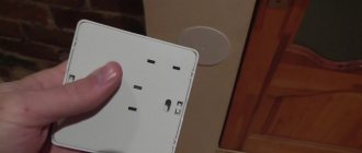
To check the operation of the antenna, connect the free end of the cable to the receiving and transmitting device. This could be a small walkie-talkie like BAOFENG. It is better to check before the device is installed in the case.
To minimize losses during signal transmission, use the shortest and thickest cable possible. It is connected using a connector. To do this, put on a 10 cm long heat-shrink tube, a ring and the connector itself, which needs to be strengthened with a crimper.
Determine the placement of the antenna. The device can be installed on a wall or roof of a house, on a mobile device, etc. If necessary, we fix a metal corner there. We fix the manufactured structure with clamps to the selected location. We connect the cable to the transmitting/receiving device.
Designing a dipole
Before we start doing anything, we need to calculate what we need. It should be understood that the geometric length of the dipole will be slightly less than that calculated by the formula. Why? This is due to the process of the appearance of capacitive current at the ends of the antenna, which is equivalent to an increase in its length. The exact length of the dipole (which takes into account the shortening factor) can be calculated using formulas that will not be given here, since technological tools in the form of modeling programs can be used to achieve this goal. MMANA was used as such. So, it turns out that the top point should be at a height of three meters, the center - 2.5, and the bottom - 2 m. The length of the arms is 2.57 m, the wire chosen to create the antenna has a diameter of 2 millimeters. This design has a resistance of approximately 75 ohms. This is equivalent to SWR=1.5. You can select a balancing device to power the antenna. It is essentially a balun transformer. Why this way, and not, say, through a coaxial cable? The fact is that a dipole is a symmetrical antenna. And it will not be able to be powered by the cable, because it is an asymmetrical line.
Comparison of different types of devices
Each type of device has its own disadvantages and advantages. The required type of receiving and transmitting device is selected depending on the priority and nature of use.
The largest dimensions are for a whip antenna. However, it has a long range, so it is used where this indicator is the most important - in television, radio stations, telephones, car receivers, etc. The disadvantage of these systems is their strong dependence on the external environment. The close proximity of surrounding surfaces, poor weather conditions, etc. have a negative impact on them.
Helical antennas are even more susceptible to external influences, but their size is smaller than that of whip antennas. Due to this, they can be used as a compromise solution in a home controller, gate opener and similar devices.
Loop antennas are small in size. Their range of action is less than that of the previously discussed types of devices. However, their advantage is independence from external factors. Mainly used in transmitters.
Assembling the antenna
So, to create we need:
- Plumbing plastic coupling. Suitable with a diameter of 50-55 centimeters.
- SO-239 connector.
- Plumbing plugs commensurate with the previously selected coupling.
- Three ring screws.
- Three nuts and six washers.
In the coupling, we make a plug for fastening of 6 millimeters and for the connector of 16 mm. The balun can then be connected or assembled. We will imagine that we don’t want to buy. Therefore, we take a ferrite ring with a permeability of 600, a piece of wire with a cross-section of 0.5-1 mm. We fold the wire in three and begin to wind it around the ring. After a full-fledged CB antenna coil is ready, the winding is fixed using insulating tape or clamps. We mount the balloon into the blank, and then solder the connector. The structure is almost ready. It remains to measure the required number of wires for the best antenna in order to secure them to the workpiece. Thickness doesn't matter here. As an example, you can take three meters of 1.5 mm. By the way, although the program calculated that the optimal value is 2.57, it is better to take a little with a reserve. That's why it's three meters. We solder everything - and our antenna is ready.
For auto
A modern vehicle must have a radio or even something more. Navigation, television and radio communications are not a complete list. But very often you have to buy something you want yourself. Or do it. For example, a do-it-yourself car antenna for radio communication. How to implement this? Regular antennas will not work. Why? The fact is that vehicles often move during communication sessions. And traditional antennas in this case will have a certain “dead” reception zone. Even if you drive in such a way as to prevent this from happening, disconnections still occur during maneuvering.
To summarize, we can understand that a self-made car antenna must meet the following requirements:
- Have a high efficiency (after all, CB is needed not only to listen, but also to transmit information).
- Ensure reliable operation at the selected frequency.
- Fits in the cabin.
- Do not raise questions from traffic cops regarding modifications to the hulls.
Specifics of car antennas
The quarter-wave transmitter can be discarded outright - it is too big. In this case, our CB radio station will not satisfy with its size. But if the machine has a frame structure, then you can take advantage of its advantages. In order to tune the antenna into resonance with the required frequency, a capacitor is used. But what to do with the length? One of the most popular solutions is the design of the antenna in the form of a spiral. Another method that is no less popular is to make an antenna in the form of a trapezoid. In this case, it is recommended that the length of the CB antenna be as follows: top edge - 56.5 cm, bottom base - 66.5 cm, sides - 22.5 cm + 45 cm for connection. As you can see, having made not very significant changes to the design, we were able to get the same thing that was needed before. But the trapezoidal antenna easily fits into the car. Overall, there is a lot of room for thought here.
DIY car antenna
Car antennas today differ in purpose. In combat conditions they receive communications, in peaceful conditions they receive broadcasting channels and navigation information. The car antenna is a quarter-wave vibrator, supplemented with matching devices. The signal line, the ground, will be the body of the car. Due to these two components, signal reception becomes possible. Due to the simplicity of the design, they make a car antenna with their own hands. First determine the purpose of the device, wave range, and modulation type. Three main components laid down by the design.
Types of car antennas
We mentioned the types of car antennas, but here is a redundant classification:
- Radio reception.
- TV reception.
- Reception of satellite information from navigation systems.
- Communication car antennas.
- Method of installing antennas on a car:
- Magnetic.
- On a suction cup.
- Mortise.
- Threaded connection.
- On a clamp.
- Built-in.
Connection diagram for a car antenna under the rear fender
- External car antennas.
- Salon (internal).
Surely an experienced car enthusiast will be able to add a couple of signs, but we will limit ourselves to the specified classification. FM antennas fit inside the cabin. Hobbyists make accessories with their own hands, using pieces of cable with a characteristic impedance of 50 Ohms. The braid is electrically connected to the car body (ground). Be careful of catching lightning while driving through a field. The thunderstorm chooses the point closest to the sky.
The size of the car antenna depends on the range. Communications (walkie-talkies with a frequency of 27 MHz) are large. Powerful varieties reach a length of 2 meters (they are placed on trucks); according to science, they should be made 50 cm higher. To reconcile the differences between the actual size, a quarter of the wavelength is an “extension” coil at the base. For use, the car antenna for communication is installed vertically. Determined by the type of polarization. The communication antenna can be tilted by means of a thumb or lever, so as not to break it when driving through a forest or overcoming the spans of a low bridge. Communication antennas are mostly used by drivers of large trucks. It is allowed to equip jeeps and civilian cars, but at times the appearance will be unsightly.
Note. Factory antennas are tuned to the wavelength. The mustache is shortened, equipped with a protective cap at the end. The operation is carried out according to the instructions. The guide includes a chart of recommended sizes. The violation causes a decrease in reception sensitivity.
Authorization kit
The digital car TV antenna looks like a police flasher and is made in a different color scheme. The device is devoid of unnecessary bells and whistles and accepts a frequency of hundreds of MHz. The first multiplex in Moscow chose 559 MHz. The digital car antenna on a magnet is placed on the top (roof), the wire passes over the door without any modifications. A horizontal polarization signal; the device’s task is to receive an arbitrary azimuth.
Broadcasting antennas are rarely boasted of being large, since the wavelength is higher and the dimensions are larger. Small height pins, like those decorating portable radios. Beware of accidentally buying a car radio antenna intended by the manufacturer to decorate a television receiver. For fear of making a mistake, read the technical specifications in the store:
- Radio is designated FM, AM (frequencies 70 - 108 MHz).
- Television - DVB - T (frequencies below 900 MHz).
- Navigation – GPS (about 400 MHz).
- Radio communication – SV (27 MHz).
Sometimes dealers forget to indicate the antenna capabilities. The range of 400 - 530 MHz is given, it is mentioned that “the option of receiving GPS signals is available.” One can only guess what the copy can do; the first Moscow multiplex passes by. Frequencies above 400 MHz are used by portable radios and departmental communications of the Ministry of Internal Affairs.
It remains to pay attention to the connector. It matches the vast majority of devices for which it is intended; it would be useful to check the compatibility issue. They say that an external car antenna provides better reception; the question concerns mainly urban reception. While racing along the highway, the windows of a typical passenger car will not create serious obstacles to the passage of electromagnetic radiation. Installation of interior car antennas is simpler. Accessories are lower than external ones, hence the worse quality.
The store will provide all sorts of hybrid models, including options a la All in One. You can switch reception from city to highway. It is distinguished by sensitivity and interference suppression features. The suburban reception range increases to 80 km. They sell unique tandems. A pair of similar looking pins are laid out, one of which picks up TV broadcasts, the other picks up radio and communications. Using the delights of the set requires the purchase of appropriate receiving equipment.
Making a car antenna with your own hands
The only difficulty is that the body of the car is constantly moving. Traditional terrestrial household antennas in this case will form reception dead zones. There will be long periods of time when maneuvering when there is no reception. Applies to horizontal polarization, not vertical! In the latter case, the antenna does not care about the azimuth of the signal arrival. The mast stands vertically! This was discussed by ordinary frame biquad antennas and quarter-wave vertical vibrators. Let's see what else is useful to nature.
Zeroing the braid using mass
How to make a car antenna with your own hands to:
- did not cause any complaints from the traffic police for excessive modification of the body;
- stood up in the cabin;
- ensured reliable reception of radio frequencies;
- had high efficiency (since you need to work on transmission).
A quarter-wave vibrator is not suitable for this case. Difficult to manufacture, equipped with relatively large dimensions (see above), difficult to attach, and interferes with driving. Here is an idea from drivers of VAZ 2106 cars (an experienced radio amateur will remake the concept, abstracting from the make of the car).
A frame structure is used, laid under the rear window seal of the car. Slightly narrowed at the top, slightly different in size than required by the 27 MHz frequency, there is a capacitor in the center, which is used to tune the car antenna to resonance on the desired channel. Please note that there are two receiving frequencies:
The upper resonance occurs in the lower range of radio broadcasting. The car antenna circuit is simple:
- It is necessary to line the perimeter of the rear window in a trapezoid with MGTF 0.5 wire:
- Top edge 56.5 + 56.5 cm.
- Bottom edge 66.5 + 66.5 cm.
- Sidewalls 22.5 + 22.5 and 45 cm.
The spiral section reduces the overall length of the antenna
- The pluses are where we will add the wires of the matching capacitor, we will remove the signal with the RK-50 cable.
- In the middle of the glass, two wires go vertically to the center, where a trimmer capacitor (5 - 25 pF) is attached exactly along the axis. Each one is 45 cm long. Therefore, you will have to twist it in a zigzag and place it under an insulating tube.
- We solder the cable from the side where the wire is cut in the middle. There should be no gap on the opposite side.
The car antenna is connected through the connector used by communication equipment. The cable length is short, or rather, you should take a shorter one. Since the antenna is passive, the signal will be greatly attenuated in the path to the receiver. If you really put connected equipment near the rear window, it’s worth doing.
Advantages of a homemade loop car antenna
See the advantage. It is unlikely that our DIY car antenna will have too long a range or show miracles of reception, but it is competitive with some factory models that are mounted on the roof and have a height greater than that of a passenger car. Plus, in the forest, the city won't hurt. In addition, there is no need to wind the matching device. This is not easy; in addition to the exact number and pitch of turns, you will need to find the desired thickness of the wire. The structure will have to be sealed; the event will require the purchase of a number of additional materials.
Anyone who once held a walkie-talkie with their hands will understand the meaning. The antenna is covered with a thick sealant; the devices will allow you to broadcast, at best, for a couple of kilometers. If the terrain is not rough. In our case, ease of installation, ease of design, and accessibility for the average user are achieved.
A capacitor is required: the circuit is shortened. According to the author of the idea, the coefficient is 0.3. The middle cables are used to electrically extend the frame to the desired size; the capacitor dampens the reactance to match the RK-50 cable and will allow the system to be tuned to resonance. The author claims that the antenna is broadband. In most cases, it is possible to install it on the rear window of any car without major changes to the design. The setting is carried out to the minimum standing wave ratio.
In some cases, buying an antenna for a car and installing it will be more expensive, more complicated and will provide poorer reception quality. There is nothing difficult in the above design, and every car enthusiast can try the accessory at his leisure. A two-meter mast is not suitable for a passenger car; it would be more appropriate for a tank! Which, as you know, are not afraid of dirt.