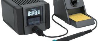
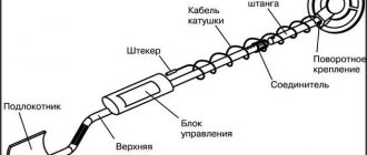
To perform various electrical work and assemble electronic circuits, a tool such as an electric soldering iron is often used. Its simplest type, which can be purchased at any hardware store, usually has a basic design.
It includes a heating element, a tip, a handle, usually wooden, and a power cable or cord. In some versions, the soldering iron can be equipped with several replaceable tips.
The power of such a soldering iron is fixed, most often 40 or 60 watts. But it is more convenient to use a tool with the ability to adjust power. Such models are also produced, although they are more expensive.
Why increase power?
To perform soldering work, tools with different parameters are required.
At the same time, it is impractical to have several soldering irons with different power and, accordingly, with different tip heating temperatures. When mounting components on a board, the tip temperature is required to be sufficient to warm the leads and melt the solder. Increased temperatures can lead to burning of individual elements, peeling of conductive paths from the board, and damage to wire insulation.
At the same time, using a soldering iron with lower power, and therefore with a lower heating temperature of the tip, allowing it to achieve a given value, forces you to increase the exposure time on the parts and solder.
As a result, prolonged heating causes components to fail, and the insulation may crack over time due to loss of mechanical properties.
Conclusion: when soldering, if heating of large areas and massive parts is required, it is necessary to increase not the temperature, but the power of the soldering iron, reducing to the possible minimum the time of contact of the tip with the leads of the part.
In this case, the solder must melt and provide reliable contact with the part, which in this mode will not be subject to overheating.
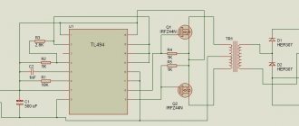
Schematic diagram of the power regulator.
I assembled this circuit so long ago that I don’t even remember when. It was published in the magazine “Radio” No. 2-3 for 1992 by I. Nechaev, and during the entire period of operation of the regulator there was not a single failure.
As you can see, the circuit is very simple, and consists of only two parts: a power circuit and a control circuit.
The power part includes thyristor VS1, from the anode of which an adjustable voltage is removed, through which the soldering iron is connected to a 220V network.
A control circuit assembled on transistors VT1 and VT2 controls the operation of the thyristor. It is powered through a parametric stabilizer formed by resistor R5 and zener diode VD1. Zener diode VD1 serves to stabilize and limit a possible increase in the voltage supplying the control circuit. Resistor R5 dampens excess voltage, and variable resistor R2 regulates the output voltage of the power regulator.
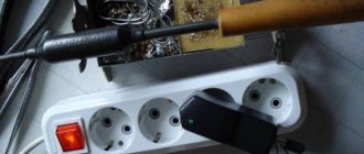
This is the small kit we will need to assemble a power regulator for a soldering iron.
Heating control
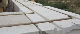
To heat a massive part to the required temperature, you need an equally massive soldering iron tip so that the heating rate is higher than the heat removal rate of the part.
A tool that can simultaneously cope with the tasks posed above is a fairly powerful soldering iron with temperature control.
That is, the maximum power of the soldering iron should be sufficient to heat large leads, and the temperature should be regulated within certain limits and selected in accordance with the operating conditions.
Then the massive tip will have greater thermal inertia and will heat the part to the required degree, without the risk of overheating.
There are several ways to adjust the temperature of the soldering iron:
- maximum-minimum heating (simple switch);
- dimmer adjustment;
- the use of control microcircuits in the handle of the device;
- external control unit;
- using a hair dryer.
Using an adjustable soldering iron, in addition to the advantages described above, you can significantly save on electricity consumption for large volumes of work performed, extend the life of the device due to less time operating at maximum power, and reduce the amount of harmful substances released during high-temperature soldering.
100 watt dimmer. Constructor.
- Price: $5.37 for 10 sets
- Go to the store
Hello. Overview of the electrical power control module with application examples. I bought this kit to change the power of a soldering iron. I used to make a similar device, but for a soldering iron that dimmer is too large, both in size and power, and it has to be placed in a separate box. And then I came across a subject that can be built into a network plug, not just any truth, but you can find it.
PCB size: 2*3.3cm Rated power: p=UI; 100W=220V*0.45A Model: 100W dimmer module; Rated power: 100 W;
Printed circuit board x1 pcs Potentiometer with switch WH149-500k x1 Potentiometer handle x1 Dinistor DB3 x1 Resistance 2 K, 0.25 W x1 Triac MAC97A6 x1 Capacitor 0.1 uF 630 V CBB x1
Board dimensions 30x20mm. The depth from the protruding contacts of the regulator to the thread is 17 mm. Mounting hole 9.2 mm. Thread diameter 6.8 mm.
I ordered a lot of ten sets. Each set is placed in a plastic bag.
Few details. Variable resistor with built-in switch.
The circuit diagram is like this, only the values are different.
The module can be soldered in a few minutes.
The wires are too thick and do not allow the variable to fully fit into place. Therefore, they should be soldered last, if they are needed, of course.
Now you need to pick up a fork. I haven’t found anything better than the Nokia charging case. The case is held together with screws, albeit with a tricky slot, but can be unscrewed with a regular flat-head screwdriver.
I take out the insides and make a hole in the lid.
That's it, the device is ready.
The regulator handle has the same texture and color as the body and does not create the impression of a foreign body.
All that remains is to connect the load - the soldering iron.
I puddle the spring contacts from charging with acid.
And I connect the soldering iron wire to the dimmer and contacts.
And I put all this inside the charging case. I did not secure the wire in the housing additionally; it fit quite tightly.
Now all that remains is to adjust the temperature. Although the soldering iron is 25 watts, it heats up to 350 degrees.
By rotating the regulator, I ensure that the tip is 270 C and move the regulator handle with the pointer to the screw to make it easier to navigate later. At this time, the soldering iron consumes 16.5 watts.
Video demonstrating power adjustment.
For the sake of experiment, I put the subject in the fan.
But here the speed adjustment can be done painlessly only within small limits. With a sufficient reduction in speed, the motor windings begin to hum, overheat, and sooner or later, rather sooner, with such operation the motor may burn out
Well, a universal regulator to which you can connect a soldering iron, a lamp and a fan. The case was taken from the power supply from the dekt phone. The power supply is the simplest - only a step-down transformer, the output is alternating current. So I took it apart without regret. The body was split into 2 parts along the seam by lightly tapping a knife with a hammer.
A pleasant surprise - the plug can be unscrewed, which makes the DIY process easier.
Of course, a little sawing is needed.
The necessary parts fit into the case quite compactly.
I connect the plug and socket with wires.
I place all this in the housing, where the dimmer is already installed. The wires in the photo are soldered incorrectly, due to carelessness. With this wiring, the current goes directly through the capacitor and the dimmer naturally does not work. And I thought - the marriage was over. I re-soldered the wires, as expected, to the contacts labeled “220V”.
Ready product.
I use the dimmer for its intended purpose - an incandescent lamp can be mentally dimmed.
During operation, I did not detect any excessive heating of the device, but I used the subject at a power lower than the rated one.
That's all. Thank you for your attention
Switches and Dimmers
The simplest temperature control is used in soldering irons with a switch that allows only two positions, and, accordingly, two temperature values.
At the minimum value, the soldering iron mounted on the stand simply maintains the tip in a heated state, and when you press a key or button, the tip heats up to the maximum temperature at which soldering is performed.
Obviously, of the advantages described above, such a soldering iron only has the ability to save energy. The main task of adjustment - the production of high-quality and safe installation of components - remains impossible.
The second type of adjustable soldering irons is dimmable. Their design involves inserting a dimmer into the break in the power cable - a device that limits the power consumption of the soldering iron.
In this case, it really becomes possible to adjust the temperature of the tip, but this is done due to a voltage drop in the dimmer.
Accordingly, there can be no talk of any cost-effectiveness of such a scheme. But the price of such devices is quite low and can play a decisive role in the choice.
Power regulator control circuit board.
If you do not have experience, then it is better to do the installation on thick cardboard. At the same time, you will understand how the elements are assembled into a circuit, and for such a circuit it is wasteful to spend textolite and ferric chloride. Moreover, almost all radio amateurs started with cardboard or plywood. I myself assembled my first transistor receiver on cardboard.
Everything is very simple here. You make holes in the cardboard and insert radio components into them. Bend the leads on the back of the cardboard and solder them together to assemble the circuit. Take a piece of cardboard to spare. Then cut off the excess.
This is the control circuit board I got.
PS I’ve forgotten how to assemble circuits on cardboard a little, it didn’t turn out very nice, but it’s better than hanging it.
Control units
The next type of soldering irons are more complex devices with a power supply, in which regulation occurs using a block of semiconductors and microcircuits. This unit is compact and can be located in the body of the soldering iron handle, which is very convenient.
The regulator may also be located on the handle. At a fairly modest price, this is a completely acceptable option that allows you to produce high-quality soldering.
Another type of adjustable soldering irons are tools with an external power supply. Thanks to the presence of these blocks, it is possible to operate the device on rectified direct current with stable voltage values.
Such a power supply also serves as a temperature stabilizer for the soldering iron, which will remain unchanged no matter how much the voltage in the network changes. Many radio components require this particular soldering mode.
The disadvantages of the models can be considered bulkiness and low mobility, but if you take into account that high-quality installation can only be done in an equipped workshop, and not “on the knee,” as is commonly said in such cases, then you can turn a blind eye to this.
The most precise adjustment and tuning can only be achieved using a soldering station, where a hair dryer is provided to assist a regular soldering iron, which is used to preheat the board or solder.
Construction and details.
The circuit uses two silicon transistors: KT315 and KT361. Since their cases are the same, they differ in the location of the letter marking. In the figure, these places are indicated by arrows.
For the KT315 transistor, the letter is always located in the upper left corner
case, and for KT361 the letter is always printed in
the middle of the case
. All other designations are: year of manufacture, month, batch.
The following figure shows a diode and a zener diode. Here you need to pay attention to the pinout of their conclusions. As a rule, the pinout is applied on the element body in the form of a strip, dot or several dots on the side of the designated pin
.
There are also diodes in which the diode symbol used on circuit diagrams is marked on the body. How exactly the designation is applied to the terminals means that this arrangement of the anode and cathode corresponds to reality.
For imported diodes and zener diodes, a strip is applied on the cathode output side, and for powerful ones, the pinout is applied in the form of a diode symbol.
For Soviet and Russian diodes, the pinout is slightly different from the imported one. Here we use a strip, dots, and the symbol of a diode. In addition, both the anode terminal and the cathode terminal are also designated. So, in any case, it is advisable to use a reference book or measuring device to more accurately determine the conclusions.
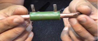
In the power regulator circuit, a thyristor is used as an adjustable element. The thyristor itself resembles a diode, only it has one more terminal - a control electrode.
In the closed state, the thyristor does not pass current, and if an unlocking voltage is applied to its control electrode, the thyristor will open and current will flow through the anode and cathode. The greater the unlocking voltage current, the greater the current the thyristor will pass through itself.
If problems arise with purchasing resistor R5, it can be made from two resistors connected in series. All other details are simple, so we won’t dwell on them.
As you may have guessed, we will take a surface-mounted socket as the body of the power regulator. When you buy, pay attention that the socket itself is made of plastic
, not ceramic.
This is necessary so that if suddenly the thyristor does not fit into the housing, then you can always cut off an extra piece from the plastic.
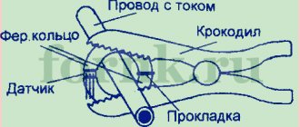
We will assemble the regulator from two parts. It is better to assemble the low-voltage part on foil fiberglass, thick cardboard or any other dielectric material - it will be neater. But we will make the high-voltage part by hanging installation, as shown in the figure below.
Here the holes are indicated by black dots, and all connections between points and parts are paths
, shown with blue lines. The control circuit board and the power section are connected to each other by three red conductors.