An oscilloscope is a measuring device that shows the change in signal amplitude taking into account a time graph. Such equipment is used in home and professional laboratories. Using this converter, electrical circuits are configured, faults are found and eliminated in computers, televisions, amplifiers, and power supplies.
Modern oscilloscope
General definitions
A cathode ray oscilloscope, or oscilloscope, displays a graph of signal amplitude versus time on its screen. Despite its complex appearance, working with the device does not cause significant difficulties, just like with a strain gauge. Numerous controls help you adjust the image scale at a user-friendly level.
Oscillogram
This test cycle of the operation of internal combustion engine injectors is used to repair electronic components and adjust the ignition angle. The figure clearly demonstrates what an oscilloscope is needed for. Using a conventional multimeter it is impossible to obtain a similar result in order to objectively evaluate the shape of a complex signal.
The purpose of an oscilloscope is easy to determine from the list of typical tasks:
- measurement of time, amplitude and frequency characteristics;
- study of phase shifts in different sections of circuits;
- identification of distortions in the shape, constant and variable components of the signal.
Classification
Capacitor energy
Based on the type of circuitry (electronic components) used, a distinction is made between digital and analog measuring instruments. Simple models show only a dynamic picture. Modern ones are equipped with a memory function to provide better conditions for studying complex processes. Some electronic oscilloscopes are capable of displaying up to 14 or more signals simultaneously. To study optical signals, manufacturers produce stroboscopic high-speed modifications.
Special mention should be made of specialized set-top boxes that connect via a standard port or communication card to a laptop (desktop computer). Such combined equipment can be reconfigured using specialized software.
The vst plugin provides convenient processing of wave processes in the audio range
Device
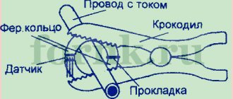
Current transformer - operating principle, purpose and device
What an oscilloscope is can be found out using a typical design example:
- a vacuum tube (CRT) is coated on the inside with a phosphor that glows when hit by electron beams;
- the horizontal scanning unit generates sawtooth signals along with pulses to “quench” the beam when returning to its original position;
- the amplifier increases the amplitude of the input signal to the required sensitivity level of the CRT;
- To synchronize the scan, an internal clock generator or an external source is used.
Oscilloscope device
Screen
The picture above shows a block diagram of an oscilloscope with a cathode ray tube. Modern models often use displays created using liquid crystal technology. They are more economical and reliable, and weigh less. The coordinate grid is applied to a transparent overlay or generated using software.
A modern screen allows you to make an oscilloscope smaller; this picture demonstrates what it is in practice.
Signal inputs
Multibeam oscilloscopes retain the basic principle of operation, but the signals are supplied to separate channels. Each path has its own amplifier. The adjustment equalizes the amplitudes for convenient comparison of several indicators.
For your information. If there is too much DC component, the beam is deflected off the screen. To return it to the working area, switch to the “closed” input mode with an isolation capacitor.
Sweep control
The following types of sweep are used in oscillography:
- “Automatic” - pulses are generated according to a given mode without additional intervention from the user.
- Standby – used at low signal levels (absence). It is triggered at a certain edge (fall) level. In some cases, external control is used.
- One-time – forcibly activated. It is used to study single signals (sequences of several pulses).
Synchronization of the sweep with the signal under study
To ensure that the “picture” remains motionless, the trajectory of the beam across the screen must be coordinated with the process of signal transmission. The problem is solved by triggering a sweep at a zero or other level at the input. The limitation is the frequency perception threshold of the human eye. From 18-22 Hz and above flicker is not noticeable.
For your information. Lack of synchronization appears as a moving image. By manual adjustment, triggering on the front (fall) is set, and the optimal level for stabilization is selected.
Description of the block diagram and blocks of the electronic oscilloscope
An electronic oscilloscope is designed for visual observation, measurement and recording of electrical signals presented in the form of voltage.
A simplified block diagram of the oscilloscope is shown in Fig. 5.1.
An electronic oscilloscope (EO) consists of a cathode ray tube (CRT), a scan generator (SU) with a synchronization circuit (CS), amplifiers for vertical (VV) and horizontal (UG) deviations, and a power supply unit (PSU).
The main measuring unit of the EO is a CRT, which converts the value of the voltage under study into the movement of the electron beam. Modern oscilloscopes use hot cathode CRTs with electrostatic focusing and control. A CRT is a flask in which a vacuum is created. Inside the flask are located:
- filament (H), designed to heat the oxide cathode (K) in the shape of a cylinder and emitting a flow of electrons;
-modulator (control electrode M) in the form of a cylinder with a hole in the end part. The modulator has a negative potential relative to the cathode (–10–60 V). Changing the modulator potential using potentiometer R1 “Brightness” provides a change in the electron density in the beam and thereby allows you to adjust the brightness of the image;
-the first A1 and second A2 anodes. The first anode, called the focusing anode, is a hollow cylinder with diaphragms and has a positive potential relative to the cathode (+300 +1000V). By changing the potential of the first anode using the R2 “Focus” potentiometer, the beam is focused. With good focusing, the beam diameter reaches 0.2–0.3 mm. The second anode A2, called accelerating, has an even higher positive potential relative to the cathode (+800 +5000V) and is designed to accelerate electrons in order to increase image brightness.
A group of electrodes, including a cathode K with a filament H, a modulator M and anodes A1 and A2, forms a so-called “electron gun” designed to produce a narrow beam of electrons - an electron beam.
The inside of a CRT screen is coated with phosphor, a substance that can glow when bombarded with electrons. Electrons, bombarding the screen, knock out secondary electrons from it, which flow onto the side walls of the CRT, coated with a special graphite compound (aquodag), which is a good conductor. Akvodag is connected to the second anode, due to which the current circuit through the tube is closed. The electron beam current is typically hundreds of microamperes.
The CRT deflection system consists of two pairs of plates Y and X located in mutually perpendicular planes. Each pair of plates forms a capacitor. An electron beam, passing between the plates and entering the electrostatic field of the capacitor, is bent, and after leaving the field of the deflecting plates, the electrons
inertias fly in a straight line (Fig. 5.2).
In addition to the CRT, the following main parts can be distinguished in the EO block diagram (Fig. 5.1):
1) vertical deflection channel (Y channel, including a voltage divider (DV) designed to attenuate large voltage signals (units to tens of volts) and a UV amplifier to amplify weak signals (tens to hundreds of millivolts). The signal amplification in the Y channel is adjusted in steps with using special switches on the front panel of the EO. Fixed values of the scale my along the Y axis, called the deflection coefficient, can be set in a wide range. For many EOs my=10mV/cm 20V/cm;
2) horizontal deflection channel (channel X), including a GR scan generator with a CS synchronization circuit and a CG amplifier. The need to introduce HF and UG amplifiers is explained by the low sensitivity of the CRT. Basic requirements for modern EO amplifiers:
— high gain (Ku = 30 30000) and its constancy over a wide frequency band (from 0 to 100 MHz and above);
— linear relationship between output and input voltage;
— high input resistance and low input capacitance so that connecting the EO to the circuit under study does not change its operating mode. For most EOs Rin = 1 MOhm, In = 30 pF.
Channel X of the EO can operate in two main modes – scanning and amplification of the signal applied to “Input X”. The channel operating mode is selected using switch SA1: position 1 corresponds to sweep mode, position 2 to signal amplification. In the scanning mode, the voltage of the sawtooth GR generator is supplied through the UG amplifier to the horizontal deflecting plates X. The linearly increasing voltage of the GR ensures horizontal movement of the beam at a constant speed and allows one to observe the curve of the change in the test voltage over time. The principle of operation of the GR follows from Fig. 5.3.
The GR generator includes a source of constant current I with a high internal resistance, a capacitor C and an electronic switch with a switch K that shunts the capacitor. When the electronic switch K is opened, capacitor C begins to charge from the current source I, while the voltage on the capacitor increases according to a linear law (section ab)
.
At the moment when the voltage UС reaches a certain value UСm, the electronic switch closes and the rapid discharge of the capacitor begins (section bv). In the self-oscillating mode of operation of the GR, after the capacitor is discharged, switch K opens again, regardless of the presence or absence of a signal at input Y, and then the process is repeated. In standby mode, after switch K is closed and the capacitor is discharged, this state of the GR is maintained until the trigger signal arrives. The transition from self-oscillating to standby mode is carried out using the adjustment displayed on the front panel of the EO. The sweep frequency can be adjusted by changing I and C. The selection of the required scale mx, called the sweep factor, is carried out using a special switch on the front panel of the EO. Modern universal oscilloscopes have a number of fixed scale values along the X axis (mx = 0.02 μs/cm 100 ms/cm).
The DS synchronization circuit is designed to provide a stationary, stable image on the oscilloscope screen. The image will be motionless if the scanning period Tr is a multiple of the period of the process under study T. A constant frequency multiplicity is ensured by automatic synchronization, while the synchronization circuit controls the operation of the scanning generator. Depending on the source of the synchronizing voltage, internal, external synchronization and synchronization from the network are distinguished. With internal synchronization, the operation of the scan generator is controlled by a pre-amplified voltage under test (Fig. 5.1). With external synchronization, the voltage is taken from some external source. When synchronizing from the network, the synchronizing voltage is taken from a special winding of the power transformer of the power supply.
The power supply unit is designed to generate constant voltage to power the electrodes of the CRT and all other components. The CRT electrodes are powered using a voltage divider R1–R2–R3 (Fig. 5.1), from which a potential negative relative to the cathode is supplied to the modulator and positive voltages to both anodes.
Oscilloscopes are also equipped with calibrators - special devices that allow you to accurately set the sensitivity vertically (volts/division) and horizontally (seconds/division), i.e. use an oscilloscope for measurements.
Main settings
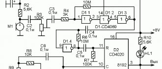
Programmable thermostat W1209
To select an oscilloscope, it is recommended to correctly evaluate the following characteristics:
- to eliminate distortion when working with several high-frequency signals, you should purchase a two- or multi-beam device;
- in different models the error is 5-15%, so limited measurement accuracy should be taken into account;
- digital devices are equipped with color screens, various synchronization devices, and additional service modes;
- The functionality of analog devices is more modest, but they are cheaper;
- the limited capabilities of amplitude-frequency converters make it difficult for high-quality digital electronics to process high-frequency signals;
- Freeze mode with zoom function will help you study the smallest details of complex images.
Before a detailed analysis, you need to clarify what exactly the device is intended for. Next, compliance is assessed according to the following parameters:
- bandwidth;
- frequency range;
- input impedance;
- permissible amplitude values (variable and constant components);
- measurement error;
- isolation between channels;
- internal memory capacity (digital technology).
Areas of use
The oscilloscope is designed to study dynamic processes. To use the device correctly, you should not exceed its design capabilities. Below are examples of solving practical problems.
Observing Lissajous figures
When signals with approximately equal frequencies are simultaneously applied to the oscilloscope inputs, characteristic images will be visible on the screen. This method is used to tune the generator according to the reference sample.
Lissajous figure on a CRT analog device
Cursor measurements
To increase the accuracy of measurements, auxiliary coordinate bars (cursors) are displayed on the screen. If well equipped, the oscilloscope displays individual indicators in digital form.
Mathematical functions
Some models of modern oscilloscopes (units for connecting to a computer) are capable of processing signals using a complex algorithm. The required option is described by the corresponding mathematical function: addition, subtraction, etc.
Capture a TV signal line
In accordance with the name, this mode is intended for studying a television signal. The main feature is special synchronization, which allows you to display the required number of lines on the screen.
Specifics of product selection
When purchasing such highly specialized equipment, a number of important parameters should be taken into account. First of all, you should pay attention to the following:
- Bandwidth. On average, the band should be 5 points higher than the frequency value of the signal being studied. To use a simple audio amplifier and digital circuit, 25 MHz will be sufficient. Scientific research and professional research will require the use of a device with a minimum bandwidth of about 150 MHz.
- Type of food. In case of carrying out work away from the network or on the road, it is recommended to purchase a model with a battery. In any other situation, it is advisable to use network-powered equipment.
- Sampling frequency. This item affects the quality of image resolution on screens and the number of signal samples per second. For a more accurate image, an increase in the number of signal points will be required. Frequency is also important for measuring single-shot and transient events.
- Number of channels. Channels affect the number of independent signals shown on the display. Provide the ability to analyze and compare several graphs simultaneously. Working with simple technical devices does not require more than 3 channels. More advanced equipment should be equipped with a logic analyzer and 16 channels.
You might be interested in: Design, principle of operation and application of an ionistor
Additional features
In modern electronics, it is often necessary to test analog and digital signals simultaneously. To work with such tasks, an oscilloscope with a built-in logic analyzer is useful.
Some modern devices are equipped with a memory block segmentation mode. This is useful for long-term signal monitoring with automatic comparison using a standard form. Only deviations (noise, distortion) will be registered and recorded.
Specialized oscilloscopes (scanners) are produced for automobile service stations. In addition to special adapters, such devices are supplemented with software. This equipment is used to monitor the functional state of sensors and other electronic components through an on-board computer.
Detailed classification of the device
Modern oscilloscopes have a powerful set of measurement applications, deep memory, a touch capacitive display, and the ability to quickly update signals on the display. Familiarization with the classification is an integral step in working with equipment. The equipment is subject to internal division according to purpose and operating logic:
- Strobe.
- Real time or analog.
- Storage: CRT-like analog and digital.
Devices with continuous scanning are included in a separate group. They allow you to record the curve on a special photographic tape. Depending on the number of rays, there are two-beam, single-beam, three-beam and so on. The pinnacle of automation is considered to be 16 beams or more. The parameter affects data synchronization.
Periodic scanning technology is characterized by the following division: stroboscopic, high-speed, conventional and universal, special storage. Digital models are characterized by a combination of several parameters. Less common are oscilloscopes whose purpose is combined with another measuring instrument. Their official name is scopmeters.
You may be interested in this Definition and application of hand and gimlet rules