The operation of industrial installations and electrical networks is impossible without a properly designed and equipped system in compliance with the requirements of the current PUE (see paragraph 1.7). With its help, it is possible to organize reliable protection of working personnel and ordinary consumers from damage by dangerous voltages and electric shock. Depending on the means by which it is provided and according to what schemes it is organized, a distinction is made between artificial and natural grounding. The second type of grounding systems includes sections and elements of building metal structures and pipelines located in the ground, consisting of sections of pipes, fittings and other elements. Artificial varieties of these structures include specially man-made grounding devices (GD), otherwise called protective ground loops.
In view of the unreliability of natural structures, which do not guarantee reliable flow of emergency current into the ground, according to the rules of the Electrical Installation Code for existing electrical installations, it is necessary to install special chargers. Only in this way will technical personnel be able to control the resistance value of current spreading into the ground, which is the main indicator of the effectiveness of ground electrodes.
Its exact value is usually determined by the current state of the soil, as well as the technical parameters of the structure and the properties of the materials used in its manufacture. The determining factor in calculating this value is the area of direct contact with the ground of the pins, plates included in the structure, as well as sections of pipes and similar elements.
What are PE and PEN conductors
According to GOST R50571.2-94, the classic grounding scheme contains the following types of buses, differing in functionality:
- Phase conductors.
- Bus N, which is the so-called “working zero”, serves to create a load current circuit (its other name is the neutral of a 3-phase network).
- PE is a specially equipped protective neutral conductor used to organize re-grounding and grounding at the receiving (consumer) end.
- PEN is a combined conductor that performs the functions of both buses discussed above.
Color marking of wires in the diagram: F1-red, F2-yellow and F3-green, N - blue, PE - yellow-green, and PEN - a combination of two colors.
Three-color markings are traditionally used for phase wires: F1-red, F2-yellow and F3-green. Neutral conductors in working circuits are also distinguished by a special color (N - blue, PE - yellow-green, and PEN - a combination of two colors).
Additional information: Each of these conductors is selected according to the cross-section of the bus, which should not be less than half of the same indicator for any phase conductor.
The ability to distinguish between types of neutral wires will allow the user to understand the following important issues:
- How are protective PE, N working and combined PEN conductors organized?
- For what purpose is each of them needed?
- How is the ground loop made on the consumer side?
Answers to these questions will bring the interested user closer to understanding the operating principle of grounding and grounding circuits. For those who have not dealt with this topic for a long time, let us remind you that grounding of electrical networks and equipment means the connection of conductive parts open to accidental contact with the ground.
What is neutral
To understand how different grounding methods differ from one another, it is important to understand what constitutes a neutral provided in any electrical network.
Zero point of three-phase electrical networks: a) tightly grounded, b) grounded through high-resistance resistance, c) isolated from ground
Its presence as part of a set of wires that ensures the transmission of electricity from the substation to the consumer is explained by the following circumstances:
- when organizing a three-phase power supply, the current components in each phase should theoretically be equal in magnitude;
- when flowing along the reverse branch, called neutral, due to vector addition (three phases shifted relative to each other by 120 degrees), they, in fact, must cancel each other out;
- in reality, due to phase imbalance caused by uneven load distribution, the reverse component of the current through this wire is constantly not equal to zero.
Important! Moreover, the amount of misalignment can reach significant values, which leads to the need to pay special attention to the neutral conductor.
Its total thickness, in particular, according to the PUE, should not be less than half the cross-section of the phase busbars. Otherwise, due to significant current loads, such an unpleasant phenomenon as “zero burnout” often appears. That is why it is not allowed to install protective devices in the neutral conductor that lead to its breakage when triggered in the event of overload.
Grounding design
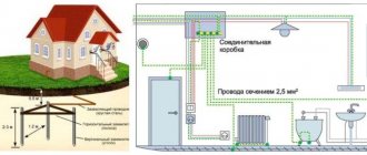
Working grounding consists of iron pins driven into the ground, acting as conductors, to a depth of about 2-3 meters.
Such metal rods connect the grounding terminals of electrical equipment to the grounding bus, thereby forming a metal connection.
There is a metal connection in every residential building. This is a welded iron structure that connects the upper ends of the ground electrodes to each other. She is taken to the entrance panel of the house for further distribution to apartments.
A bus or wire with a cross-section of at least 4 square meters is used as a grounding conductor. mm, painted in yellow and green stripes. The cable is primarily used to transfer functional ground from busbar to busbar.
For safety reasons, the electronic resistance of the metallic ground connection is periodically checked. It is measured from the ground terminal of the electrical installation to the ground ground loop farthest from it. The resistance value in any part of the working ground should not exceed 0.1 Ohm.
TN and its varieties
Existing grounding systems for existing electrical installations are classified according to the following main characteristics:
- Operating state of the neutral (solidly grounded or completely insulated).
- The order of its wiring throughout the entire section of the route from the substation with a step-down transformer to the consumer's electrical installation.
- Features of connecting the grounded load to the neutral.
The main working document defining the division into types of grounding on the territory of Russia is the PUE (in particular, clause 1.7). It provides a description of the characteristic features by which it is customary to differentiate existing storage systems. Their abbreviated designation is based on a combination of the first letters of the words “Terre”, “Neuter”, “Isole”, which is translated from French as “earth”, “neutral” and “isolated”.
TN grounding schemes in 3 different designs, designated as TN-C, TN-S, TN-CS
The meaning of each symbol used in their designation is deciphered as follows:
- T – means grounding in general.
- N means it is connected to the neutral.
- I – isolated state of the bus.
- C (from the initial letter of the word “common” or common core) - informs about the joint installation or combination of the functions of the working and protective conductors.
- S (from the initial English icon “select”) - means separate use of the same wires.
In the above marking methods, by the sequence and type of letters, one can judge the method of protecting the current source and the features of the protective grounding circuits installed on the consumer side. When organizing industrial electrical networks, TN, TT and IT grounding schemes are distinguished. The very first of them, which is among the most common, is found in 3 different designs, designated as TN-C, TN-S, TN-CS. To clearly understand the main differences between these methods of arranging protection, you will need to consider each of the proposed options in more detail.
Important! From the fragment of the designation “N” it follows that to connect the neutral conductors (regardless of their direct purpose), a solidly grounded neutral of the supply windings of the step-down transformer is used.
It is also important to remember that all conductive housings and screens on the consumer side are connected to the neutral conductor connected to the same neutral (in other words, they are reliably grounded).
The circuit arranged in this way has the following characteristic feature: its “zero” or bus N is connected to its own ground loop available at the transformer station. Such a neutral is called solidly grounded because neither an arc suppression reactor nor other types of protective equipment are installed between it and the ground loop. Below is a description of the various modifications of TN.
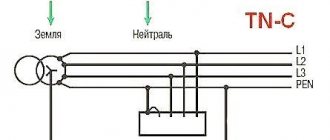
TN-C
According to the letter designation used in the name, it is characterized by the combination of two current-carrying busbars (remember that “C” is common in English or a common wire). The classic TN-C grounding scheme is a traditional four-wire power supply line with three phase and one neutral conductor (see photo below).
Traditional four-wire power supply line with three phase and one neutral conductor
The last of the designated types of buses is represented in this case by a combined electrical conductor, tightly grounded to its own circuit on the substation side. At the receiving end, all open conductive elements of the housings and metal parts of the devices are connected to it via copper bars (in addition, the working zero is connected here). This system has a number of disadvantages, the main ones are listed below:
- the possibility of loss of protective functions in the event of an accidental break or burnout of the neutral (zero conductor), leading to the threat of high voltage damage;
- the absence of a separate conductor in electrical outlets that provides full grounding (the so-called “splitting” on the panel by specialists, as a rule, is not taken into account);
- impossibility of organizing re-grounding due to the combination of protective and operational functions;
- as a necessary measure - the need to use a protective grounding circuit, that is, connect the equipment housing to the neutral wire.
Additional information: In the latter case, the main protection device is a threshold element (automatic) installed on the consumer side and instantly disconnects the power circuit when a phase contacts the housing.
The high speed of operation of the circuit breaker does not allow dangerous currents to reach values that threaten the life of a person who touches the equipment body. The most important limitation when it comes to organizing forced protection of household appliances is the prohibition on combining grounding and potential equalization in apartment bathrooms. Today this scheme is used extremely rarely in practice; it is still preserved only in buildings belonging to the category of old housing. In addition, it is sometimes used in electrical networks intended exclusively for street lighting, in which the likelihood of exposure to dangerous potentials is very small.
Grounding systems TN-S
The TN-S protective circuit, which is more universal and safer in terms of operation, is distinguished by separate laying of the working and protective zero busbars (see photo below).
More versatile and safer in terms of operation, the TN-S protective circuit
It was developed and then implemented into the network structures of existing electrical substations back in the 30s of the last century. Along with the high level of security provided by this system, this approach to arranging protective circuits has one, but very important, drawback. It concerns the economic side of laying routes and is associated with a significant consumption of cable material (the total length of the wires in this case doubles).
Accordingly, the costs of organizing the installation of such a system increase noticeably. Another characteristic feature of this method of protection against electric shock is an increase in the number of conductors entering the input switchgear to the consumer.
Please note: In this case, the supply of 3-phase voltage is carried out through five wires, and with single-phase power supply - through three (instead of 2 in the TN-C system).
For grounding carried out using the “tight” method on the side of the source of supplied energy, a combined zero bus is used. The provisions of GOST R50571 and the latest (updated) version of the PUE contain recommendations for installing a TN-S system at newly commissioned facilities, which allows ensuring the required level of safety. On the other hand, its widespread implementation in all operating and starting-up energy complexes is hampered by the high costs of laying cable products along two parallel lines. In addition, this is hampered by the tradition that has developed over many years and the attachment of our country’s energy sector to four-wire, three-phase power supply circuits (two wires at the entrance to the apartment).
TN-CS
As an intermediate option, which absorbed the positive aspects of both systems considered, another scheme was developed, characterized by the following features:
- to optimize the funds spent on its arrangement, the initial section of the route is laid in the form of a combined conductor, and the remaining part is manufactured in a completely separate form (like TN-S);
- such a division makes it possible to obtain a completely usable system that does not require significant costs and is not inferior in safety to the second (separate) option;
- splitting into two conductors (protective and zero bus) at the input to the consumer allows you to isolate them functionally in this not very long section;
- thanks to this technique, it is possible to combine the possibility of obtaining full vertical grounding and save on laid wires;
- vertical grounding is metal pins driven into the ground, connected by welding with steel jumpers (the latter are conventionally classified as horizontal elements of the circuit).
Please note: In this case, three wires are supplied to the entrance to the apartment and to the sockets in the residential premises instead of the two used in the TN-C system.
Their presence allows you to organize complete and reliable re-grounding in a private house.
An intermediate option that incorporates the positive aspects of the considered TN-C and TN-S systems
When comparing TN-CS and TN-S grounding systems, it is necessary to note the following differences:
- the first of them has significant disadvantages, similar to the same disadvantages as the completely combined scheme for laying neutral conductors;
- they are that in the event of accidental damage or burnout of the PEN wire in the area from the transformer substation to the splitting point, all serviced equipment will be left without protection and zero;
- secondly, in this case, by analogy with the first option, it is impossible to use the grounding of the circuit, which is often used to protect people and electrical installations;
- in the TN-S system, for obvious reasons, this cannot happen, since the entire operating current load falls on the corresponding wire N, laid separately from the protective bus PE.
For this reason, when developing and implementing the TN-CS system, current regulations require special measures to protect the combined PEN wire from unintentional damage.
Purpose of protective grounding
Already from the name itself it is clear that the purpose of grounding is to protect a person from electric shock. Where can it (current) appear? On all metal parts and housings of various electrical appliances that operate on electricity. But, you say, now there are such good insulating materials, high technologies, etc. And you will be right. But we shouldn’t forget the accidents that happen quite often in our lives.
A simple example from our everyday life. Imagine an ordinary small oven for cooking chicken, cakes, and pastries. It has, like many household appliances (refrigerator, bowler, microwave, pump, etc.) a metal body. Over time, the insulation on the wires may collapse, melt, or simply burn off a wire. There are many reasons: long operating time, high temperature, vibration, manufacturing defects, violation of the operating rules of the device and much more.
This “bare wire”, which is energized, may accidentally end up on a metal casing, which means that it will all be energized (casing). What can happen in this case? There may be a short circuit, and then the automation will simply turn off the electricity. Or maybe nothing will happen, everything will work until a person touches the oven body.
When touching a metal part (conductive), a person will receive an electric shock. No one knows how strong he will be. Everything here is individual and depends on hundreds of factors. We will not consider them (factors), but any electric shock is a strong stress for the body, especially for the heart. It’s good if everything ends well, but there are deaths. I don’t want to scare anyone and give up electrical engineering, but the statistics are not forgiving and show specific facts.
Protective grounding
So, I think it’s clear why they do grounding. It is no coincidence that in any household appliance the power wires are made of a three-core wire and the plug has a grounding terminal. By the way, the requirements for electrical wiring have now changed significantly, and only a three-core wire is used to power any devices. In a word, the presence of protective grounding is mandatory. If previously two strands of wires (phase and neutral) were enough in the electrical wiring of a house or apartment, now it is no longer possible to install “such a disgrace.” The presence of “land” is a mandatory and necessary requirement. Even bathhouse lamps have a grounding wire on the terminal block connected to the housing.
TT and IT grounding systems
Schemes of grounding systems TT and IT
TT circuit
TT grounding is used in those exceptional cases when it is not possible to provide reliable protection using the TN-CS system or is associated with significant difficulties. This mainly concerns areas remote from urban centers, usually referred to as remote rural areas and regions. In these conditions, TT grounding systems are increasingly being used, which provide for a “dead” connection of the transformer neutral to the ground with subsequent transmission of 3-phase voltage using a four-wire line.
Additional information: The fourth bus in this case is the so-called “functional” or working zero N (also known as the neutral wire).
On the side where the loads are located, as a rule, not repeated, but local grounding of a vertical pin type is installed. All copper PE busbars are connected to it, which are connected on the other side to the electrical equipment housing.
Four-wire TT grounding system
This system was officially approved for use in Russia not so long ago. Despite this, it quickly “took root” in various operating conditions of power systems and is widely used in rural areas located considerable distances from urban centers. Within city limits, the TT type grounding scheme is often used to provide electricity to various retail outlets and small temporary buildings associated with the provision of household services.
Additional information: In addition, these systems are often used to supply power to cabins and construction trailers temporarily installed within the boundaries of construction sites.
With this approach to organizing protective grounding systems, special requirements must be met. They concern the issue of installing devices and residual current devices (RCDs) in the serviced circuits, as well as special lightning rods with a lightning protection function.
Interference and proper grounding
I would like to draw your attention to another reason for interference in a PC. These are the so-called “ground loops”, which arise when the circuit is grounded at several points with different potentials, leading to the appearance of differential currents in the ground circuit, causing interference. Alexey Prokopyev wrote to me.He continued.
This is what I mean: now many cases have analog audio connectors on the front panel. The front output of the sound card is connected to these connectors using a shielded wire. At first glance, everything is great. But some case manufacturers additionally connect the screen of this wire to ground, for example, USB connectors, also located on the front panel, and (or) connect all this to the chassis. Naturally, the ground potential at the output of the sound card and at the digital connectors cannot be the same (at least in my case, the amplitude of the difference in alternating current is about 200 mV - I looked at it with an oscilloscope). This interference causes a corresponding current in the shield of the audio cable, disrupting the normal operation of the circuit and leading in many cases to very unpleasant acoustic noise at the front audio connectors. There is only one way out - disconnect the second grounding point of the front audio cable shield, and leave it grounded only on the sound card. (emphasis added)
Grounding
The problem of interference does not end with those that I talked about in the articles “Computer as a source of interference” and “Types of interference in information transmission lines and ways to deal with them.”
I came across them when I was working on high-frequency (frequencies 30-100 MHz) wideband amplifiers. There, an incorrectly selected grounding point turned the amplifier into a generator.
This is interference, the so-called “Ground loops”.
When considering grounding methods, keep in mind:
- any conductor has an impedance consisting of an active and inductive component,
- grounding points separated in space have different potentials,
- A power ground is never suitable for use as a signal ground.
In power circuits with high currents, in systems where they work with extremely small signals or devices operating at frequencies exceeding 30-100 MHz, the value of the conductor impedance begins to significantly affect the level of interference in the system.
In the case of a haphazard arrangement of grounding points in the listed devices, the difference in their potentials leads to the appearance of flow currents. These currents flow along the path of least resistance. As a rule, these are copper braided screens. The current flowing through them interferes with the signal circuits and is radiated into space.
This is especially important in modern computers, where the clock speeds of processors, chipsets, video processors, and memory have already exceeded 1 GHz, and other “slow” devices have about hundreds of megahertz.
Modern electronic devices and PCs use several types of grounding connections.
Grounding at one point
| Fig.1. Serial ground connection. At point A, the potential is equal to UA=(I1+I2+I3)R1, which differs from the potential of points B and C. This potential UA is interference for nodes 1,2,3, propagating along the grounding circuit and being re-radiated. Not only does noise propagate through this circuit, but also positive or negative feedback occurs (in amplifying devices). | Fig.2. Parallel ground connection. The potential at points A, B, C is determined only by the currents of nodes 1,2,3 flowing through their ground circuit resistances. UA=I1*R1: UB=I2*R2; UC=I3*R3 In this case, feedback does not occur and interference from node 1 can reach other nodes only through radiation. |
Grounding diagram Fig. 1. should not be used in systems with a large spread of power consumption and in high-speed pulse circuits. The most critical nodes of the circuit should have the shortest connection to ground.
At first glance, it may seem that you connected the ground as shown in Fig. 1a and 2a and everything is fine.
But this is only at first glance.
Real conductors have their own resistance and inductance. Despite the smallness of these values, the impedance of the grounding conductor begins to affect itself at currents exceeding 1-10 A or at a frequency of flowing currents greater than 100 KHz. Therefore, the diagrams in Fig. 1b and Fig. 2b appear, where R represents this resistance. And immediately the problem of noise appears.
Of the grounding connection diagrams shown in Fig. 1 and 2, the diagram in Fig. has the lowest level of interference. 2. But it requires the largest number of wires.
Using the circuit in Fig. 2, when pulsed high-frequency currents flow (this is typical for PCs), the ground impedance increases due to the inductive component. This also helps to increase the inductive coupling between the grounding buses.
In order for the grounding wires not to emit radiation, their length should be minimal (no more than 0.05λ). In the case of pulsed currents, it is difficult to determine fmax and, accordingly, λ without experience, therefore the length of the grounding conductors should be minimal.
Let's consider another option for connecting the ground.
Spaced Lands
To minimize the influence of ground impedance on high-frequency and pulse currents, a multi-point grounding system is used.
Figure 3. Grounding at multiple points.
Despite the finite impedance of the grounding conductors, this scheme makes it possible to reduce their value due to short conductors. But such a scheme places increased demands on grounding surfaces. Because the ground surface itself may have high impedance.
The grounding surface must have:
- high electrical conductivity,
- low inductance (width / length ratio no more than 10),
- high current penetration depth (it is not allowed to use materials μ of which μ>1),
In HF and pulse current circuits, it is advisable to plate the grounding surface with silver and place it on insulating supports. The grounding surface itself must be grounded at one point to a special instrument (measuring) ground.
Such a grounding surface will be close to ideal.
They are used in instrument racks operating in high-noise environments.
Figure 4.
Figure 4 shows an approximate organization of grounding in such a rack.
Corpus lands
Electronic devices in any complex system are mounted in racks and cabinets. Safety precautions require grounding of such racks (cabinets). The ground of such systems is always very noisy and has a spreading resistance value determined by safety requirements. And this, if my memory serves me right, is something like 0.5 ohm.
G. Ott recommends using what is shown in Fig. 5 for rack 1 (rack 2 is an example of incorrect connection) grounding connection diagram.
Figure 5.
My experience shows that if there are a large number of noisy racks in one room, it is necessary to use separate grounding to ground them. Such systems should have separate power and instrument grounds and look like this:
Figure 6.
Conclusion
I tried to talk about the methods of combating interference outlined in the book - G. Ott, “Methods for suppressing noise and interference in electronic systems” by optimizing the grounding of nodes. These are solutions proven by my practice that I can recommend for use. But here some typos have been corrected and some additions have been made.
A. Sorokin. year 2009.
<<back>> <<to the beginning>> <<to the main>>