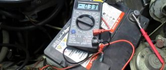
Basic moments
A multimeter is used as a thermometer if it is necessary to measure temperature in difficult conditions - an open flame, toxic substances, difficult access to an object, an object that is too hot.
Many multimeters have a built-in temperature measurement function. In this case, using the device is not difficult, since you do not have to make any changes to its design, you just need to figure out which mode to choose.
Usually this mode is marked with the letters “temp”, and the multimeter comes with a thermocouple, which is a wire with a sensor. There are two sockets on the housing to connect a thermocouple.
Most testers are capable of working with temperatures ranging from -40 to 1000 degrees Celsius. If you have purchased an inexpensive multimeter, you should pay attention to which thermocouple is included.
The fact is that most multimeters have fairly thin wires that can melt when exposed to temperatures above 250 °C. It is also necessary to pay attention to whether it is possible to measure the temperature of liquids or only gases.
If you are going to work with high temperatures, then it is better to replace the standard thermocouple with a special one, the design of which is designed for measurements in more difficult conditions.
For some devices, you will need to use a special adapter, since multimeters have single inputs, and a professional thermocouple has a miniature plug. After connecting the thermocouple, you must select the temperature measurement mode: it can be in degrees Celsius or Fahrenheit.
In order to find out what the temperature is, you need to touch the tip of the thermocouple to the object of interest. The data will immediately appear on the electronic display.
The duration of contact with the object is only 2-3 seconds; for accurate measurements, the contact must be tight. You can check if your multimeter is working correctly by comparing its readings with those of a thermometer. It is also important to monitor the polarity of the thermocouple connection.
No special mode
Is it possible to measure temperature with a multimeter that does not have a special mode for this? It turns out that this can really be done, but the device will need to be slightly upgraded.
You need to purchase an LM-35 microcircuit, with its help the temperature readings will be converted into voltage, and the device will be able to recognize the data, but will indicate them in Volts. For example, 0.30 Volts will need to be understood as 30 degrees Celsius.
The use of a microcircuit does not require complex intervention in the design of the device and allows you to use any multimeter to measure temperature.
In order for the chip to work, you will need:
- three wires that can be connected to the 10-ohm output of the device;
- a separate power source of at least 4 Volts, that is, 2 flat batteries.
If you need to measure not only positive, but also negative temperatures, you will also need to connect a reference voltage source.
The microcircuit itself is easy to connect. It has three connectors for positive and negative wires and an output sensor. This approach will allow you to transform any multimeter, making it more functional, while the design will be inexpensive.
Checking the temperature sensor with a tester
The question of how to check a temperature sensor with a tester is quite relevant for motorists. In order to carry out the necessary measurements, you can use any multimeter; in addition, you will need to remove the sensor itself and prepare a kettle of water.
The sensor will need to be immersed in boiling water (the liquid temperature is always 100 °C). It is most convenient to secure the wires coming from the sensor with crocodile clips and connect them to the measuring device.
After this, the multimeter must be set to current resistance measurement mode.
If the resistance readings of the sensor when exposed to a temperature of 100° do not exceed 210 Ohms, then the sensor can be safely changed, since its readings are incorrect. With such sensor resistance, you will encounter the fact that your car will boil regularly.
By using a multimeter, you will eliminate the need to disassemble the cylinder head and carry out complex repairs, quickly identifying the cause of the problem at home. You can also choose the sensor that will display the data correctly.
Which device to choose
In principle, it is possible to measure temperature with any multimeter, but there are several important nuances. Before purchasing, you need to pay attention not only to the price, but also to the quality.
It will be much more convenient if the multimeter is initially designed to measure different temperature ranges and has a special mode for this. Then you won’t have to modify it using additional devices.
The higher the functionality of the device, the more convenient and useful it is to use. It is better to purchase a device from a trusted store, since quite a lot of products from even well-known companies are counterfeited, not to mention unscrupulous manufacturers offering low-quality products.
It is better to overpay a little, but have a guarantee of the reliability of the purchased tester.
Standard functions of the devices include the ability to measure voltage, resistance, DC and AC current.
Most models will allow you to ring the chain. The price often depends on what kind of display the tester has. If this is a regular screen with numbers, the device will cost less than an analogue with a full color display and the ability to control it.
The choice of multimeters is quite wide. You can always choose the right device based on functionality, price and quality. The device will become indispensable in many situations; it will help check not only the condition of wiring, but also many parts of various electrical appliances.
Source
Which device to choose for measurement
To perform thermocouple testing, the simplest multimeter, which is usually available in the arsenal of a home craftsman, is suitable. If you need to buy a new one, it is better to take a model capable of solving many problems, including measuring temperatures.
You also need to pay attention to the fact that the multimeter, in addition to standard measurements of voltage, resistance and conductivity of electrical circuits, has the following functions:
- “HOLD” – function of fixing measurement results on the display;
- “REL” is a function that performs a measurement relative to a base value;
- ●))) - function for testing electrical circuits with an audible signal.
Important! The multimeter must be safe to use. Data on its electrical safety are indicated in the manufacturer's instructions and applied to the device body. To test a thermocouple, CAT II / III class instruments are sufficient, corresponding to electrical safety for in-house distribution networks and local power networks.
You can also check the thermocouple with an avometer - this is a device of a combined operating principle. Mainly measures constant current, resistance and voltage characteristics. In essence, the name “avometer” is collected from the names of 3 devices that are traditionally used to measure the noted parameters: ammeter, voltmeter, ohmmeter.
How to measure temperature with a multimeter? How to measure temperature with a tester?
How to measure temperature with a multimeter?
How to measure temperature with a tester?
The multimeter came with a wire with a plug on one end and a thermocouple on the other. But the manual is in Chinese. How to use this option?
It's easy to measure temperature with a multimeter. You need to connect the thermocouple to the appropriate connectors on the front panel of your multimeter. These connectors (sockets) are usually labeled - it’s difficult to confuse them. The limit of the measured temperature is also usually indicated.
Set the mode switch to temperature measurement mode.
That's it - let's look at the readings!
Many multimeters have a special temperature measurement mode, it is marked either with the letter “T” or the word “temp”.
We set the switch to this mode.
Next, a thermocouple is included with this multimeter.
We connect the thermocouple probes to the 2nd and 3rd (top) sockets of the multimeter, that is, to the same sockets in which most measurements are made.
Not the entire thermocouple is lowered into the medium whose temperature we measure, but only its ends, so the measurements will be more accurate.
That's it, you just need to wait a little (3-4 seconds) and then the same temperature (value) will be displayed on the device display.
Depending on the specific model of the multimeter, it is capable of measuring temperatures in the range from -40 degrees to +1000.
But pay attention to which thermocouple is included with the multimeter; there may be nuances; perhaps a standard thermocouple is not suitable for measuring high temperatures.
Source
Measuring temperature with a multimeter
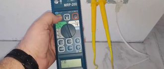
In the case of determining weather conditions, you will need a special wire that comes complete with the device, at the end of which there is a thermocouple, or something that measures the temperature. This can be seen in the photo. The wire is plugged into a special connector, the temperature measurement mode is selected and the value in degrees Celsius is shown on the screen.
Checking the cable insulation resistance with a megohmmeter
AID-70 device
Norms for children
Body temperature in young children is generally poorly controlled by the body and depends on many external factors, even ordinary overheating. For example, during sleep, a child's body temperature is higher than when he is awake. The result also depends on the method of measurement. The temperature in the mouth is considered normal for children if it does not exceed 37.1 degrees. At the same time, the measurement in the armpit will show the usual 36.6, but the measurement rate in the anus will be much higher and is usually half a degree higher than in the mouth. Since many parents measure their infants’ temperature rectally, you need to know about this.
There are also special nipple thermometers that are configured to immediately show the baby’s body temperature, as with axillary measurement.
How temperature is measured with a multimeter, how to check a temperature sensor with a tester
Multimeters are universal instruments for measuring various indicators of electrical equipment. Most often they are used for work by electricians, but sometimes they are used to measure temperature. This is possible if the device has the appropriate functions, or if it is possible to attach a microcircuit to it.
Basic moments
A multimeter is used as a thermometer if it is necessary to measure temperature in difficult conditions - an open flame, toxic substances, difficult access to an object, an object that is too hot.
Many multimeters have a built-in temperature measurement function. In this case, using the device is not difficult, since you do not have to make any changes to its design, you just need to figure out which mode to choose. Usually this mode is marked with the letters “temp”, and the multimeter comes with a thermocouple, which is a wire with a sensor. There are two sockets on the housing to connect a thermocouple.
Most testers are capable of working with temperatures ranging from -40 to 1000 degrees Celsius. If you have purchased an inexpensive multimeter, you should pay attention to which thermocouple is included. The fact is that most multimeters have fairly thin wires that can melt when exposed to temperatures above 250 °C. It is also necessary to pay attention to whether it is possible to measure the temperature of liquids or only gases.
If you are going to work with high temperatures, then it is better to replace the standard thermocouple with a special one, the design of which is designed for measurements in more difficult conditions.
For some devices, you will need to use a special adapter, since multimeters have single inputs, and a professional thermocouple has a miniature plug. After connecting the thermocouple, you must select the temperature measurement mode: it can be in degrees Celsius or Fahrenheit.
In order to find out what the temperature is, you need to touch the tip of the thermocouple to the object of interest. The data will immediately appear on the electronic display.
The duration of contact with the object is only 2-3 seconds; for accurate measurements, the contact must be tight. You can check if your multimeter is working correctly by comparing its readings with those of a thermometer. It is also important to monitor the polarity of the thermocouple connection.
No special mode
Is it possible to measure temperature with a multimeter that does not have a special mode for this? It turns out that this can really be done, but the device will need to be slightly upgraded. You need to purchase an LM-35 microcircuit, with its help the temperature readings will be converted into voltage, and the device will be able to recognize the data, but will indicate them in Volts. For example, 0.30 Volts will need to be understood as 30 degrees Celsius.
The use of a microcircuit does not require complex intervention in the design of the device and allows you to use any multimeter to measure temperature. In order for the chip to work, you will need:
- three wires that can be connected to the 10-ohm output of the device;
- a separate power source of at least 4 Volts, that is, 2 flat batteries.
If you need to measure not only positive, but also negative temperatures, you will also need to connect a reference voltage source.
The microcircuit itself is easy to connect. It has three connectors for positive and negative wires and an output sensor. This approach will allow you to transform any multimeter, making it more functional, while the design will be inexpensive.
Checking the temperature sensor with a tester
The question of how to check a temperature sensor with a tester is quite relevant for motorists. In order to carry out the necessary measurements, you can use any multimeter; in addition, you will need to remove the sensor itself and prepare a kettle of water. The sensor will need to be immersed in boiling water (the liquid temperature is always 100 °C). It is most convenient to secure the wires coming from the sensor with crocodile clips and connect them to the measuring device. After this, the multimeter must be set to current resistance measurement mode.
If the resistance readings of the sensor when exposed to a temperature of 100° do not exceed 210 Ohms, then the sensor can be safely changed, since its readings are incorrect. With such sensor resistance, you will encounter the fact that your car will boil regularly. By using a multimeter, you will eliminate the need to disassemble the cylinder head and carry out complex repairs, quickly identifying the cause of the problem at home. You can also choose the sensor that will display the data correctly.
Which device to choose
In principle, it is possible to measure temperature with any multimeter, but there are several important nuances. Before purchasing, you need to pay attention not only to the price, but also to the quality. It will be much more convenient if the multimeter is initially designed to measure different temperature ranges and has a special mode for this. Then you won’t have to modify it using additional devices.
The higher the functionality of the device, the more convenient and useful it is to use. It is better to purchase a device from a trusted store, since quite a lot of products from even well-known companies are counterfeited, not to mention unscrupulous manufacturers offering low-quality products. It is better to overpay a little, but have a guarantee of the reliability of the purchased tester.
Standard functions of the devices include the ability to measure voltage, resistance, DC and AC current.
Most models will allow you to ring the chain. The price often depends on what kind of display the tester has. If this is a regular screen with numbers, the device will cost less than an analogue with a full color display and the ability to control it.
The choice of multimeters is quite wide. You can always choose the right device based on functionality, price and quality. The device will become indispensable in many situations; it will help check not only the condition of wiring, but also many parts of various electrical appliances.
How to measure temperature with a multimeter?
See also reviews and articles:
- How to measure the voltage in a household electrical network with a multimeter?
- What can you measure with a multimeter in a car?
- How to measure AC and DC voltage?
- How to measure amperes with a multimeter?
- How to measure resistance with a multimeter?
- How to measure current with a multimeter?
- How to measure battery current with a multimeter?
Measure the temperature with a multimeter
Some models of control instruments have special functions. For example, to determine the temperature of very hot objects. In order to test the t value, standard probes are not used, but a special thermocouple is included in the kit. It is necessary to check hot, chemical, poisonous objects very quickly, so the temperature sensor of the multimeter installed in the thermocouple processes the received information within 2-3 seconds.
For a high-quality research result, it is necessary to check that the thermocouple is well fixed in the measuring device and ensure tight contact with the test object. In the work of an electronics engineer, this function is rarely in demand. Therefore, a device capable of performing such measurements can be considered specialized. But even if you do not need this function, the advantage of this model is the operating temperature range, the range of which is much wider than that of many other devices.
SUITABLE PRODUCTS
- Digital multimeter Rebel RB-33D 0 reviews
Buy
304 UAH
Code 31089
in the shop
- Digital multimeter Rebel RB-33С 0 reviews
Buy
335 UAH
Code 31088
in the shop
- Digital multimeter Rebel RB-33B 0 reviews
Buy
283 UAH
Code 31087
in the shop
- Digital multimeter Rebel RB-30D 0 reviews
Buy
335 UAH
Code 31086
in the shop
- Digital multimeter Rebel RB-30C 0 reviews
Buy
391 UAH
Code 31085
in the shop
- Universal multimeter MASTECH MY65 1 review
Buy
1280 UAH
Code 100
in stock
- Universal multimeter MASTECH MS8264 0 reviews
Buy
1209 UAH
Code 98
to order
- Multimeter MASTECH MY63 0 reviews
Buy
771 UAH
Code 99
to order
- Universal multimeter MASTECH MS8261 0 reviews
Buy
1126 UAH
Code 97
to order
- Universal multimeter MASTECH MAS838 + thermocouple 0 reviews
Buy
513 UAH
Code 80
to order
Share on social networks
Comments on the article “How to measure temperature with a multimeter? "
- Leave your comment on the article...
Leave your comment
Error
How to measure electrical resistance.
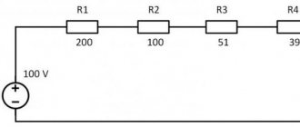
The red probe is connected to the middle connector of the multimeter, the black one to the bottom (COM). On the left side, below the DCV sector, there are five electrical resistance measurement limits:
1. 2000 k - from 0 to 2000 kiloohms (2 megoohms). 2. 200 k - from 0 to 200 kiloOhm. 3. 20 k - from 0 to 20 kiloohms. Using these limits, they measure the electrical resistance of constant resistors, adjust variables, and test the continuity of high-resistance windings of miniature relay solenoids.
4. 2000 Ohm (2koOhm) - from 0 to 2000 Ohm. This limit is ideal for testing the integrity of the coils of various relays, starters and electromagnets.
5. 200 Ohm - from 0 to 200 Ohm. The low resistance limit is suitable for testing electrical. incandescent light bulbs, electric windings. motors, electromagnetic couplings. As well as heating elements of household kettles, boilers, irons.
For example, we need to check the integrity of an incandescent light bulb. We set the mode switch to the limit of 200 Ohms - on the display we see the number 1 in the leftmost register, symbolizing an infinitely large resistance. At the same time, touch the upper part of the contact base with one probe, and its lower part with the other.
If the lamp is working properly, the multimeter will show a resistance from 1 to 100 Ohms - depending on its operating voltage and power. In particular, a 100 watt 220 volt incandescent lamp has a resistance of about 40 ohms when cold. If the lamp is faulty, the multimeter will not show any resistance.
How to measure temperature with a multimeter
A standard thermocouple consists of a sensor, a fireproof cable and a plug. The polarity is marked on the plug. We plug the plug into the socket of the multimeter, without confusing the plus and minus. We switch the selector to temperature measurement mode - it is simply labeled “K TYPE THERMOCOUPLE”.
Then everything is simple - we place the sensor in the environment whose temperature needs to be measured. Or press it to the surface. For pressing, you can use something with low heat capacity and thermal conductivity, but at the same time non-flammable.
Many people still do not know what kind of device a multimeter is, how to use it, and what it is needed for. To answer these questions, we will try to create detailed instructions.
A multimeter is a universal measuring device that includes several devices and is capable of measuring a number of electrical parameters, checking the serviceability of many radio components, and the integrity of the electrical circuit. It is convenient to have a compact device that can perform many measurements.
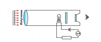
Measurement principles
Before you start studying a multimeter, you should familiarize yourself with the existing concepts and principles of using this device for the following types of measurements:
- Direct . They are carried out by directly connecting the probes of the device with the circuit being measured, or with a separate element, with instant display of information on the scale or digital display of the device. For example, when measuring current, the display shows this value in amperes; if voltage is measured, the result is shown in volts; and when measuring resistance, the value is shown in Ohms.
- Indirect . They are performed in several successive steps of different quantities, with further calculation of the dependent result. For example, you need to determine the power of a connected device in a DC circuit. To solve this problem, it is necessary to measure the voltage, then the current, then multiply the obtained measurement data. Thus, the inductance of the coil is determined using an alternating voltage generator. As the frequency of the current increases, the active resistance of the coil will increase, which means the current will decrease. Most often, indirect measurements require several instruments.
- Non-electrical quantities are measured using various converters in the form of sensors, amplifiers, shunts, etc. For example, many multimeters have the function of measuring light, temperature, and pressure. Using special electrodes, you can measure the moisture content of wooden boards, soil acidity, etc. These auxiliary transducers are usually purchased separately, but are sometimes included in the form of thermometers, lux meters or clamps for measuring the amount of current in the cable without contacting it.
This universal multimeter has become a good assistant for electricians and radio amateurs. Despite the presence of many modes, working with the device is quite simple.
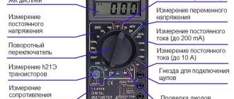
Design features
Most multimeters are similar to each other in the arrangement of indicators, control elements, and also in appearance. In the center there is usually a main switch in the form of a round disk with a convenient knob, which, when rotated, indicates which mode is currently on.
Inscriptions of ranges and mode names are located around the switch. Modes located next to each other are grouped and surrounded by a frame.
The multimeter is equipped with a liquid crystal screen, around which there may be auxiliary buttons for turning on the backlight and other additional options. Buttons can also be located on the sides of the case.
At the bottom of the front panel there are sockets for connecting measuring probes. The “ COM ” socket is a common negative terminal for connecting a black probe. The other two sockets are used to connect a red probe. One is for widespread parameter measurements and the other is for high current measurements.
Voltage measurement
To measure a parameter such as voltage with a multimeter, it is enough to use two groups of modes for direct and alternating current, which are designated DCV and ACV . To measure voltage in an alternating current network, there is no need to observe polarity, since alternating current does not have it.
The measurement range differs for different instrument versions. Most often, the measurement range for direct voltage is no more than 1000 V, for alternating voltage - up to 750 V. The entire range is divided into several measurement modes. If, for example, in the “up to 20 volt” mode you measure a higher value, the device will generate an error. And if you try to measure a value greater than the maximum permissible limit, for example, 2000 volts, the device will fail. Some models can withstand slightly exceeding the measurement limits, but it is hardly worth risking your money.
Maintaining the polarity of connecting the probes is necessary when measuring direct and pulsed current. This way you can determine the polarity of a source where you don’t know where the plus is and where the minus is. If the probes are connected in reverse, that is, the red probe is for minus and the black probe is for plus, then the display will show a “minus” sign in front of the numbers. Voltage is measured by connecting probes in parallel to the object being measured.
How to measure resistance
The most popular function in a multimeter is resistance measurement. Most often, the group of intervals for the ohmmeter is located at the bottom of the mode circle and is marked with the “Ω” symbol. There are several resistance measurement ranges.
If the resistor value is unknown, it is necessary to start measurements from a lower limit. The measurement accuracy of the device is low, and deviations can be up to 2%. The larger the interval of the measured value, the greater the deviation from the nominal value, especially for large resistances. If the battery in the device is discharged, the accuracy is significantly reduced. When measuring small resistances of a few ohms, the resistance of the probes and test leads should be taken into account. After touching the probes to the part being measured, you need to wait a few seconds for more accurate readings.
Current measurement
A multimeter can also be used to measure current. The socket for such measurements is limited to small values - usually from 0.2 to 0.5 amperes, depending on the design of the device. There is a separate socket for determining high current (up to 10 amperes), but in this case the permissible voltage is reduced by 50% of the highest measurement limit.
To measure the current, you need to put the switch in the appropriate position. Budget models usually only have the ability to measure DC current, unlike expensive models.
For direct and alternating current, the interval groups are different. If they are mixed up, nothing will happen to the device, the readings will simply be incorrect. If you exceed the maximum permissible values, the fuse may burn out or the electronic board may fail. In cheap models from China, two “positive” sockets may be connected together, which makes it impossible to measure large currents.
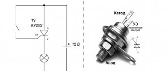
How to test diodes and check circuit integrity
For such measurements, there is a separate mode for diodes with its icon. To test it, you need to touch the terminals with the probes, then change the position of the probes with each other. In one of the options, there will be readings on the device screen, in the other there should be no reaction, since the diode conducts current only in one direction.
If a certain value is shown on the screen, then the black probe corresponds to the cathode of the diode, and the red probe corresponds to the anode. With such measurements, the multimeter can be considered a current source of 1 milliampere, and the value shown on the screen is the voltage drop in millivolts. Diodes can also be dialed in resistance mode. In this case, there will be readings in one direction, but not in the other. But it is better to check diodes in a mode specially designed for this, since this determines the voltage drop, which is used to judge the parameters of the diode if it is not marked.
Many models of such devices have the option of audible circuit testing. It turns on when the lowest resistance value is reached (about 100 Ohms). The sound signal may appear with some delay.
How does a multimeter measure temperature?
Many models of such devices are equipped with a special sensor for measuring temperature - a thermocouple. The maximum measured temperature can reach 800 degrees. The thermocouple is equipped with a double plug, which is inserted into the “ COM ” socket and another connector located nearby, or a separate pair of connectors marked “ C ”, depending on the version of the device.
The digital display shows the temperature in degrees Celsius. The multimeter may not have a special mode and connectors for measuring temperature. In this case, the temperature can be determined at the lowest limit of the DCV , using a graph of temperature versus EMF.
The accuracy of the measurements will be small, since when determining the temperature, it will not be the actual temperature that will be calculated, but the temperature difference between the device and the measured object. This error can be compensated for using a special function found in many measuring devices.
Checking bipolar and field-effect transistors
On the simplest and most budget models, you can check the pinout of transistors. A special mode is available for bipolar transistors ( hFE ), as well as a separate contact socket, which is divided into two parts, for transistors with PNP and NPN junctions. The contacts are marked with the letters E (emitter), C (collector) and B (base).
The contact sockets are arranged in such a way that a transistor whose pinout is unknown can be quickly rearranged and the pin positions changed. When the pinout is determined correctly, the transmission coefficient of the semiconductor will appear on the screen.
In the sockets, the contacts are recessed deeply, so it will not be possible to test transistors with short leads. Power transistors also cannot be checked with such a device, since the current generated by the multimeter will not be enough to open the semiconductor junction.
Field-effect transistors can be tested in diode mode if the pinout of the transistor is known in advance. First, the “ minus ” probe touches the drain, and the “ positive ” probe touches the source. This determines the integrity of the internal diode. If you connect the probes by exchanging them with each other, then there will be no voltage drop.
If you touch the “positive” probe of the gate, without removing the “negative” probe from the drain, the transistor should open, and the voltage drop will decrease and appear in two directions. The transistor will turn off if you touch the black probe to the gate without removing the red probe from the source.
Functions and buttons
An expensive multimeter may be equipped with an important “ HOLD ” button, which makes it possible to freeze the current position on the screen.
“Sophisticated” devices may have special buttons, by pressing which, the device will show only the minimum or maximum values. If you turn on any auxiliary measurement mode, the corresponding symbol will be displayed on the screen.
There are also multimeters with functions for testing capacitors, signal frequency, inductance, and oscilloscope functions.
Related topics:
Oscilloscope. Types and device. Operation and application. Peculiarities
Current clamps. Kinds. Job. Application. How to choose
Ammeter. Kinds. Job. Application. Peculiarities
Voltmeter. Kinds. Device. Job. Application. Peculiarities
Megaohmmeter. Kinds. Device. Job. Application. Peculiarities
principle of operation, how to check the device with a multimeter and how it works, what it is
The thermocouple for a gas boiler has a simple design, so it is quite easy to repair. A gas boiler is a complex structure that requires additional components. Particularly important in this device are the parts that control its operation and protect against overheating. One of the most important components of a gas boiler is a thermocouple. Let's figure out what it is and how to repair it yourself.
What is a thermocouple for a gas boiler
To understand how a thermocouple works, you must first determine what it is. Only in this case will you be able to change it in case of malfunction and check its operation.
The thermocouple is an element not only of a gas boiler, but also of a column. It is thanks to it that the safe operation of gas equipment is ensured.
You can find the answer to the question: “What is a thermocouple?” in special documentation. However, we offer you an explanation of the structure of this element in simple language.
What is a thermocouple:
- The thermocouple is a equipment monitoring device. It consists of two conductors of different types.
- The thermocouple conductors must be in contact with each other. Such contact is provided at one or two points of the device.
- Due to the different types of conductors in a thermocouple, when heated, they create a voltage between themselves. This voltage is taken into account during the operation of the gas boiler.
- It is thanks to the conductors and their characteristics that you do not have to use external excitation of the gas boiler. These parts can be powered autonomously.
Thus, the thermocouple is a temperature control sensor in the boiler. It has a very simple structure, which ensures its versatility.
The thermocouple for a gas boiler may differ in the length and thickness of the tube
There is only one rule regarding the choice of thermocouple. When purchasing such a device, you need to pay attention to the quality of fixation of the conductor connection points. If this parameter is not performed well, the device may produce an error of more than one degree. This is an unacceptable indicator for gas equipment.
How does a thermocouple work?
If you want to learn how to repair and troubleshoot a thermocouple, you must first understand the principle of its operation and understand how it works.
In fact, there is no great need to repair the thermocouple. This device has a very affordable price, which makes it possible to replace it frequently.
So, we have already figured out how a thermocouple works. It consists of two conductors connected at one or more points. This device looks like a thick metal wire with thickenings at the ends. The thickenings are conductors, and the wire itself consists of chromel and aluminum.
Thermocouple operating principle:
- Dissimilar metals connected to each other, or rather their junction, are heated to a certain temperature;
- Stress develops at the cold ends of these metals;
- A measuring device is connected to the ends of the conductors, and the circuit is closed;
- Due to the resulting voltage, induction occurs in the solenoid valve coil;
- Thanks to this, the shut-off valve opens and is held open.
If we explain how we see how a thermocouple works, then the principle of its operation will be as follows: we press the rod of the electromagnetic valve, opening it manually, the igniter receives a portion of gas, from which it flares up, at this time the ends of the thermocouple located above it heat up, through After half a minute, this element begins to generate voltage and the valve opens, you can release the rod.
Advantages of a thermocouple for a boiler
The thermocouple is present in all gas heating equipment. It is found in both columns and boilers. At the same time, previously this element was not used in boilers and they managed quite well without it. Why is it that now not a single gas boiler can do without this element?
The thermocouple itself is inexpensive, but the wires installed between the panel and the thermocouple are more expensive than other elements of the device.
The thermocouple gained its popularity due to the many advantages of its use. After all, only with the advent of this device, manufacturers were able to provide safe and high-quality electric ignition.
Advantages of using a thermocouple:
- Despite the fact that the thermocouple is a flame control sensor, it can also be a temperature tester;
- This element of a gas boiler is designed very simply, there are no additional parts or complex equipment, such a device makes the thermocouple cheap;
- This part can withstand a wide range of variable temperatures;
- The accuracy of the thermocouple is high, which is why it can be used in such dangerous products as gas boilers and water heaters;
- Repairing and installing a thermocouple is so simple that even an ordinary person can handle it.
Among the advantages of a thermocouple, it is worth noting its compactness and low cost. Despite the fact that a thermocouple has many advantages, it has its disadvantages.
Firstly, the relationship between heating temperature and potential growth is not linear, that is, the electric potential does not increase with increasing temperature. Secondly, the limit to potential growth is quite small. These negative qualities do not affect the operation of the equipment as a whole, but when temperatures change, the device requires high-quality calibration. Also, the advantage of a thermocouple - simplicity and reliability - is also its disadvantage. You ask how? The fact is that if the thermocouple burns out, and this sometimes happens, it will be impossible to repair it. In this case, the thermocouple will simply have to be replaced. In addition, a gas boiler will not work without this element. However, the price of the thermocouple is quite reasonable, and its installation is quite simple.
How to check a thermocouple on a gas boiler
Unfortunately, the thermocouple fails more often than other parts of a gas boiler. In this case, all equipment simply stops working. Therefore, when a gas boiler fails, the first suspicion arises that it is the thermocouple that has burned out.
If your gas boiler fails, the first thing you need to do is check the thermocouple. It is this element that most often causes the entire equipment to stop working.
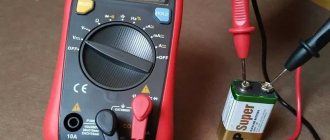
Before you go to the store for a new thermocouple, you need to check whether this is really the cause of the equipment breakdown. You can do this without calling a specialist yourself. However, as you work, you will have to take measurements with a multimeter, so make sure you have one in advance. You can buy it in a store, or call your friends and find it for free.
Checking the thermocouple for serviceability:
- Disconnect the end of the thermocouple from the solenoid valve. To do this they need to be untwisted.
- Remove the thermocouple from the boiler. Heat its end, which was located above the boiler burner, over a candle or gas burner;
- Next, you need to wait half a minute and measure the readings at the input contact using a multimeter. If they are less than 17 millivolts, then there is a malfunction in the thermocouple.
In this simple way, you can check whether the thermocouple is the cause of the gas boiler stopping. This work is simple and does not require much time. The only problem in this case is finding a multimeter.
Thermocouple repair or replacement
In most cases, repairing a failed thermocouple is impossible. The fact is that if this device burns out, then there is nothing to repair there, so we propose to consider the process of replacing it.
In most cases, any thermocouple is suitable for a wide variety of boilers. It's all about the prostate, its structure and versatility.
Replacing the thermocouple is a fairly simple job. Even a person far from such work can cope with it. Therefore, in this case, you can do without the help of a specialist.
If you do not have experience repairing thermocouples, then you should contact a professional
Steps for thermocouple stone:
- The thermocouple is installed on the gas line through a special pipe, to which the thermocouple is attached using a copper nut. To disconnect the thermocouple, you simply unscrew this nut.
- You also need to unscrew the compression screw. You will find it under the bracket.
- Now you can remove the old thermocouple.
- To install a new element, you need to tighten the nut and screw. In this case, it is necessary to check that the connection is tight. If this is not the case, then use ceramic or polymer gaskets.
As you can see, replacing a thermocouple is a very simple job. The main thing is that your actions do not damage other parts of the boiler, for example, the separator.
Connecting the thermocouple to the microcontroller
| Thermocouples are widely used where it is necessary to accurately measure high temperatures, temperatures up to 2500°C. That is, where digital sensors would immediately die from overheating, thermocouples are used. There are quite a few types of thermocouples, but the most widely used are chromel-alumel (type K) thermocouples, due to their low cost and almost linear change in thermopower. This type of thermocouples are installed in water heaters and other household appliances with temperature control; they are widely used to control the temperature when melting metal; with the help of these thermocouples, the heating of the tip in the soldering station is controlled. Therefore, it will be very useful to get to know them better. A thermocouple is two conductors made of different metals and having a common point of contact (junction). At the point of this contact a potential difference arises. This potential difference is called thermopower and directly depends on the temperature at which the junction is located. Metals are selected in such a way that the dependence of thermopower on heating temperature is most linear. This simplifies temperature calculations and reduces measurement errors. Thus, widely used chromel-alumel thermocouples have a fairly high linearity and stability of readings over the entire range of measured temperatures. Below is a graph for chromel-alumel thermocouples (type K) showing the dependence of the resulting thermopower on the junction temperature (at the end of the article there will be a link to a graph with higher resolution): Thus, it is enough to multiply the thermopower value by the required coefficient and obtain the temperature without bothering with tabular values and approximation - one coefficient for the entire measurement range. Very simple and clear. But the question arises about connecting the thermocouple to the microcontroller. It is clear that if there is voltage at the thermocouple output, then we will use the ADC, but the potential difference at the thermocouple output is too small to detect anything. Therefore, first it needs to be increased, for example, by using an operational amplifier. Let's take a standard non-inverting operational amplifier circuit: The ratio of input and output voltages is described by a simple formula: Vout/Vin = 1 + (R2/R1) The signal gain depends on the values of feedback resistors R1 and R2. The amount of signal amplification must be selected taking into account what will be used as the reference voltage. Let's say the microcontroller supply voltage is 5V as a reference. Now we need to decide on the temperature range that we are going to measure. I took the measurement limit to be 1000 °C. At this temperature value, the thermocouple output will have a potential of approximately 41.3 mV. This value should correspond to a voltage of 5 volts at the ADC input. Therefore, the op-amp must have a gain of at least 120. As a result, the following circuit was born: In my stash I found a long-assembled board with this opamp, assembled as a preamplifier for a microphone, so I used it: I assembled the following diagram for connecting a two-line display to a microcontroller on a blogboard: The thermocouple also lay idle for a long time - it came with my multimeter. The junction is closed in a metal sleeve. Bascom-AVR code for working with thermocouple: $regfile = "m8def.dat" I’ll briefly tell you how this happened for me. The standard for measuring temperature was steam in a boiling kettle. For the purity of the experiment, I first measured the temperature of the steam with a multimeter, connecting a thermocouple to it. Having made sure that the readings were correct, I measured the temperature with the newly made device and, adjusting the division coefficient, set the value to 100°C. After setting the first control point, it would be good to repeat the above at another known temperature, but I did not experiment further. In the flame of a lighter I measured ~700 °C (which seems to be true), but at room temperature the device output was 50 °C, probably due to the garbage in the low-order bits of the ADC. But I’m thinking of assembling, for example, a thermostat for a soldering iron that will do just fine. PCB with thermocouple amplifier Graph of thermopower versus temperature Useful document with characteristics of different types of thermocouples | |
| Category: How to connect | Added: 03/26/2012 | |
| Views: 111356 | Comments: 15 | Tags: LCD, ADC, thermocouple | Rating: 4.2 / 18 |
| Total comments: 15 | |
| +1 Spam 13 I already wrote that the op-amp has a bias voltage. So, there are also displacement currents, they are insignificant, but when measuring such small voltages as with a thermocouple, they play the role of uncompensated errors. In general, in order to somehow compensate for them, the inputs of the op-amp are loaded with resistors. To a first approximation, we can assume that the bias currents are the same for the inverting and non-inverting inputs. Accordingly, the resistors at the inputs must be the same. At the inverting input, in our case, a resistor of 1 kOhm and 5.1 + 120 kOhm is connected in parallel, so the equivalent resistance at this input is 1 kOhm, therefore, strictly speaking, at the non-inverting input there should be a resistor R4 not 10 kOhm, but 1 kOhm Well, and, of course, the resistor plays some protective role. Analog technology, especially the measurement of small currents and voltages, requires a very careful and competent approach. |
| 0 Spam 12 what function does resistor R4 perform? |
| 0 Spam 11 forter , thank you for the clarification! |
| +1 Spam 10 Hello. Colleagues! Regarding why R2 is needed? Circuit R2C1 is simply a low-pass filter. As you know, op-amps have their own noise, and finally, interference can also reach its input. It is in order to get rid of or at least weaken these effects that such chains are used. But, in my opinion, it would be more correct to use a resistor with a nominal value of, say, 100 KOhm, and increase the capacitance of the capacitor to 0.1 μF. True, you cannot reduce the resistance too much - self-excitation of the op-amp may occur. There is also a remark - by changing the gain, we simply change the resulting slope of the dependence of the voltage at the output of the op-amp on temperature, without taking into account that the op-amp has another very unpleasant effect - zero offset. This means that even if there is no signal at the output (we can think of it as the input), there is always a constant offset. If you take another op-amp that has zero balancing terminals (for example, like the domestic 140UD6), you can get rid of this - a multi-turn resistor is connected between the balancing terminals, and its motor is connected to the power supply, but this is only for bipolar power supply. All op amps suffer from this effect. Everything would be fine, but, being balanced at one temperature, the op-amp will become unbalanced if its temperature changes - this is the so-called zero temperature drift. If anyone has worked with electron beam oscilloscopes, they know that a few minutes after turning it on, the beam necessarily moves up or down. This effect is zero drift. For this reason, precision op-amps are used, especially when measuring very low voltages (as in the case of a thermocouple), in which this effect is much smaller, but they are much more expensive than ordinary op-amps |
| 0 Spam 9 Read more about cold junction compensation. Here it is shown what it is for https://www.compeljournal.ru/enews/2007/15/10 |
| 0 Spam 8 The op-amp still gives a very small output current, tens of microamps for memory. And the op-amp output has very low resistance. And therefore, if R2 is reduced, there will be no difference, IMHO. in general, I put this summary in accordance with the diagram on the radio cat about a digital soldering iron, there is a similar amplifier circuit and it costs exactly 1 MOhm, I decided to go according to the proven scheme) |
| 0 Spam 7 I HAVE A QUESTION, WHY DO YOU NEED A 1 MΩ RESISTOR R2? IF THE DATASHEETS ON THE ADC SPECIFY THAT: The ADC is optimized for analog signals with an output impedance of approximately 10 kΩ or less. AS I UNDERSTAND, THE OUTPUT RESISTANCE SHOULD BE LESS THAN 10KH, BUT YOU HAVE ALREADY 1M? |
| 0 Spam 6 You're right, search rules) It's clearly and simply written here |
| 0 Spam 5 they are needed in crafts... tell us…. |
| 0 Spam 4 thank you very much for the article. but I have one request... since everyone comes to you for information... then tell us in the next material in your intelligible form about these operational amplifiers. It’s clear that books and search rule…. but we eat with you and there are a lot of subtleties that are too much for us... |
| 0 Spam 3 Thanks for the advice, an interesting link is not considered spam) There is a 5 kOhm trimmer on my handkerchief, maybe they can adjust the gain of the op-amp, but in general, yes, this is a tedious task. Each thermocouple must be individually calibrated. Even with a large difference between the hot and cold junctions (metal connection points and free ends), an error of tens of degrees may occur, therefore, to accurately measure high temperatures, it is necessary to fence the cold junction compensation circuit. And most importantly, a ten-bit ADC microcontroller is clearly not enough to measure the temperature range above 1000 degrees. |
| 0 Spam 2 By the way, I forgot to say that there is a connection error in the circuit at R6? r8. there shouldn't be. |
| 0 Spam 1 at room temperature the device output was at 50°C. Most likely, your op-amp gain was not selected correctly, when I was making an IR soldering station I spent a lot of time setting up thermocouple amplifiers, the point was as follows, this circuit was taken as a basis https:// ur5kby.at.ua/publ….-1-0-67 (sorry for the link in advance, do not consider it spam) at the beginning, the resistor according to circuit R6 with the temperature coupler immersed in melt water was set to 0°C, then in series with the resistor R9 one more tuning resistor was introduced, and the value of R9 was reduced, and with this resistor, changing the gain, we achieved readings of 100 ° C in boiling water, only after all this the amplifier began to linearly amplify over the entire temperature range and not lie. |
Add comments can only registered users. [Registration | Entrance ]