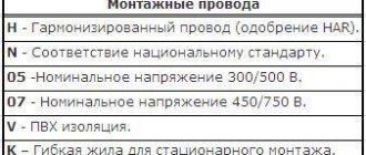
Fastening wires to pin insulators of intermediate supports
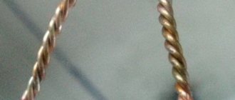
Fastening the wire to the neck of the insulator. On intermediate single-post supports, the methods of fastening the wires depend on the location of their fastening on the pin insulator: side tying on the neck (Fig. 1) or on the head (head tying - Fig. 2).
Rice. 1. Technology of “simple” side knitting of wires: a - without winding on the wire; b - with winding on the wire Fig. 2. Technology for performing head binding of wires on a pin insulator Note. Rice. 2 is shown for comparison with the side knitting of the wire. For basic information about head knitting, see below. Head knitting is used for fastening wires of large cross-sections, side knitting for small cross-sections. The question of where the wire is attached to the neck of the insulator of intermediate supports is not provided for by the standards; the wire can be attached both from the inside and outside in relation to the support body. However, it is considered advisable to fasten the wire on the outside of the insulator in relation to the support body in order to remove the wire from the support body as far as possible, reducing the likelihood of the insulator being blocked by birds landing on the wire. But fastening the wire from the inside of the pin insulator, i.e. closer to the body of the support, ensures the safety of people and animals, since if the wire binding breaks or the clamp malfunctions, the wire falls on the hook or traverse of the support. This is especially well ensured on wooden supports, because the wire in this case is isolated from the ground (when the support is dry, not wetted by rain) and the wire does not burn out from the flow of single-phase ground fault currents through the support, for example, on a 6-35 kV overhead line, and does not fall to the ground, where it is especially dangerous for others. On angular intermediate supports, when the wire is not broken at the support, the wire is placed on the outside of the pin insulator in relation to the angle of rotation of the line. The material for knitting aluminum and steel-aluminum wires and wires made of aluminum alloys are aluminum wires (preferably two wires from wire A 95), and for steel wires - soft steel wire with a diameter of at least 2 mm. About 60 cm of wire is consumed per knitting. In critical cases, in order to avoid damage to the aluminum wires, the binding site should be wrapped with aluminum tape with a cross-section of 10×1 mm, as shown in Fig. 1 Before knitting, the ends of the wires of the required length are prepared in advance in accordance with the knitting method. When lateral knitting (Fig. 1), the middle of a piece of knitting wire is placed on the neck of the insulator. One end of the wire is wrapped around the wire from bottom to top, and the other - from top to bottom. Both ends are brought forward, twisted again into a cross around the insulator and the wire, and then wound on both sides around the wire with at least six to eight turns on each side of the insulator. When securing the wire, do not allow it to bend under the influence of the binding tension. The wire and binding must not be damaged by pliers. Knitting of aluminum and steel-aluminum wires should be done by hand without using pliers or pliers.
Diameter of binding wire, mm
Rewind length, mm
Total length of knitting, mm
Fig.3. Side knitting of type VSh-1 of wire on a pin insulator. When lateral knitting of wires, wire knitting of type VSh-1 (Fig. 3) and type SSh-1 and SSh-2 (Fig. 4) is used. The sequence of operations when attaching a wire to the neck of an insulator using VSh-1 type wire is as follows:
- The wire is lifted from the mounting roller or from the hook onto the neck of the insulator and, at the point where it touches the insulator, winding is carried out in both directions, but not wider than the diameter of the neck of the insulator.
- A knitted wire with a length of at least 1400 mm is divided in half, starting from point “O”, the neck of the insulator is covered with wire and on both sides of the insulator, 3 (at least) turns are made on the wire on both sides of the insulator.
- Both remaining ends of the binding wire are thrown around the neck of the insulator to the opposite side to the line wire.
- At least 10 turns are made to each of the remaining ends on the line wire, as shown in Fig. 3, and then the ends of the knitted wire are pressed against the wire manually (without pliers). The left end of the knitting wire is attached similarly along the lines “in” and “in/”.
3.3. Fastening wires on intermediate supports with pin insulators
3.3.1. To secure the protected wire to the insulators (having an upper groove) of the intermediate supports, as a rule, spring spiral ties with a polymer coating are used. The binding is applied over the protective sheath of the wire.
3.3.2. For reinforced fastening, a set of two spiral bindings is used. The wire is located in the insulator groove. The spiral should begin to be wound as close as possible to the insulator; each spiral is wound onto the wire on the opposite side of the insulator.
3.3.3. For intermediate fastening, either a single polymer-coated spring steel spiral tie or a plastic tie can be used.
3.3.4. When using pin insulators with a groove on a 6 - 20 kV overhead line (for example, type SDI 37 made in Finland), the wire laid in the groove is fastened with a set of two spiral ties. The first spiral covers the insulator and wire on one side, the second - the insulator and wire on the opposite side. This ensures enhanced fastening.
3.3.5. A diagram of the intermediate fastening of the wire to the neck of the insulator is shown in Fig. 26 [], using one spiral knitting.
3.3.6. Reinforced fastening of the wire to the neck of the insulator is ensured by applying a second spiral so that its turns occupy the free space between the turns of the first spiral.
3.3.7. Intermediate fastening of the protected wire to the head of the pin insulator is carried out using one spiral according to the diagram in Fig. 27 []; For this purpose, a spiral is used, shown in Fig. 28 [].
How to properly knit a wire with an insulator
8.12.1 Adjusted wires are secured to the insulators of intermediate, corner or terminal supports with ties that should not allow the wire to move from one span to another. Knitting is done with a dressing wire, the length of which is indicated in Table 8.13.
8.12.2 On straight sections of the line, tying is performed with two pieces of dressing wire in the following order (Figure 8.36):
a) cover the neck of the insulator with a piece of dressing wire so that one end of the wire is longer than the other by an amount equal to the diameter of the insulator head;
b) both ends of the dressing wire are twisted so that they fit closely to the groove in the insulator head;
c) with a second piece of binding wire, cover the neck of the insulator on the other side and also twist the ends of the wire to the groove in the head of the insulator;
d) the long ends of both pieces of binding wire are thrown respectively to the other side of the insulator through the wire located in the groove and bent down; then they, together with the short ends, are tightly wound onto the linear wire using special pliers (which have indentations in the jaws). In the absence of such pliers, bimetallic or copper wires are knitted with pliers with copper inserts without notches.
Figure 8.36 — Tying of wires on insulators of intermediate supports
8.12.3 On corner supports, the wires are secured with one piece of wire. In this case, a piece of dressing wire, the length of which is determined according to Table 8.13, is applied crosswise to the linear wire. The ends of the dressing wire are wrapped around the neck of the insulators, and then, using pliers, tightly wrapped around the line wire (Figure 8.37).
Figure 8.37 Attaching the wire to the insulator on the corner support
The wires are fastened to the terminal supports as shown in Figure 8.38.
Figure 8.38 — Fastening the steel wire to the terminal support
Table 8.13 - Selecting the diameter and length of the dressing wire
| Diameter of linear wire, mm | Insulator type | Diameter of dressing wire, mm | Length of dressing wire, cm | |
| on straight sections | on corner supports | |||
| 1 | 2 | 3 | 4 | 5 |
| 5i4 4 4 3 3 2.5 2.0 1.5 | TF-20 TF-20 TF-16 TF-12 TF-12 TF-12 TF-12 TF-12 | 2,5 2,5 2,5 2,0 2,0 1,2 1,2 1,0 | 51 50 46 45 40 35 34 30 | 56 55 51 50 45 40 39 35 |
8.12.4 Non-ferrous metal wires are secured to the terminal support using copper or aluminum tubes as shown in Figure 8.39.
If there are no tubes, the termination is done as shown in Figure 8.40.
| Figure 8.39 — Termination of non-ferrous metal wire | Figure 8.40 — Termination of small diameter wire by twisting |
8.12.5 Steel-aluminum wires are secured to insulators with soft aluminum wire with a diameter of 3 mm or galvanized steel dressing wire with a diameter of 2.5 mm. At the point of knitting, aluminum tape is tightly wound onto the wire in the direction of the aluminum conductors.
When tying bimetallic steel-copper wires with a bimetallic dressing wire, copper tape (foil) measuring 300x10x0.1 mm is placed under the latter. If copper dressing wire is used, copper tape is not placed.
8.12.6 When fastening (tying) wires to insulators, it is recommended to use cage.
Source
Methods of knitting power lines
8.12.1 Adjusted wires are secured to the insulators of intermediate, corner or terminal supports with ties that should not allow the wire to move from one span to another. Knitting is done with a dressing wire, the length of which is indicated in Table 8.13.
8.12.2 On straight sections of the line, tying is performed with two pieces of dressing wire in the following order (Figure 8.36):
a) cover the neck of the insulator with a piece of dressing wire so that one end of the wire is longer than the other by an amount equal to the diameter of the insulator head;
Fastening the wire to the neck of the insulator.
On intermediate single-post supports, the methods of fastening the wires depend on the location of their fastening on the pin insulator : side knitting on the neck
(Fig. 1) or on the head (
head binding
- Fig. 2).
Rice. 1. Technology of “simple” side knitting of wires: a - without winding on the wire; b - with winding on the wire Fig. 2. Technology for performing head binding of wires on a pin insulator Note. Rice. 2 is shown for comparison with the side knitting of the wire. For basic information about head knitting, see below. Head knitting is used for fastening wires of large cross-sections, side knitting for small cross-sections. The question of where the wire is attached to the neck of the insulator of intermediate supports is not provided for by the standards; the wire can be attached both from the inside and outside in relation to the support body. However, it is considered advisable to fasten the wire on the outside of the insulator in relation to the support body in order to remove the wire from the support body to the greatest possible distance, reducing the likelihood of the insulator being blocked by birds landing on the wire. But fastening the wire from the inside of the pin insulator, i.e. closer to the body of the support, ensures the safety of people and animals, since if the wire binding breaks or the clamp malfunctions, the wire falls on the hook or traverse of the support. This is especially well ensured on wooden supports, because the wire in this case is isolated from the ground (when the support is dry, not wetted by rain) and the wire does not burn out from the flow of single-phase ground fault currents through the support, for example, on a 6-35 kV overhead line, and does not fall to the ground, where it is especially dangerous for others. On angular intermediate supports, when the wire is not broken at the support, the wire is placed on the outside of the pin insulator in relation to the angle of rotation of the line. The material for knitting aluminum and steel-aluminum wires and wires made of aluminum alloys are aluminum wires (preferably two wires from wire A 95), and for steel wires - soft steel wire with a diameter of at least 2 mm. About 60 cm of wire is consumed per knitting. In critical cases, in order to avoid damage to the aluminum wires, the binding site should be wrapped with aluminum tape with a cross-section of 10×1 mm, as shown in Fig. 1 Before knitting, the ends of the wires of the required length are prepared in advance in accordance with the knitting method. When lateral knitting (Fig. 1), the middle of a piece of knitting wire is placed on the neck of the insulator. One end of the wire is wrapped around the wire from bottom to top, and the other - from top to bottom. Both ends are brought forward, twisted again into a cross around the insulator and the wire, and then wound on both sides around the wire with at least six to eight turns on each side of the insulator. When securing the wire, do not allow it to bend under the influence of the binding tension. The wire and binding must not be damaged by pliers. Knitting of aluminum and steel-aluminum wires should be done by hand without using pliers or pliers.
| Mounting type | Diameter of binding wire, mm | Rewind length, mm | Knitting length, mm | Total length of knitting, mm |
| VSH-1 | 2,8. ..3,8 |
Fig.3. Side knitting of type VSh-1 of wire on a pin insulator. When lateral knitting of wires, wire knitting of type VSh-1 (Fig. 3) and type SSh-1 and SSh-2 (Fig. 4) is used. The sequence of operations when attaching a wire to the neck of an insulator using VSh-1 type wire is as follows:
1. The wire is lifted from the mounting roller or from the hook onto the neck of the insulator and, at the point where it touches the insulator, winding is carried out in both directions, but not wider than the diameter of the neck of the insulator.
2. A knitted wire with a length of at least 1400 mm is divided in half, starting from point “O”, the neck of the insulator is covered with wire and on both sides of the insulator, 3 (at least) turns are made on the wire on both sides of the insulator.
3. Both remaining ends of the binding wire are thrown around the neck of the insulator to the opposite side to the line wire.
4. At least 10 turns are made to each of the remaining ends on the line wire, as shown in Fig. 3, and then the ends of the knitted wire are pressed against the wire manually (without pliers). The left end of the knitting wire is attached similarly along the lines “in” and “in/”.
A rational way of lateral fastening is fastening using a bolt clamp (Fig. 5). For lateral fastening of the wire on the neck of the head of the pin insulator, a design developed in the Latvenergo system is also used (Fig. 6). This fastening is a half-clamp with a shaped profile with a groove and two covers that are pushed onto the bent ends of the half-clamp and hold the mounted wire. The principle of operation of such fastening is as follows. that the bending arrow H of the half-clamp is smaller than the diameter D of the neck of the insulator, due to which a force P arises, pressing the wire against the insulator P = Рт -2sincc, () where Рт is the tension along the wire, and the angle a is formed as a result of bending the wire with the half-clamp. Fig.5. Lateral fastening of the wire to the pin insulator of the intermediate support using a bolt clamp
| Mounting type | Insulator type | R, mm | 1„ mm | mm | mm | h, mm | Ream length, mm |
| SSH-1 | ShF10-G | ||||||
| SSH-2 | ShF20-V |
Fig.4. Lateral fastening of the wire on the neck of the pin insulator using binding type SSh-1 and SSh-2: a - assembled view; b - sketch of the bracket
Fig.6. Lateral fastening of the wire to the pin insulator using a half-clamp with covers: a - half-clamp; b - cover
To protect intermediate supports from breakage when the wire is pulled on one side (when the wires break in the intermediate span), clamps of the ZAK-10 type are used to fasten the wires (Fig. 7). The clamp has a design that, when pulled on one side, weakens the adhesion force between the clamp and the insulator.
| Clamp brand | Brand and wire cross-section | Clamp application area | Design load on clamping elements, kN | Clamp weight, kg | |
| A | AC | AN | AJ | icy area | wind region |
| ZAK 10 | — | 25/4,2 | |||
| 35/6,2 | I+IV | I+V | 0,70 | 0,2 | |
| 50/8,0 |
Rice. 7. Fastening the 6-10 kV overhead line wire using a ZAK-10 clamp: 1 - ZAK-10 type clamp; 2 — hook grip; 3 - insulator; 4 - overhead line wire; P - design load on the clamping elements Note. The additional double fastening wire must be taut. Rice. 8. Double fastening of the wire on a pin insulator: a - on hooks; b - on the traverse of the intermediate support. 1 - insulator; 2 — PA or PAB clamp Head wiring. Rice. 9. Fastening the wire to the head of the pin insulator using a viscous type VG-1. Fastening the wire to the head of a pin insulator can be done using a viscous type VG-1 (Fig. 9). The sequence of operations for this type of knitting: a loop is placed on the neck of the insulator and secured by twisting so that one end is longer; the long end is secured to the wire, and the wire is secured with two loops. Anti-vibration head binding of the wire on a pin insulator, which protects the wire from destruction when vibration occurs, is shown in Fig. 10. The strength of wire sealing with wire knitting is assumed to be no more than 150 kg. You should not create blind fastenings on intermediate supports with knitted wire, since this, due to the operating conditions of the support, turns it into an anchor one, which can lead to an accident if the wires break. The head tying on the pin insulator of the intermediate support is performed with two ends of the tying wire (Fig. 2). Both ends are twisted around the head so that the ends of the tie are on both sides of the insulator groove. The ends of the knitting are made of different lengths. The two short ends are wrapped 4...5 times around the wire, and the long ends are placed over the insulator head and also wound around the wire 4...5 turns.
Application of standard ties for non-insulated wires of 6-35 kV overhead lines
| Mounting type | Brand and wire cross-section | Clamp application area | Terrain | Insulator type | ||
| Icy area | wind region | dance district | ||||
| VSH-1 | ApS 35/6.2 AS 50/8 AS 70/11 | I-VII | IV | With rare and moderate | Populated and unpopulated | ShF10-G ShF20-V |
| SSH-1 | ApS 35/6.2 AS 35/8 AS 70/11 AS 95/16 | I-VII and special | I—V | With rare, moderate and frequent dancing | Populated and unpopulated | ShF10-G |
| SSH-2 | ShF20-V | |||||
| VG-1 | ShF10-G ShF20-V |
Figure 10. Anti-vibration wire binding on the head of the pin insulator
The damper wiring of the wires is shown in Fig.
11. Spiral ties type BC for fastening insulated and non-insulated wires to pin insulators
Spiral ties (TU-3449-054-27560230-2010) are intended for intermediate fastening of insulated SIP-3 wires to pin insulators of overhead power line supports; SAX and bare wires grade A; AC; AF with a cross section of up to 150 mm2.
Knittings are made for single, double fastening and for fastening wires of different diameters on two insulators. A single fastening contains one side brace installed on the insulator. Double fastening includes two tension ties installed on one insulator. Fastening on two insulators includes two side ties. The slipping strength of a wire secured with one or two side ties is 2-3 kN. The sealing strength of a wire secured with two tension ties is 4-5 kN.
The specified strength of the seal ensures the safety of intermediate supports in the event of a wire break and other emergency situations.
Spiral knitting markings:
B.C.
- dmin/dmax-D-AB or BC-dpr-D-AB;
BC
- spiral knitting;
dmin/dmax or dpr
- minimum and maximum or nominal wire diameters;
D
is the diameter of the insulator neck;
A
- type of fastening to the insulator:
1
- one side tie;
2
– two tension ties;
3
– for fastening on two insulators paired with viscous type 1;
B
— wire type:
1
– for insulated wire;
2
– for bare wire.
An example of a knitting designation for fastening insulated wires: BC-14/16-72-11 – spiral knitting for fastening an insulated wire with a minimum diameter of 14 mm and a maximum diameter of 16 mm. on an insulator with a neck diameter of 72 mm with one side knit. An example of a tying designation for fastening bare wires: BC-12.3-46-22 – spiral tying for fastening a bare wire with a diameter of 12.3 mm on an insulator with a neck diameter of 46 mm using two tension ties.
Attention! From 01.12.2010 the marking of matings has been changed.
Rice. 1. Side knitting for single wire fastening on pin insulators. Side knitting (Fig. 1) consists of a strand assembled from three spirals glued together.
In the middle part the knitting has a twisted loop, with the help of which it is attached to the neck of the insulator. The right branch (when the knitting is positioned according to the figure) when leaving the loop is located above the left branch. An abrasive is applied to the inside of the strand.
Rice. 2. Fastening the AC 95/16 wire using a single strand BC-13.5/14.0-85-12 on a pin insulator.
The tension tie (Fig. 3) is made in the form of a U-shaped loop, the middle part of which has a twisted section with which the tie covers the neck of the insulator.
Rice. 3. Tension knitting for double fastening of the wire.
On the loop part of any binding there is a color mark in the middle corresponding to the brand of insulator on which the binding is mounted (see Table 1).
On one of the branches, closer to the edge, there are marks corresponding to the brand of wire on which the bundle is mounted (see Table 2). The marks are read in the direction from the center of the binding to the edge of the branch.
Knitting is used only with the wire diameter and insulator brand indicated in the marking.
When securing wires and cables (ropes), the following requirements are met [2]: aluminum, steel-aluminum wires and aluminum alloy wires when installed in steel support and tension (bolt, wedge) clamps must be protected by aluminum, copper wires - by copper gaskets; fastening of wires on pin insulators must be made with wire ties, special clamps or clamps, and the wire must be laid on the neck of the pin insulator (Fig. 13.41 and 13.42); wire binding must be made with wire made of the same metal as the wire. When knitting, bending the wire with the knitting wire is not allowed; branch wires from overhead lines with voltage up to 1 kV must be anchored; in each span of overhead lines with voltages above 1 kV, no more than one connection is allowed for each wire or rope; When tying wires to insulators with wire, make sure not to damage the wires (as well as the binding wire) with pliers. Mounting on the neck (rather than on the head) of the pin insulator is more reliable and durable in operation, and is less damaged by vibration and dancing of wires. In Fig. 13.43 shows the recommended side knitting of aluminum and steel-aluminum wires for 6-10 kV overhead lines. In this case, the wires are protected from abrasion against the insulator by winding them with wire.
Rice. 13 41. Fastening wires on pin insulators of overhead lines with voltage up to 1 kV, a—clamp for the wire, b—installation of the clamp on the neck of the insulator; c - fastening the wire, side view, d - the same top view, g - lever for mounting the clamp, f - fastening the wire to the neck of the insulator with wire ties, g - the same using a bracket, 1 - clamp, 2 - clamp tongue, 3 - insulator, 4 - wire; 5 - wooden handle, 6 - pipe, put on the handle and secured with a screw; 7 - wire binding, 8 - bracket
Rice. 13 42. Fastening wires on pin insulators of overhead lines with voltages above 1 kV a - clamp for fastening wires of 10 kV overhead lines, b - single tie on the neck of an overhead line insulator up to 35 kV; c - the same double knitting, 1 - grip, 2 - bracket, 3 - insulator, 4 - overhead line wire, 5 - knitting wire, 6 - steel pin. Wire knitting starts from point O (Fig. 13.43.6), coinciding with the middle knitting wire. The right end of the wire follows the line and is secured with three turns on the wire, then follows line a and is secured to the left side of the wire. Likewise, the left end follows the line b and bv. Fig. 13 43 Lateral binding of wires to pin insulators of 6-10 kV overhead lines: a - general view of the wiring, 6 - wiring diagram, i - tight winding, 2 - three turns; 3 - ten turns In Fig. 13.44 shows anchor and corner fastening of wires on pin insulators. In garlands of hanging insulators, the wires are secured in clamps. The wires are secured to the anchor supports using tension garlands with tension clamps. Whenever possible, install the wire without cutting it, installing both tension garlands at the same time. In this case, the tension clamps are placed at a distance equal to the length of the loop, which is determined according to the project. Wedge clamps are mounted in the following order: remove the wedge and pin; Having made sure that all parts of the clamp are in good condition, insert the wire into the clamp body so that the mouth of the clamp is opposite the mark on the wire indicating the location of the clamp installation; insert a wedge and hit the copper or aluminum lining with a hammer, which protects the end of the wedge from damage, secure the wire in the clamp; At the same time, make sure that the clamp does not move along the wire. After this, the clamp is attached to the ear of the insulator garland and the pin, washer and cotter pin of the clamp are inserted into place. On intermediate supports, the wires are secured in supporting clamps.
Rice. 13 44 Anchor and corner fastening of wires on pin insulators: a - single anchor suspension; b—anchor double suspension; c - corner double reinforced suspension; 1 - tie clamps On supports that limit the span of the intersection, the following are used: for suspended insulators - blind clamps, for pin insulators - double parallel fastening (Fig. 13.44.6). To protect the outer layer of aluminum and steel-aluminum wires, especially in sliding-type clamps, the wire is wrapped with aluminum tape 1 mm thick or with aluminum wire taken from scraps of the wire being mounted. With pin insulators, wires and cables are transferred from unrolling rollers to the neck of the insulator; with suspended insulators, they are transferred to the corresponding clamp. The transfer of the wire from the unrolling roller, suspended from a garland of insulators, into the clamp is carried out from a telescopic tower, while the wire is temporarily pulled to the support with a cable or rope through a block. The cables are secured to the supports using clamps.
Site search:

![Turboloan [CPS] RU March](https://dush-pol.ru/wp-content/uploads/turbozajm-cps-ru-mart-330x140.jpg)